Transcription
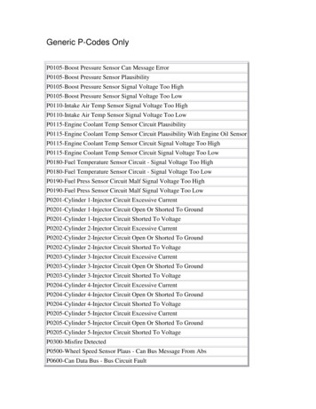
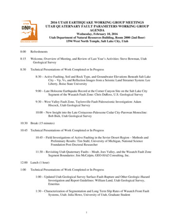
SHORT CIRCUIT FAULT CALCULATIONSShort circuit fault calculations as required to be performed on all electrical service entrances by NationalElectrical Code 110-9, 110-10. These calculations are made to assure that the service equipment will clear afault in case of short circuit.To perform the fault calculations the following information must be obtained:1. Available Power Company Short circuit KVA at transformer primary : Contact Power Company, mayalso be given in terms of R jX.2. Length of service drop from transformer to building, Type and size of conductor, ie., 250 MCM,aluminum.3. Impedance of transformer, KVA size.A.B.C.D.%R Percent Resistance%X Percent Reactance%Z Percent ImpedanceKVA Kilovoltamp size of transformer. ( Obtain for each transformer if in Bank of 2 or 3)4. If service entrance consists of several different sizes of conductors, each must be adjusted by (Ohmsfor 1 conductor)(Number of conductors)This must be done for R and XThree Phase SystemsWye Systems: 120/208V277/480V3 , 4 wire3 4 wire120/240V 3 , 4 wireDelta Systems:240V3 , 3 wire480 V3 , 3 wireSingle Phase Systems:Voltage 120/240V 1 , 3 wire. Separate line to line and line to neutral calculations must be done for singlephase systems. Voltage in equations (KV) is the secondary transformer voltage, line to line.Base KVA is 10,000 in all examples.Only those components actually in the system have to be included, each component must have an X and an Rvalue. Neutral size is assumed to be the same size as the phase conductors.See page 14 & 27 for example in Buss Book.6/14/02Chapter 10: Short Circuit Fault Calculations1/10
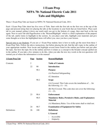
Short Circuit CalculationsOnly one calculation needs to be done for most 3 phase systems. This is for the per unit method.3 PhaseI SCA KVA Base 3 KVLL total PUZKVA Base 10,000Single PhaseTwo separate calculations must be done for single phase systems.I SCA KVA Base( KV line to line ) (total PUZ)I SCA KVA Base(KV line to neutral) ( total PUZ)KVA Base 10,000KVLLKVLL.230KV.115KVSee page 12 Buss Book for transformer and wire equations.6/14/02Chapter 10: Short Circuit Fault Calculations2/10
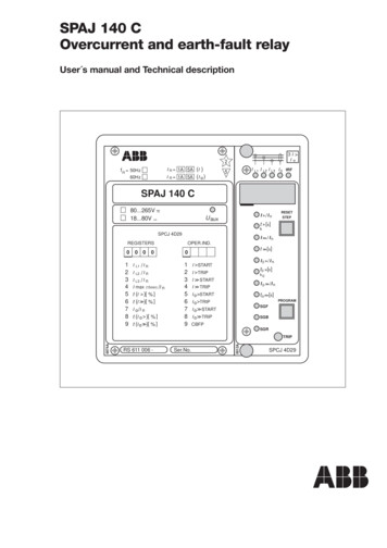
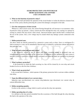
Table 1- Transformer Impedance DataPercent R, X and Z based on Transformer KVANote 1: These values are for three phase, liquidfilled, self-cooled transformers.Note 2: Due to the trend toward lower impedancetransformers for better voltage regulation, the actualtransformer impedances may deviate from theNEMA Standard given at left. Therefore, for actualvalues, obtain nameplate impedance from owner ormanufacturer. The percent X and percent R valuesare desirable for calculation.6/14/02Chapter 10: Short Circuit Fault Calculations3/10
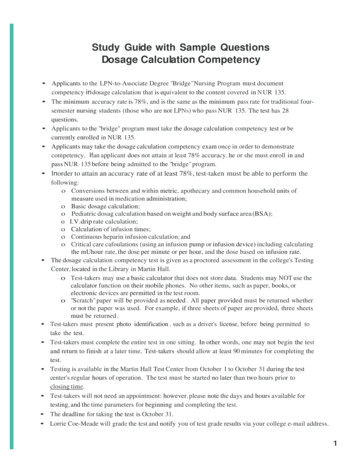
6/14/02Chapter 10: Short Circuit Fault Calculations4/10
Appendix6/14/02Chapter 10: Short Circuit Fault Calculations5/10
Appendix6/14/02Chapter 10: Short Circuit Fault Calculations6/10
Appendix6/14/02Chapter 10: Short Circuit Fault Calculations7/10
Appendix6/14/02Chapter 10: Short Circuit Fault Calculations8/10
Appendix6/14/02Chapter 10: Short Circuit Fault Calculations9/10
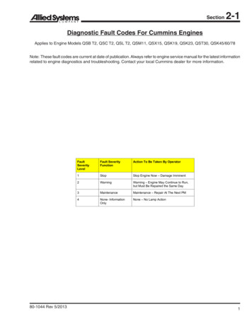
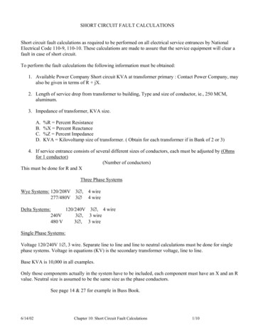
Circuit Breaker Data6/14/02Chapter 10: Short Circuit Fault Calculations10/10
See page 14 & 27 for example in Buss Book. 6/14/02 Chapter 10: Short Circuit Fault Calculations 1/10 . Short Circuit Calculations Only one calculation needs to be done for most 3 phase systems. This is for the per unit method. 3 Phase I SCA KVA Base 3 KVLL total PUZ