Transcription
CCNPRouting andSwitchingTSHOOT 300-135Quick ReferenceBrent StewartCisco Press800 East 96th StreetIndianapolis, Indiana 46240 USA
[ ii ]CCNP Routing and Switching TSHOOT 300-135 Quick ReferenceCCNP Routing and Switching TSHOOT 300-135Quick ReferenceBrent StewartCopyright 2015 Pearson Education, Inc.Published by:Cisco Press800 East 96th StreetIndianapolis, IN 46240 USAAll rights reserved. No part of this book may be reproduced ortransmitted in any form or by any means, electronic or mechanical, including photocopying, recording, or by any informationstorage and retrieval system, without written permission fromthe publisher, except for the inclusion of brief quotations in areview.Printed in the United States of AmericaFirst Printing November 2014ISBN-13: 978-0-13-392948-5ISBN-10: 0-13-392948-5Warning and DisclaimerThis book is designed to provide information about networking.Every effort has been made to make this book as complete andas accurate as possible, but no warranty or fitness is implied.The information is provided on an “as is” basis. The authors,Cisco Press, and Cisco Systems, Inc. shall have neither liabilitynor responsibility to any person or entity with respect to anyloss or damages arising from the information contained in thisbook or from the use of the discs or programs that may accompany it.The opinions expressed in this book belong to the author andare not necessarily those of Cisco Systems, Inc.PublisherPaul BogerAssociate PublisherDave DusthimerBusiness OperationManager, CiscoPressJan CornelssenExecutive EditorBrett BartowManaging EditorSandra SchroederDevelopment EditorMarianne BartowSenior ProjectEditorTonya SimpsonCopy EditorPaula LowellTechnical EditorSean WilkinsEditorial AssistantVanessa EvansCover DesignerMark ShirarCompositionStudio GalouIndexerBrad HerrimanProofreaderMegan Wade-TaxterTrademark AcknowledgmentsAll terms mentioned in this book that are known to be trademarks or service marks havebeen appropriately capitalized. Cisco Press or Cisco Systems, Inc., cannot attest to theaccuracy of this information. Use of a term in this book should not be regarded as affectingthe validity of any trademark or service mark.
[ iii ]Special SalesFor information about buying this title in bulk quantities, or for special salesopportunities (which may include electronic versions; custom cover designs;and content particular to your business, training goals, marketing focus, orbranding interests), please contact our corporate sales department atcorpsales@pearsoned.com or (800) 382-3419.For government sales inquiries, please contact governmentsales@pearsoned.com.For questions about sales outside the U.S., please contactinternational@pearsoned.com.Feedback InformationAt Cisco Press, our goal is to create in-depth technical books of the highest qualityand value. Each book is crafted with care and precision, undergoing rigorousdevelopment that involves the unique expertise of members from the professionaltechnical community.Readers’ feedback is a natural continuation of this process. If you have anycomments regarding how we could improve the quality of this book, orotherwise alter it to better suit your needs, you can contact us through emailat feedback@ciscopress.com. Please make sure to include the book title andISBN in your message.We greatly appreciate your assistance.
[ iv ]CCNP Routing and Switching TSHOOT 300-135 Quick ReferenceAbout the AuthorBrent Stewart, CCNP, CCDP, CCSI, MCSE, is the vice president of ManagedServices at Stalwart Systems (stalwartsystems.com), an innovative IT engineeringfirm focused on secure IT architectures. His experience includes designing andmanaging a large-scale worldwide voice, video, and data network. He was a coursedirector for Global Knowledge and participated in the development of BSCI withCisco and has written and taught extensively on CCNA and CCNP. Brent livesin Hickory, North Carolina, with his beautiful wife, Karen, and their mischievouschildren Benjamin, Kaitlyn, Madelyn, and William.About the Technical ReviewerSean Wilkins is an accomplished networking consultant for SR-W Consultingand has been in the field of IT since the mid-1990s, working with companies suchas Cisco, Lucent, Verizon, and AT&T, as well as several other private companies.Sean currently holds certifications with Cisco (CCNP/CCDP), Microsoft (MCSE),and CompTIA (A and Network ). He also has a Master of Science in informationtechnology with a focus in network architecture and design, a Master of Sciencein organizational management, a Master’s Certificate in network security, aBachelor of Science in computer networking, and Associates of Applied Science incomputer information systems. In addition to working as a consultant, Sean spendsmost of his time as a technical writer and editor for various companies; check outhis work at his author website: www.infodispersion.com.
Contents at a GlanceContents at a GlanceHow This Book Is OrganizedixChapter 1Tools and Methodologies of TroubleshootingChapter 2Troubleshooting Switching TechnologiesChapter 3Troubleshooting IP NetworkingChapter 4Troubleshooting Routing Technologies2842551[v]
[ vi ]CCNP Routing and Switching TSHOOT 300-135 Quick ReferenceContentsHow This Book Is Organized ixChapter 1Tools and Methodologies of Troubleshooting 1Troubleshooting Methodology 1Structured Troubleshooting 2What to Do When Nothing Works! 4Best Practices for Routine Maintenance 5Methodology6Common Tasks6Troubleshooting ToolsConfigurations912Other Tools 16Working with External ToolsPacket SniffingNetFlow171718SNMP and EEM 19Hardware Diagnostics 19Discovery 22Self-Documenting NetworksChapter 226Troubleshooting Switching TechnologiesHardware 29Troubleshooting ScenarioVLANs3232DHCP Troubleshooting Example33Spanning Tree Protocol 34BPDU Guard ExampleSVIs3838Troubleshoot SVIs38Trunking and EtherChannel 39Port Security 40Chapter 3Troubleshooting IP Networking 42IP Address Assignment 4228
ContentsNTP, Syslog, and SNMPNTP4445Syslog46SNMP46Gateway Redundancy 47Filtering 49NAT51Steps to Troubleshooting NAT51Rule Out NAT 52Understand the Objective of NAT 52Verify the Translation53Verify the Translation Is Being Used53Authentication 54Chapter 4Troubleshooting Routing TechnologiesNetwork Layer Connectivity 55Routing Protocols56Router Performance 56EIGRP 59Is the Correct Route Advertised? 59Is the Correct Route Communicated? 60Is There a More Desirable Path? 61OSPF61Is the Correct Route Advertised? 62Is the Correct Route Communicated? 62Is There a More Desirable Path? 63BGP63Is the Correct Route Advertised? 63Is the Correct Route Communicated? 63Is There a More Desirable Path? 64Route Redistribution 6555[ vii ]
[ viii ]CCNP Routing and Switching TSHOOT 300-135 Quick ReferenceCommand Syntax ConventionsThe conventions used to present command syntax in this book are the sameconventions used in the IOS Command Reference. The Command Referencedescribes these conventions as follows: Boldface indicates commands and keywords that are entered literally asshown. In actual configuration examples and output (not general commandsyntax), boldface indicates commands that are manually input by the user(such as a show command). Italic indicates arguments for which you supply actual values. Vertical bars ( ) separate alternative, mutually exclusive elements. Square brackets ([ ]) indicate an optional element. Braces ({ }) indicate a required choice. Braces within brackets ([{ }]) indicate a required choice within an optionalelement.
How This Book Is Organized[ ix ]How This Book Is Organized Chapter 1, “Tools and Methodologies of Troubleshooting”: This chapterfocuses on minimizing time-to-repair. It examines the techniques that canbe applied to decrease downtime. The scientific method is suggested as amodel for troubleshooting. Descriptions of tasks commonly used to maintainperformance and prepare for problems, such as documentation and scheduledpreventative maintenance, are provided. Finally, it covers IOS tools, suchas archiving, logging, and configuration rollback, that are valuable in thetroubleshooting process. Chapter 2, “Troubleshooting Switching Technologies”: Ethernet isubiquitous in campus networks and data centers. More and more servicesare traveling on Ethernet, such as storage, virtualization, and telephony. Thischapter describes troubleshooting the critical pieces: Spanning Tree, VLANs,InterVLAN routing, and gateway redundancy. Chapter 3, “Troubleshooting IP Networking”: This chapter describesissues around IP services and starts with a discussion of IP addressing. Italso discusses services such as NTP, syslog, and SNMP. Chapter 4, “Troubleshooting Routing Technologies”: This chapter coverstroubleshooting link layer connectivity, OSPF, EIGRP, and BGP routingprotocols and router performance.
This page intentionally left blank
CHAPTER 3Troubleshooting IPNetworkingIP Address AssignmentThis section describes issues regarding IP services and starts with a discussion about IP addressing. Even when Layer 2 connectivity is intact, failuresat Layer 3 prevent communication.IP addresses identify interfaces, not devices. The principal IP parameters areaddress, subnet mask, and (except on routers) default gateway. Addressesare unique, but a mask and gateway should be common on a subnet. Addressinformation can be either statically assigned or obtained from Dynamic HostConfiguration Protocol (DHCP).When troubleshooting IP connectivity, refer to the following steps:Step 1.Use traceroute to test connectivity or (if broken) the last pointworking in the path.Step 2.If the problem is in the local subnet, ensure that the IP addressis unique. Non-unique addresses create a log message that lookslike “1w2d: %IP-4-DUPADDR: Duplicate address 10.1.1.1 onFastEthernet0/1, sourced by 0002.1234.5678.” Also ensure thatthe subnet mask is the same as the one on the gateway, and thatthe gateway IP is correct. Many organizations use the first usableaddress in the subnet for the default gateway to prevent suchconfusion.Step 3.If the problem is between the local subnet and the endpoint,verify whether routes exist on the intermediate devices. It is easyto forget to troubleshoot the return path, but make sure you checkthis as well. If the far end doesn’t know how to route back, thesymptoms will be identical to an outbound routing problem.Step 4.Check intermediate devices for logic that would interfere withrouting, such as policy-based routing, access lists, and networkaddress translation. If possible, remove these elements for testing.
Chapter 3: Troubleshooting IP Networking[ 43 ]Addresses can also be assigned through DHCP. DHCP is sometimes used fornetwork devices, particularly on commodity connections to service providers. More commonly, DHCP is used on end systems, and troubleshootingfrom a network perspective involves understanding how DHCP is supportedby the router.DHCP passes configuration information, including IP configuration, uponrequest. A client sends a broadcast DHCPDiscover to ask for informationand the server responds with DHCPOffer. Because more than one DHCPserver could respond, the client responds to the offer it is accepting withDHCPRequest. Most clients accept the first offer received. Routers caneither act as DHCP servers or as relays, which forward the broadcasts toremote servers.A simple DHCP configuration is shown in Example 3-1. It supplies DHCPaddresses in the range 10.1.1.0/24 and runs on the interface attached to thatsubnet. Verify the current assigned addresses using show ip dhcp bindingor show ip dhcp pool. You can also see the action of DHCP by using debugip dhcp server packet event.Example 3-1 DHCPIp dchp pool tshootNetwork 10.1.1.0 255.255.255.0Default-router 10.1.1.1Dns-server 10.1.1.3Supporting a remote DHCP server requires forwarding broadcastDHCPDiscover messages to a remote server. For instance, a branch coreswitch might forward DHCP requests back to a central resource using thehelper address, as shown in the following configuration:Interface vlan100Ip helper-address 10.1.1.1Start-up problems are issues where network connectivity starts slowly andis not in place until after the DHCP process times out. A perfect exampleis when spanning-tree startup places a port in blocking. Start-up issues canbe recognized because rerunning DHCP works after the port is active (onWindows, this can be tested using winipcfg/renew). Spanning-tree startupcan be fixed by applying PortFast.TSHOOTDHCP events can create a disproportionate amount of drama because of theimpact on users. The principal way to recognize a DHCP problem is thatPCs have addresses that start 169.254. These are auto-assigned addressesused when no DHCP server is found. DHCP problems break into three largegroups.
[ 44 ]CCNP Routing and Switching TSHOOT 300-135 Quick ReferenceConnectivity failures to the server also prevent DHCP from completing asexpected. In this second type of problem, PCs also auto-assign an addressbut will not be fixable by renewing later. Troubleshoot this by following thepath back to the DHCP server and verifying whether DHCP traffic can flow.DHCP servers can fail, and a best practice is to run multiple DHCP serverswithin an enterprise. A failed server is also verified (and worked around) bytemporarily placing a DHCP server on the local router.The third group of DHCP problems is the ignorant or malicious introductionof an unauthorized DHCP server in the network. Surprise! If a consumerdevice is brought in, such as a wireless access point, it can be recognizedby 192.168.1.0/24 addresses being assigned. When a rogue DHCP serveris introduced maliciously, detecting it can be difficult. An attacker coulddo this to assign legitimate addresses with a traffic capture device listed asthe gateway. When recognized, the ARP table can be used to track back theswitch port of the bogus gateway.DHCP snooping is a technique to deal with spurious DHCP offers. Anadministrator identifies a port that has an authorized DHCP server (thisworks best if the DHCP server is the only device attached through that port).DHCP snooping then drops DHCPOffers coming from untrusted ports. Italso drops release messages coming from ports other than the port wherea user was assigned a given address. Violations also get logged, such as%DHCP SNOOPING-5-DHCP SNOOPING UNTRUSTED PORT.Configure DHCP snooping globally and identify a trusted interface as shownin the following configuration. View DHCP snooping information by usingshow ip dhcp snooping.DSW1(config)# ip dhcp snoopingDSW1(config)# interface f1/1DSW1(config-if)# ip dhcp snooping trustTSHOOTNTP, Syslog, and SNMPNTP, Syslog, and SNMP are services that aid in troubleshooting. Eachneeds to be set up beforehand so that data can be used in the troubleshooting process. Network Time Protocol (NTP) helps establish causality—whichevent came first—when comparing logs from different devices. Syslogallows log collection in a central location. Simple Network ManagementProtocol (SNMP) collects network telemetry in a central location. SNMP cangather data points, such as capacity utilization, processor and memory usage,and error rate. From the SNMP collector, these data points can be graphed toshow sudden changes or to analyze trends and suggest proactive next steps.
Chapter 3: Troubleshooting IP Networking[ 45 ]NTPExample 3-2 is a standard NTP setup. NTP starts by identifying a time zone.NTP draws time from a time server on the Internet—clock1.unc.edu in thisexample—and acts as a time server (master) for the network. Two importantpieces to this configuration are to protect time records from changes meantto obfuscate an attack (time communication is encrypted to prevent maliciouschanges to time records) and to communicate time to known devices only.Example 3-2 NTP Configurationclock timezone EST -5clock summer-time CDT recurringclock calendar-validntp update-calendarntpntpntpntpmaster 2!stratum 2authenticateauthentication-key 11 md5 tshoottrusted-key permit clock1.unc.edudeny anypermit R2deny anyntp access-group peer 2ntp access-group serve-only 1ntp server clock1.unc.eduntp peer R2Verify NTP using show ntp associations. In Example 3-3, a public NTPserver is specified and synched. If a server does not sync, it is almost alwaysbecause of a communication issue. Troubleshoot by verifying whether theserver is reachable with ping and that NTP traffic is not blocked by a firewall or access list.R1# show ntp associationsaddressref clockstwhenpollreachdelayoffsetdisp* 152.2.21.1152.2.21.112910243774.2-8.591.6* master (synced), # master (unsynced), selected, - candidate, configuredTSHOOTExample 3-3 NTP Associations
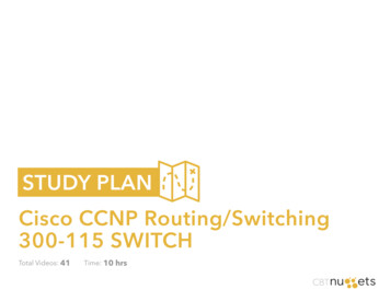
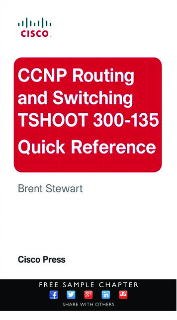
[ 46 ]CCNP Routing and Switching TSHOOT 300-135 Quick ReferenceSyslogLogging errors to the system is enabled by default, but it must be enabled toship the logs to a remote destination. The logging level must be specified aswell. Figure 3-1 illustrates levels 0 through 7. Logging at least at level 3 andmaking sure that the time on the device is accurate are good practices.Figure 3-1Logging Levels7. Debugging6. Information5. Notifications4. Warnings3. Errors2. Critical1. Alerts0. EmergenciesLogging issues are generally related to routing; however, the local devicekeeps a copy of its logs in memory and can be referenced if logs are notflowing to the central server. A generic configuration for logging is shown inthe following configuration:TSHOOTService timestamps log datetimeLogging trap 3SNMPMost of TSHOOT concerns active break/fix situations, but the most commonproblems are usually the slowly developing, insidious type. A good exampleis when capacity utilization creeps up. By the time the default network monitoring system (users) recognize there is an issue, it is too late! Ordering and
Chapter 3: Troubleshooting IP Networking[ 47 ]receiving new service takes months, during which time service will be unsatisfactory. Enterprises of any size should have some system to gather SNMPtelemetry and analyze it regularly. A number of commercial and open-sourcepackages are quite good.SNMP is also a way for an attacker to control a network, so it must be usedcautiously, kept updated, and secured. A sample SNMP configuration isshown in Example 3-4.Example 3-4 SNMP Access ListSnmp-server community tsh0ot ROSnmp-server community S3cret RW 10Snmp-enable trapsSnmp-server host 10.1.1.3Ip access-list 10 permit host 10.1.1.3Two communities are defined—one is read-only and one allows administrative changes. The read/write string is limited to the defined host.Gateway RedundancyHosts are configured with a default gateway—a router address that passestraffic off the local subnet. The problem is that router failures strand thehosts. The solution is first-hop redundancy protocols, which enable tworouters to cooperatively support a single IP, which is then given to hosts as adefault gateway.The three first-hop redundancy protocols are as follow:Hot Standby Router Protocol (HSRP) is an older Cisco proprietaryprotocol. One router is the active and one is the standby. The routerspass keepalives that enable the standby to recognize failure of theprimary router. Virtual Router Redundancy Protocol (VRRP) is an open standard butis otherwise similar to HSRP. Because HSRP works, many organizations have continued to use it. Gateway Load Balancing Protocol (GLBP) is an open standard, but itenables simultaneous load balancing over as many as four gateways.Because HSRP is the most common, this section focuses on HSRP. Thegeneral configuration and troubleshooting strategy applies as well to VRRPand GLBP, however.TSHOOT
[ 48 ]CCNP Routing and Switching TSHOOT 300-135 Quick ReferenceHSRP is configured under the interface using standby commands. Routers inthe same HSRP group share a MAC address and IP address, so standby isused to identify the group and virtual IP.By default, each HSRP speaker has a priority of 100. The speaker with thehighest priority is the active router. If a new router starts, however, HSRPdoes not change the active router until the failure of the active router.To change this so that the higher priority is instantly recognized, use thepreempt command. Example 3-5 shows an HSRP snippet to illustrate theconfiguration.Example 3-5 Example HSRPInterface f0/0Ip address 10.1.1.2 255.255.255.0Standby 2 ip 10.1.1.1Standby 2 priority 120Standby 2 preemptVerify the HSRP state of a router using show standby, which summarizesthis information to a table as shown in Example 3-6. To see detailed information on HSRP, such as timers and virtual MAC, use show standby (asshown in this example).Example 3-6 HSRPTSHOOTR1# show standbyGigabitEthernet0/1 - Group 135State is Active23 state changes, last state change 25w6dVirtual IP address is 135.159.64.1Active virtual MAC address is 0000.0c07.ac87Local virtual MAC address is 0000.0c07.ac87 (v1 default)Hello time 5 sec, hold time 20 secNext hello sent in 0.284 secsPreemption enabledActive router is localStandby router is unknownPriority 150 (configured 150)Group name is "hsrp-Gi0/1-135" (default)Richardson-rtr01# show standby interface gi0/1GlobalConfg: 0000Gi0/1 If hwBCM1125 Internal MAC (27), State 0x210040Gi0/1 If hwConfg: 0000Gi0/1 If hwFlags: 0000Gi0/1 If swConfg: 0000
Chapter 3: Troubleshooting IP NetworkingGi0/1 If swGi0/1 Grp 135Gi0/1 Grp 135[ 49 ]Flags: 0000Confg: 0072, IP PRI, PRIORITY, PREEMPT, TIMERSFlags: 0000HSRP virtual IP Hash Table (global)103 172.25.96.1Gi0/1Grp 135HSRP MAC Address Table43 Gi0/1 0000.0c07.ac87Gi0/1 Grp 135Just as show standby brief provides an HSRP overview, show vrrp briefand show glbp brief describe the VRRP and GLBP environments, respectively. Similarly, show standby interface and debug standby have equivalents for the other first-hop redundancy protocols.A simple configuration for HSRP might look like the following:Interface f0/0Ip address 10.1.1.2 255.255.255.0Standby 43 ip 10.1.1.1Troubleshoot first-hop redundancy protocols by using the following steps:Make sure that the “real” address of the routers is unique. Tworouters in a standby group each have a different permanentaddress. In the previous simple configuration, the interface isaddressed as 10.1.1.2/24.Step 2.Check that the standby IP and group numbers match. In the previous configuration, the interface is in HSRP group 43 and theshared IP is 10.1.1.1.Step 3.Verify that the standby IP address is in the local subnet. If theshared address isn’t in the local subnet, local devices won’t beable to reach it! In the earlier configuration, 10.1.1.1 is in the10.1.1.0/24 subnet.Step 4.Verify whether access lists are not filtering standby traffic.Access lists must permit keepalive traffic between the participating routers and allow clients to use both routers as a gateway.FilteringAccess lists (ACL) are a tool to block traffic as it crosses a router. StandardIP access lists filter traffic based on source address. Extended access listsTSHOOTStep 1.
[ 50 ]CCNP Routing and Switching TSHOOT 300-135 Quick Referencefilter traffic based on source and destination IP address, as well as transportlayer details.NoteFilter traffic based on destination address using a route to null0. To filter traffic going to192.168.21.0/24, enter a static route: ip route 192.168.21.0 255.255.255.0 null0.Standard IP access lists are numbered 1–99 or named. Extended accesslists are numbered 100–199 or named. Using named access lists is stronglyencouraged because this aids in understanding the intent of the ACL later.Access lists are applied to interfaces in a direction (in or out, relative to thedevice), and access lists always end with an implicit deny.A simple standard access list might be used on the perimeter to block bogussource addresses (known as bogons) as illustrated in Example 3-7. Assumingthat fastethernet1/1 is the outside interface, the access list needs to be appliedinbound (traffic coming into the router from outside would have sourceaddresses that should be blocked).Example 3-7 Bogon ListTSHOOTInterface fastethernet1/1Ip access-group bogon list inIp access-list standard bogon listDeny 0.0.0.0 0.255.255.255Deny 10.0.0.0 0.255.255.255Deny 127.0.0.0 0.255.255.255Deny 169.254.0.0 0.0.255.255Deny 172.16.0.0 0.15.255.255Deny 192.168.0.0 0.0.255.255Deny 224.0.0.0 31.255.255.255Permit anyA slightly more complicated configuration might be used to limit accessfrom a “guest” network as shown in Example 3-8. The idea here is thatguests are allowed to attach through fastethernet1/2 (perhaps this is attachedto a wireless access point). Guests should be allowed DNS and web access,but nothing else. Note that the access list allows tcp/80 and udp/53—everything else is denied implicitly.Example 3-8 Guest ACLInterface fastethernet1/2Ip access-group guest access inIp access-list extended guest access
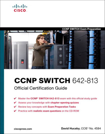
Chapter 3: Troubleshooting IP Networking[ 51 ]Permit tcp any any eq 80Permit udp any any eq 53Focus on four principal areas for access list troubleshooting:1. Is this an ACL problem? If possible, remove the access list and test.2. Check the applied interface and direction. The temptation is to reviewthe access list first, but verifying direction is important so that sourcesand destinations are correctly interpreted. It is also possible that theapplied interface is not on the path the traffic is taking!3. Check the access list entries. Are addresses and port numbers enteredcorrectly?4. Review the order of operations. Remember that ACLs are processedtop-down and the first match (permit or deny) is executed. Could thetraffic be matching an earlier statement? Check this by moving the linein question to the top of the list temporarily.NATNetwork Address Translation (NAT) is the process of translating sourceor destination IP addresses as traffic traverses a router. Router interfacesare described as outside (the public side) or inside (the private side).Translations are described from points of view—local describes the addressseen by an inside observer and global describes what a public observer sees,as shown in Figure 3-2.Figure 3-2NAT TermsLocalGlobalInsideOutsideSteps to Troubleshooting NATConsider the following steps to troubleshooting NAT. Each step is exploredfurther in the sections that follow.TSHOOTNAT can map addresses to pool or to a single address. Mapping all theinside connections to a single public address is an example of Port AddressTranslation (PAT) or overloading.
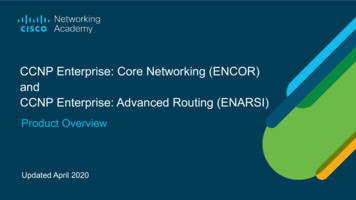
[ 52 ]CCNP Routing and Switching TSHOOT 300-135 Quick ReferenceStep 1.Attempt to rule out NAT. Check connectivity.Step 2.Understand the objective of NAT.Step 3.Verify the translation.Step 4.Verify whether the translation is being used.Rule Out NATFrom the translating router, source a ping from the outside interface asshown in Figure 3-3. This verifies that traffic flows bidirectionally from therouter and that neighbors have a return route. If ping doesn’t work, checkthe connectivity from the router. If all lines appear stable, then investigaterouting, especially the return path.Figure 3-3Simple NAT192.168.1.1192.168.1.310.1.1.110.1.1.2As shown in Figure 3-3, use an extended ping or traceroute to originatetraffic from the 10.1.1.1 interface to check connectivity. If possible, examineneighboring devices to determine whether their routing tables include thereturn route to 10.1.1.0/24.Understand the Objective of NATReview what the NAT configuration is trying to accomplish, and verify thatall elements of the configuration appear correct. A generic configurationfor NAT identifies inside and outside interfaces and an ip nat commandas shown in Example 3-9. A common error is to either not identify or tomisidentify interfaces.TSHOOTExample 3-9Simple NAT 1:1 ConfigurationInterface f0/0Ip add 10.1.1.1 255.255.255.0Ip nat outsideInterface f0/1Ip address 192.168.1.2 255.255.255.0Ip nat insideIp nat inside source static 192.168.1.3 10.1.1.2
Chapter 3: Troubleshooting IP Networking[ 53 ]In Example 3-9, which builds on Figure 3-3, the router is being asked totranslate traffic from the user to a single outside address. Note that the insideand outside are correctly identified and that the ip nat statement has theaddresses in the correct order.Verify the TranslationMake sure that the translation is entered into the translation table on therouter correctly. This is accomplished by using show ip nat translation. Weare translating the inside address, so the following configuration tells us thatthe inside address, as seen from the Internet, is 10.1.1.2. The inside address,as seen from the private network, is 192.168.1.3.R2# show ip nat translationPro Inside globalInside local--- 10.1.1.2192.168.1.3Outside local---Outside global---Verify the Translation Is Being UsedHaving checked the configuration and the translation table, the last step is toensure that the traffic is actually being translated. This is accomplished byusing debug ip nat. Example 3-10 shows the debug output. Here, the PC ispinging an outside address to create traffic.Example 3-10 debug NATR2# debug ip natR2# show logSyslog logging: enabled (0 messages dropped, 0 flushes, 0 overruns)Console logging: level debugging, 39 messages loggedMonitor logging: level debugging, 0 messages loggedBuffer logging: level debugging, 39 messages loggedTrap logging: level informational, 33 message lines loggedLog Buffer (4096 bytes):Some less common errors can occur in translation, but examining the systemlog as shown in the preceding calls out these issues as well.TSHOOT13:53:33: NAT: s 192.168.1.3- 10.1.1.2, d 10.1.1.100[70]13:53:33: NAT*: s 10.1.1.100, d 10.1.1.2- 192.168.1.3 [70]
[ 54 ]CCNP Routing and Switching TSHOOT 300-135 Quick ReferenceAuthenticationAuthentication verifies whether legitimate users are accessing the device.CCNA covers simple authentication, such as the enable password. Inenterprise networks, using “box passwords” becomes difficult to manage.Passwords become old and can’t easily be changed when ad
[ iv ] CCNP Routing and Switching TSHOOT 300-135 Quick Reference About the Author Brent Stewart, CCNP, CCDP, CCSI, MCSE, is the vice president of Managed Services at Stalwart Systems (stalwartsystems.com), an innovative IT engineering firm focused on secure IT architectures. His experience includes designing and