Transcription
Spatial Hierarchy Aware Residual PyramidNetwork for Time-of-Flight Depth DenoisingGuanting Dong, Yueyi Zhang(B) , and Zhiwei XiongUniversity of Science and Technology of Chinagtdong@mail.ustc.edu.cn, {zhyuey, zwxiong}@ustc.edu.cnAbstract. Time-of-Flight (ToF) sensors have been increasingly used onmobile devices for depth sensing. However, the existence of noise, such asMulti-Path Interference (MPI) and shot noise, degrades the ToF imagingquality. Previous CNN-based methods remove ToF depth noise withoutconsidering the spatial hierarchical structure of the scene, which leads tofailures in obtaining high quality depth images from a complex scene. Inthis paper, we propose a Spatial Hierarchy Aware Residual Pyramid Network, called SHARP-Net, to remove the depth noise by fully exploitingthe geometry information of the scene in different scales. SHARP-Netfirst introduces a Residual Regression Module, which utilizes the depthimages and amplitude images as the input, to calculate the depth residual progressively. Then, a Residual Fusion Module, summing over depthresiduals from all scales, is imported to refine the depth residual by fusing multi-scale geometry information. Finally, shot noise is further eliminated by a Kernel Prediction Network. Experimental results demonstratethat our method significantly outperforms state-of-the-art ToF depth denoising methods on both synthetic and realistic datasets. The source codeis available at ords: Time-of-Flight, Multi-Path Interference, Spatial Hierarchy,Residual Pyramid, Depth Denoising1IntroductionDepth plays an important role in current research, especially in the field ofcomputer vision. In the past decades, researchers have proposed various methods to obtain depth [30, 29, 22], among which Time-of-Flight (ToF) technologyis becoming increasingly popular for depth sensing. Many successful consumerproducts, such as Kinect One [21], are equipped with ToF sensors, providinghigh quality depth image. These devices further promote many applications incomputer vision areas, for example scene understanding, action recognition andhuman-computer interaction. However, ToF depth images suffer from variousnoises, such as Multi-Path Interference (MPI) and shot noise, which limit theapplicability of ToF imaging technologies.ToF depth images are vulnerable to MPI noise, which originates in the factthat numerous multi-bounce lights are collected by one pixel during the exposure
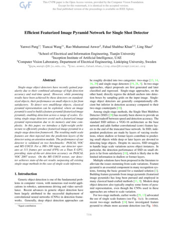
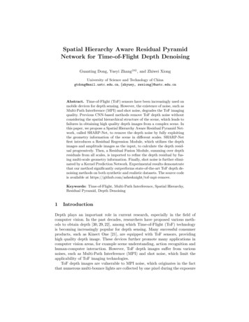
2G. Dong, Y. Zhang and Z. XiongFig. 1. (a) ToF amplitude image. (b) ToF ground truth depth. (c) Depth error mapcaused by shot noise. (d) Depth error map caused by MPI. The example comes from asynthetic dataset.time. The existence of MPI breaks the key assumption that the receiving lightis only reflected once in the scene and results in serious ToF depth error. Shotnoise, a common and inevitable noise caused by sensor electronics, is anothersource of ToF depth noise. Fig. 1 shows the depth error maps caused by shotnoise and MPI noise respectively. It can be seen that both shot noise and MPInoise are widespread in ToF depth images but MPI noise is significantly intensein several regions such as corner and edge areas.Recently, many Convolutional Neural Networks (CNN) based methods havebeen proposed for MPI removal in ToF sensors [17, 23, 26]. The fundamentaltheory of these CNN based methods is that the MPI noise of a pixel can beestimated as a linear combination of information from surrounding pixels. Inthe image space, CNN is a proper way to model this linear combination processwith spatial convolution and achieves encouraging results. To fit the unknownparameters of convolution kernel, supervised learning is often utilized and theground-truth labels without MPI of scenes are required. Since it is difficult toget the ground truth depth of realistic scenes, many synthetic ToF datasets areintroduced for the training and testing of neural networks. Usually, these datasetsconsist of ToF depth images as well as corresponding amplitude images. Somedatasets even contain the raw measurements of ToF sensors and color images,both of which are usually captured by the calibrated RGBD camera.The large-scale datasets make it possible to learn the linear combinationprocess of light transport through CNN based methods. However, the existingCNN based methods still have some limitations. Especially, the elimination ofMPI noise for a complex scene is not satisfying. Specifically, in a complex scene,many objects with different shapes and sizes are located close to each other.In this case, each pixel of the ToF sensor may collect many light signals whichare from various indirect light paths, which easily leads to intense MPI noise.Eliminating MPI noise in a complex scene still remains a challenging problemand needs more investigation.A key observation is that in a scene, the objects usually have spatial hierarchical structures. For example, a showcase, a dog toy and the head of the dog toycan formulate a hierarchical relationship. In this case, the depth value of a pointlocated at the surface of any object is usually affected by these three interrelated objects. In a complex scene with large-size shapes and detailed structures,
SHARP-Net3there should be more diverse hierarchical relationships. And previous works havedemonstrated that utilizing the hierarchical representations of the scene can leadto improvement in computer vision filed such as scene understanding [24, 27],image embedding [4], image denoising [20], object detection [19], depth and 3Dshape estimation [6, 18]. Aforementioned works inspire us to explicitly utilize thespatial hierarchical relationships to improve the result of the MPI removal forToF depth.In this paper, we propose a Spatial Hierarchy Aware Residual Pyramid Network (SHARP-Net) to fully exploit scene structures in multiple scales for ToFdepth denoising. The spatial hierarchical structure of the scene, in the formsof a feature pyramid with multiple scales, can provide a proper receptive fieldand more ample geometric relationships between the objects of the scene for thenetwork, which improves the performance of noise removal.Within SHARP-Net, a Residual Regression Module is first introduced, whichconsists of a feature extractor to build a feature pyramid and residual regressionblocks to establish a depth residual pyramid in a coarse-to-fine manner. At upper levels of the residual pyramid, the depth residual maps represent MPI noiseregressed by utilizing global geometry information. At lower levels, the depthresidual maps describe subtle MPI effects by considering local scene structures.The Residual Regression Module pushes every level to utilize the available hierarchical relationships of the current level and deeply extracts the geometricinformation lying in the corresponding hierarchy of the scene. The geometricinformation obtained in different scales give excellent hints for estimating theMPI noise. Our proposed Residual Regression Module generates a depth residualmap for each level, which is much different from the widely used U-Net structure.After going through Residual Regression Module, a depth residual pyramid isobtained to represent MPI estimation corresponding to the hierarchical structure of the scene. In order to further optimize the performance of SHARP-Neton both large-size shapes and detailed structures, we propose a Residual Fusion Module to explicitly choose predominant components by summing over thedepth residuals from all scales. Finally, we employ a Depth Refinement Module,which is based on a Kernel Prediction Network, to remove shot noise and refinedepth images.Combining the Residual Regression Module, Residual Fusion Module andDepth Refinement Module, our SHARP-Net accurately removes noise for ToFdepth images, especially MPI noise and shot noise. In short, we make the following contributions:– We propose a Residual Regression Module to explicitly exploit the spatialhierarchical structure of the scene to accurately remove MPI noise and shotnoise in large-size shapes and detailed structures simultaneously.– We propose a Residual Fusion Module to selectively integrate the geometricinformation in different scales to further correct MPI noise, and introduce aDepth Refinement Module to effectively eliminate the shot noise.
4G. Dong, Y. Zhang and Z. Xiong– The proposed SHARP-Net significantly outperforms the state-of-the-art methods in the quantitative and qualitative comparison for ToF depth denoisingon both the synthetic and realistic datasets.2Related WorkToF imaging is affected by noise from different sources, such as shot noise andMPI noise [15, 28]. Shot noise is caused by sensor electronics, which appears inall sensors. Shot noise removal for ToF sensors is well investigated. Traditionalfiltering algorithms, such as bilateral filtering, are able to eliminate shot noiseeffectively [2, 16]. In contrast, MPI removal is a more difficult problem in ToFdepth denoising. Many physics-based and learning-based MPI removal methodshave been proposed.For physics-based methods, Fuchs et al. conduct a series of studies to estimateMPI noise in the scene, from using single modulation frequency [9] to consideringmultiple albedos and reflections [10, 14]. Feigin et al. propose a multi-frequencymethod to correct MPI through comparing the pixel-level changes of the rawmeasurements at different frequencies [5]. Gupta et al. study the impact of modulation frequencies on MPI and propose a phasor imaging method by emittingtwo signals with frequencies of great differences [12]. Freedman et al. proposea model based on a compressible backscattering representation to tackle themulti-path with more than two paths and achieve real-time processing speed [8].For learning-based methods, Marco et al. exploit the transient imaging technology [13] to simulate the generation of MPI noise in ToF imaging process andproduce a large dataset for ToF depth denoising. They also propose a two-stagedeep neural network to refine ToF depth images [17]. Su et al. propose a deepend-to-end network for ToF depth denoising with raw correlation measurementsas the input [26]. Guo et al. produce a large-scale ToF dataset FLAT, and introduce a kernel prediction network to remove MPI and shot noise [11]. To overcomethe domain shift between the unlabelled realistic scene and the synthetic training dataset, Agresti et al. exploit an adversarial learning strategy, based on thegenerative adversarial network, to perform an unsupervised domain adaptationfrom the synthetic dataset to realistic scenes [2]. Qiu et al. take into account thecorresponding RGB images provided by the RGB-D camera and propose a deepend-to-end network for camera alignment and ToF depth refinement [23].Recently, residual pyramid methods have been adopted for a variety of computer vision tasks. For stereo matching, Song et al. build a residual pyramid tosolve the degradation of depth images in tough areas, such as non-texture areas, boundary areas and tiny details [25]. For the monocular depth estimation,Chen et al. propose a structure-aware residual pyramid to recover the depthimage with high visual quality in a coarse-to-fine manner [6]. For image segmentation, Chen et al. propose a residual pyramid network to learn the main andresidual segmentation in different scales [7]. For image super-resolution, Zhenget al. employ a joint residual pyramid network to effectively enlarge the receptive fields [31]. Our SHARP-Net refers to residual pyramid methods as well and
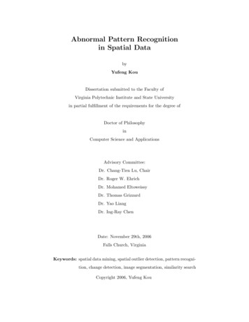
SHARP-Net5achieve success in ToF depth denoising, which will be explained in detail of thefollowing sections. To the best of our knowledge, SHARP-Net is the first work toapply residual pyramid to ToF depth denoising, which greatly surpasses existingmethods by integrating spatial hierarchy.3ToF Imaging ModelIn this section, we briefly introduce the mathematical models of ToF imagingand MPI.With a single modulation frequency fω and four-step phase-shifted measurements ri (i 1, 2, 3, 4), the depth d at each pixel is computed as r4 r2c,(1)arctand 4πfωr1 r3where c is the speed of light in the vacuum. Under the ideal condition, it isassumed that a single light pulse is reflected only once in the scene and capturedby a pixel (x, y) on the sensor. So the raw correlation measurement ri can bemodeled asZTs(t)b cos(ωt ψi )dt,ri (x, y) (2)0where s(t) is the received signal, b cos(ωt ψi ) is the referenced periodic signal,ψi is the phase offset and T is the exposure temporal range.In real world, MPI noise always exists. In this case, the received signal ischanged to ŝ(t), which can be described asXŝ(t) s(t) sp (t),(3)p Pwhere P is the set of all the light paths p followed by indirectly received signals.Here indirectly received signals sp (t) represent the captured signals which arereflected multiple bounces after being emitted to the scene. The difference between s(t) and ŝ(t) further leads to a deviation to the depth d. In our proposednetwork, we call this deviation the depth residual. To better regress the depthresidual, we bring in a residual pyramid to estimate MPI noise in multiple scales.At different levels of the pyramid, the deviation induced by the set P is regressedand further optimized by our network.4Spatial Hierarchy Aware Residual Pyramid NetworkOur proposed Spatial Hierarchy Aware Residual Pyramid Network (SHARPNet) consists of three parts: a Residual Regression Module as the backbonefor multi-scale feature extraction, a Residual Fusion Module and a Depth Refinement Module to optimize the performance. The flowchart of SHARP-Net isshown in Fig. 2. The following subsections explain these three parts respectively.
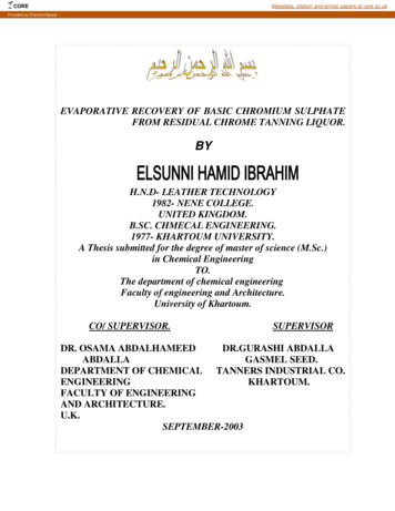
6G. Dong, Y. Zhang and Z. XiongFig. 2. Flowchartof Spatial Hierarchy Aware Residual Pyramid Network (SHARPJNet).LHeremeans the dot product operation, is the concatenate operation,andrepresents the addition operation. The ‘Patch2Vec’ represents the operation toreshape the neighbourhoods of each pixel to a vector.4.1Residual Regression ModuleAs the backbone of SHARP-Net, Residual Regression Module first introducesLa feature encoder to extract a multi-scale feature pyramid {Fi }i 1 from thecombination of depth image Din and amplitude image A, where Fi indicatesthe feature map extracted at the ith level, and L is the number of layers in thepyramid. When the size of the input image is W H, the size of feature mapsHat the ith level is 2Wi 1 2i 1 Ci , where Ci is the number of output channels.In our network, we set L 6 to keep the amount of parameters similar to thatof state-of-the-art methods. The corresponding Ci are 16, 32, 64, 128, 192, 256respectively. From bottom to top, the feature pyramid gradually encodes thegeometric information of the more detailed structure in the scene.At each level, a Residual Regression Block, as shown in Fig. 3, is proposedto predict the depth residual map. The depth residual map from the lower levelRi 1 is upsampled by the factor of 2 via bi-cubic interpolation, and then concatenated with the feature map at the current level. The new concatenated volume isthe input of five sequential convolutional layers, which output the residual mapRi for the current level. Specifically, for the bottom level, the input of ResidualHRegression Block is only the feature map with size W32 32 256 because there is
SHARP-Net7Fig. 3. Flowchart of Residual Regression Block at the ith levelno depth residual map from the lower level. Different from the previous method[23] that directly regresses a residual map by sequentially up-sampling featuremaps, our Residual Regression Module progressively regresses multi-scale residual maps in a coarse-to-fine manner by considering the hierarchical structures ofthe scene. The residual maps in lower resolutions depict depth noise existing inlarge-size shapes, while the residual map in higher resolutions focuses on depthLnoise existing in detailed structures. Finally, we get a residual pyramid {Ri }i 1consisting of the depth residual map at each level.4.2Residual Fusion ModuleThe uppermost level of the residual pyramid provides a depth residual map withthe original resolution, which can be treated as an estimation of the depth error. However, depth residual map from a single level cannot fully utilize thegeometry information of the scene. Although the uppermost level of the residualpyramid contains the information from all the levels below, after the convolutional operation, information from lower resolution levels may get lost. Thus,we propose a Residual Fusion Module to explicitly combine the depth residualmaps in all scales. The depth residual map at each level is first upsampled tothe original resolution via bi-cubic interpolation. Then all the upsampled depthresidual maps are concatenated together. The new residual volume is the inputof a 1 1 convolutional layer. After the convolutional operation, we get the finaldepth residual map Rout . The depth residual map is added to the original inputdepth image, by which the depth image is recovered as Dinter . The details ofResidual Fusion Module are shown in Fig. 2.4.3Depth Refinement ModuleAfter previous two modules, MPI noise is removed to a great extent. In themeantime, shot noise also gets alleviated, but not as much as MPI removal. Theexistence of shot noise still hinders the application of ToF depth sensing. Toaddress this problem, we propose a Depth Refinement Module, which utilizesKernel Prediction Network [3] to further remove shot noise.
8G. Dong, Y. Zhang and Z. XiongDepth Refinement Module takes the intermediate depth image Dinter as theinput, and employs a U-Net model with skip connection to generate a weightmatrix. The weight matrix consists of a vectorized filter kernel for each pixel inthe depth image. In our experiment, we set the kernel size k as 3 and the size ofthe weight matrix is W H 9. Next, we generate a patch matrix by vectoringa neighbourhood for each pixel in the depth image. We call the above operation‘Patch2Vec’. When the neighbourhood is a 3 3 area, it is easy to calculatethat the size of the patch matrix is also W H 9. Then the weight matrix ismultiplied element-wisely with the patch matrix, generating a 3D volume withthe same size. By summing over the 3D volume, we finally get the refined depthimage Dout . Fig. 2 shows details of Depth Refinement Module as well.4.4Loss FunctionTo train the parameters in our proposed SHARP-Net, we need to computethe differences between the predicted depth image Dout and the corresponding ground truth depth image Dgt . The loss function should guide our networkto accurately remove depth noise while preserving geometry details. Following[23], our loss function has two components, which are L1 loss and its gradientson the refined depth image. The formulation of the loss function is depicted asL 1 XkDout Dgt k1 λ k Dout Dgt k1 ,N(4)where k·k1 represents the L1 norm, and N is the number of pixels. Here discreteSobel operator is utilized to compute the gradients. In our experiments, we setλ 10.55.1ExperimentsDatasetsOur SHARP-Net is a supervised neural network to remove the noise for ToFdepth images. To train all the parameters, we need ToF datasets with groundtruth depth. To produce a suitable dataset, the mainstream method is applyingthe transient rendering technology to simulate the ToF imaging process whileintroducing MPI and shot noise [13]. Previous CNN based methods on ToF denoising have provided several synthetic datasets with thousands of scenes. In ourexperiments, we select two large-scale synthetic datasets ToF-FlyingThings3D(TFT3D) [23] and FLAT [11] for training and evaluation. The TFT3D datasetcontains 6250 different scenes such as living room and bathroom. We only utilize the ToF amplitude images and ToF depth images with resolution 640 480as input for our proposed method. The FLAT dataset provides a total of 1929scenes, which include the raw measurements and the corresponding ground truthdepth. By using the pipeline released by the FLAT dataset, we convert the rawmeasurements to ToF depth images and ToF amplitude images with resolution
SHARP-Net9424 512. Furthermore, to evaluate the performance of SHARP-Net on realisticscenes, we also adopt the True Box dataset which is constructed by Agresti etal. in [2]. The ground truth depth of the True Box dataset is acquired by anactive stereo system jointly calibrated with a ToF sensor. In total, there are 48different scenes with resolution 239 320 on the dataset.5.2Data Pre-processingWe normalize the input depth images according to the range of depth valueprovided by the dataset, and filter out the pixels whose depth value are notwithin the range (0, 1]. For the convenience of experiments, we crop the imageson the TFT3D dataset and FLAT dataset to size 384 512. For the True Boxdataset, we crop the images to size 224 320. In addition, for the FLAT dataset,we exclude scenes without background following the experiment setting in [23].For all the three datasets, we randomly select 20% scenes as the test set whilethe rest for training.5.3Training SettingsFor the TFT3D dataset, the learning rate is set to be 4 10 4 , which is reduced30% after every 2 epochs. We trained SHARP-Net for 40 epochs with a batch sizeof 2. For the FLAT dataset, we set the learning rate as 1 10 4 with conductingthe rate decay. We train the SHARP-Net for 100 epochs with a batch size of8. For the True Box dataset, the training settings are consistent with that ofthe TFT3D dataset. The network is implemented using TensorFlow framework[1] and trained using Adam optimizer. With four NVIDIA TITAN Xp graphicscards, the training process takes about 20 hours for both TFT3D and FLATdatasets, less than half an hour for the True Box dataset.5.4Ablation StudiesSHARP-Net is a CNN based method with a 6-level Residual Regression Module as the backbone and two extra fusion and refinement modules. In order tovalidate the effectiveness of our proposed modules, we design experiments tocompare SHARP-Net against its variants.– WOFusRef: A variant of SHARP-Net without the Depth Refinement Moduleand the Residual Fusion Module.– WORefine: A variant of SHARP-Net without the Depth Refinement Module.– WOFusion: A variant of SHARP-Net without the Residual Fusion Module.– FourLevel: A variant of SHARP-Net whose backbone has 4 levels.– FiveLevel: A variant of SHARP-Net whose backbone has 5 levels.For a fair comparison with FourLevel and FiveLevel, we need to ensure thatthe amount of parameters of these two variants are nearly the same with SHARPNet. Therefore, we adjust the number of convolution kernel channels of thevariants.
10G. Dong, Y. Zhang and Z. XiongTable 1. Quantitative comparison with the variants of SHARP-Net on the lFiveLevelSHARP-Net1st 0.09/5.8%TFT3D Dataset:MAE(cm)/Relative Error2nd Quan.3rd Quan.4th /5.1% 0.67/5.8% 8/14.5%1.53/12.5%1.19/9.7%For the quantitative comparison, we use two metrics, Mean Absolute Error(MAE) and relative error, to evaluate the performance. The MAE between theoriginal noisy depth image and the ground truth depth image is depicted as theoriginal MAE. Then, we define the relative error as the ratio of the MAE ofeach method to the MAE of the corresponding input. The overall and partialMAE/Relative Error at each error level are also calculated. Different denoisingmethods may have varying performances at different error levels. In our experiment, we adopt an evaluation method that is similar to the method in [23]to comprehensively evaluate our proposed SHARP-Net at different error levels.First, we calculate the per-pixel absolute error value between the input depthimage and the ground truth. Then we sort all the per-pixel absolute errors in anascending order. Next all the pixels in the test set are split into four quantiles(four error level sets). The difference between our evaluation method and themethod in [23] is that we sort all the pixels in the test set instead of in a singleimage. This change makes our evaluation more reasonable because sorting inthe whole test set eliminates the depth distinction over images. The pixels inthe range of 0%-25% are classified into the 1st error level. In the same way, thepixels in the range of 25%-50% and 50%-75% and 75%-100% are classified intothe 2nd, 3rd, and 4th error level. Pixels with depth value beyond the maximumdepth for each dataset are considered as outlier here and excluded from any errorlevel sets. Finally, we calculate the partial MAE and overall MAE for differenterror levels respectively.For ablation studies, we just utilize the TFT3D dataset to compare ourSHARP-Net against its variants. The overall MAE and partial MAE at each errorlevel are reported in Table 1. From Table 1, it can be observed that SHARP-Netachieves the lowest MAE and relative error at all error levels. In addition, ‘4thQuan.’ contributes the greatest share on the value of overall MAE comparedwith the remanent three quantiles. Comparing SHARP-Net with FourLevel andFiveLevel variants, we can see that at all error levels, MAE decreases as thetotal number of pyramid levels increases. This is because the network explicitlydivides the scene into a more detailed hierarchical structure if the pyramid hasmore levels, which results in a more accurate estimation of MPI noise.
SHARP-Net11Table 2. Quantitative comparison with competitive ToF depth denoising methods onTFT3D, FLAT and True Box datasets.ModelDeepToFToF-KPNSHARP-Net1st Quan.0.47/30.1%0.19/12.2%0.09/5.8%TFT3D Dataset: MAE(cm)/Relative Error2nd Quan.3rd Quan.4th Quan.Overall1.56/26.6% 3.11/27.0%9.01/30.0%3.54/28.9%0.82/13.9% 1.87/16.2%6.64/21.3%2.38/19.4%0.30/5.1% 0.67/5.8% 3.40/11.3% 1.19/9.7%FLAT Dataset: MAE(cm)/Relative Error1st Quan.2nd Quan.3rd Quan.4th Quan.OverallDeepToF0.09/27.3% 0.44/33.6% 1.13/43.5% 2.74/37.8% 1.10/43.3%ToF-KPN0.08/24.2% 0.30/22.9% 0.66/25.4% 2.12/29.3% 0.79/31.1%SHARP-Net 0.04/12.1% 0.14/10.7% 0.32/12.3% 1.33/18.4% 0.46/18.1%ModelTrue Box Dataset: MAE(cm)/Relative Error1st Quan.2nd Quan.3rd Quan.4th Quan.OverallDeepToF0.31/42.5% 1.06/49.5% 2.15/52.9% 5.75/53.9% 2.32/52.7%ToF-KPN0.28/38.4% 0.87/40.6% 1.64/40.4% 4.51/42.3% 1.82/41.4%SHARP-Net 0.15/20.5% 0.47/21.9% 0.91/22.4% 3.02/28.3% 1.14/25.9%ModelFig. 4. The per-pixel error distribution curves of different methods on the TFT3D,FLAT and True Box datasets. The distribution curves of these three methods show thatour proposed SHARP-Net obtains the optimal error distribution on all the datasets.Comparing SHARP-Net with WORefine and WOFusion, it can be observedthat the employment of Residual Fusion Module and Depth Refinement Module reduce the overall MAE by 26% and 23% respectively, which indicates thenecessity of those two modules. Linking the comparison between WORefine andWOFusion at all error levels, it can be seen that either of the two modules facilitates the decline of MAE but the extent is limited. However, considering thedifference between WOFusRef and SHARP-Net on the MAE and relative error,we conclude that utilizing these two modules together can greatly improve theperformance of the noise removal at all error levels.
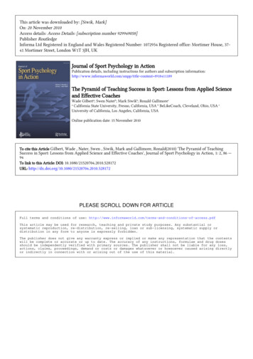
125.5G. Dong, Y. Zhang and Z. XiongResults on Synthetic DatasetsTo evaluate the performance of our proposed SHARP-Net, we compare it withtwo state-of-the-art ToF depth denoising methods DeepToF [17] and ToF-KPN[23]. The inputs of all selected methods are the concatenation of depth images and corresponding amplitude images. It should be noted that the originalDeepToF is smaller than SHARP-Net in term of model size. For a fair comparison, we take the same strategy as [23] to replace the original DeepToF modelwith the U-Net backbone of ToF-KPN. The quantitative experimental resultson the TFT3D and FLAT datasets are reported in Table 2. It can be seen thatSHARP-Net achieves the lowest MAE and relative error at all error levels of thetwo synthetic datasets. The MAE between the input depth and ground truthdepth is 12.24 cm and 2.54 cm for both TFT3D and FLAT datasets. Aftertraining on these datasets, SHARP-Net reduces the MAE to 1.19 cm and 0.46cm in the test sets respectively.The relative error is also a good indicator to measure the performance fordifferent methods. From Table 2, it can be seen that the DeepToF method givessimilar relative errors for all the four error levels, especially on the TFT3Ddataset. Compared with two other methods, DeepToF’s performance in terms ofthe relative error indicator is low. For ToF-KPN, the relative error increase as theerror level increasing, which means ToF-KPN has better denoising performancefor higher error level sets. For SHARP-Net, it can be seen that relative error ismuch smaller than the other two methods on the TFT3D dataset. on the FLATdataset, SHARP-Net is much better than DeepToF in term of relative error.Compared with ToF-KPN, SHARP-Net performs the same as ToF-KPN at thepreceding three error levels, and outperform ToF-KPN at the highest error level.For an intuitive comparison, in Fig. 4, we illustrate the per-pixel error distribution curves for all the methods on the TFT3D and FLAT datasets. It can beseen that after denoising by our SHARP-Net, the depth errors are mainly concentrated in the lower error region. In Fig. 5, we give several qualitative comparison results for SHARP-Net, ToF-KPN and DeepToF. It can be seen thatthe depth image corrected by our proposed method is more accurate, preserving more geometry structures in the scene. We observe that ToF-KPN performsbetter than DeepToF in removing the noise existing in detailed structures. However, the noise removal of
achieve success in ToF depth denoising, which will be explained in detail of the following sections. To the best of our knowledge, SHARP-Net is the rst work to apply residual pyramid to ToF depth denoising, which greatly surpasses existing methods by integrating spatial hierarchy. 3 ToF Imaging Model In this section, we brie