Transcription
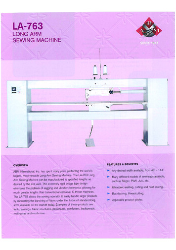
LA-763: V1.1TABLE OF CONTENTS:IntroductionSection 1.0 – SafetySection 2.0 - Machine SetupSection 3.0 – Machine OperationSection 4.0 – Troubleshooting guide and notebookSection 5.0 – Parts ListFigure 0.1 – LA-7631
LA-763: V1.1IntroductionABM International would like to thank you for the purchase of an LA-763 Long ArmSewing Machine. ABM is confident that this machine will meet or exceed yourexpectations for cost, speed and durability.If at anytime you experience problems with any of your ABM machines we ask that youcontact us - 24 hours a day by calling our service department at (281) 443-4440. We canhelp you solve the problem quickly, and correctly. Your calls, questions, and commentswill in turn help us to perfect the quality of our products and services in the future.Once again, we thank you for your purchase.ABM International, Inc.Joe PodolskiVice PresidentEngineering Department2
LA-763: V1.1Section 1: Safety1.0 Safety IntroductionAs with the operation of all machinery, safe operation of the LA-763 is a major concernof ABM International, Inc. The purpose of this section is to inform personnel of the safeand prudent operation of an LA-763.We have attempted to recommend the most effective methods and calculations to warnagainst actions that could result in personal injury, or make equipment unsafe. It isimportant to understand that ABM cannot anticipate, or list all conceivable safetymethods and warn of all the possible hazards. In the interest of promoting safety, ABMadvises that the operating personnel should always make sure that personal safety and thesafe operation of the machine will not be adversely affected by their actions.It is imperative that the operating personnel of the LA-763 read and understand theinformation in this manual before operating the machine.1.1 Safety Policy StatementThe conservation of the assets of any company, which include the buildings, equipment,supplies and inventories as well as personnel, must be and is the responsibility of alllevels of management. The purpose of a personnel and property conservation program isto insure that all phases of management recognize that personnel and propertyconservation are both inseparable parts of a company’s objective to produce qualityproducts at the lowest possible cost.Safety of personnel in every aspect must be of first consideration. The implementation ofa conservation program will eliminate human suffering and effectively lower the directand indirect costs resulting from employee injury. It will substantially reduce theexposure and probability of damage and / or loss of company’s physical assets.1.2 Safety PracticesThe safety factors must be observed to ensure safe operation of the LA-763 .1.2.3.4.5.6.Read and understand the operating instructions of the LA-763 before operating.Use extreme caution when working around the LA-763 electrical controls.Keep hands or other body parts away from the moving parts of the LA-763 .Wear appropriate personal safety protection.Stop the LA-763 immediately at any sign of malfunction or danger.Do not crawl under or into the LA-763 for any reason during the operation of themachine.7. Do not reach into the LA-763 at any time during the operation of the machine.8. Do not climb, walk, or stand on the LA-763 at any time.9. Do not tamper with factory installed guards and or safety devices.10. Never operate machinery without all ABM installed guards and safety devicesintact, and in working order.3
LA-763: V1.111. Before starting the LA-763, ensure that no loose tools, bars or parts are lying in oron any part of the machine.12. Proper fire fighting equipment should be kept in good operating condition andkept near in the event of fire.13. Never attempt to service any of the pneumatic components until the unit isrelieved of all air pressure.14. Do not wear loose clothing or jewelry when operating the LA-763.15. Always keep hair from coming in contact with moving parts.4
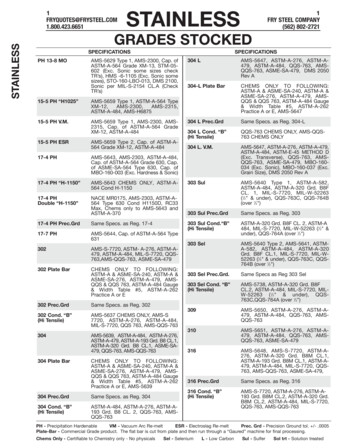
LA-763: V1.1SECTION 2.0 – Machine SetupThe LA-763 ships fully tested ready to operate. As a result, this manual provides asection on machine setup so that you can install the machine. Please read this manual inits’ entirety and follow all ABM instructions, especially the inspections. Total setup time,less power and air hook-up, should take approximately 1 hour.SETUP INSTRUCTIONS:INSPECTION #1: Upon receipt of the machine, check to ensure that there is no visibledamage. Figure 0.1 and the front cover of this manual are enough for this inspection.Note: that some components may be in different locations depending on the versionof the machine.Determine the location in your facility for the sewing machine. Attach the eight (8)machine legs supplied with the machine to the plates that were used to bolt the machineto its skid. Level and position the machine in the desired location. Though not required,ABM recommends that the machine be bolted to the floor. Place the foot pedal in frontof the machine on the floor and connect it.Run a 220VAC line (15AMP) to the machine location. Though the machine does notcome equipped with a 220V plug, “ABM” does not recommend the use of any type ofextension cord to power the machine. As with any machine, power should be runthrough approved conduit and ducting with proper termination. ABM does not supply amain power disconnect with the machine and recommends that the customer install one.You may connect the power to the machine at this time.INSPECTION #2: Will confirm that the electronics of the LA-763 long arm sewingmachine are functioning properly.WARNING: ELECTRICAL SHOCK HAZARD. THIS INSPECTION WILLREQUIRE POWER TO BE ON WHILE THE ELECTRONICS CABINET ISOPEN. IF A PROBLEM IS FOUND, YOU SHOULD NOT ATTEMPT TOREPAIR IT WITH THE POWER ON. DISCONNECT THE MACHINE PRIORTO ADJUSTING ANY COMPONENTS WITHIN THE ELECTRICAL CABINET.Step one; open the electronics cabinet located on the right vertical end-stand of the steelbridge of the machine. The internals of the cabinet will look like Figure 1.0. From top tobottom the components are as follows: Lamp power supply, servo motor, servo motioncontroller .Upon power up, the sewhead needles up.5
LA-763: V1.1Figure 2.0 – Electrical Panel.FINAL TEST:WARNING – WHEN OPERATING THE MACHINE, YOU MUST ENSURETHAT THERE ARE NO LOOSE ITEMS SUCH AS TOOLS FOOD DRINKS ETC.ON THE MACHINE AND THAT ALL PESONNEL ARE CLEAR OF THEMACHINE.6
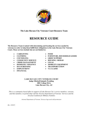
LA-763: V1.1Figure 2.1 – LA-763 sewing head.Inspect the front of the machine and ensure that the sewhead is free of obstructions.Step 1: Depress the treddle forward and the sewhead will begin to run.Step 2: Release the treddle and the needle will stay down to pivot your fabric.Step 3: Depress the treddle backwards and the needle will raise to the upper position.Setup and inspection is now complete.7
LA-763: V1.1SECTION 3.0 – Machine OperationThis section will discuss how to properly use the LA763 to fulfill all of your sewingneeds.The LA-763 is equipped with either a mechanical or pneumatic foot lifter to createclearance under the foot when inserting and removing your product to be sewn.For the mechanical lifter:Figure 3.0 – Foot Lifter Operation.To raise the presser foot, pull down on the white presser foot lift lever at located at theback of the sewhead. To release the presser foot, pull the silver release bar located at thetop of the back of the sewhead.For the pneumatic lifter:Figure 3.1 – Pneumatic foot lift OperationToggle switch mounted to the left of the sewing head will raise and lower the foot.8
LA-763: V1.1Operating the LA-763 is a simple task. Turn the main power on and allow the machine toenergize (this may take 5 seconds). While the machine is powered on please make surethat the foot pedal is not being pressed or the machine will activate an electrical safetymeasure that will not allow the sewhead to work. To reset the safety, turn off themachine remove anything that may be activating the pedal and turn the machine on.Figure 3.2 – Power DisconnectThe speed of sewing can be adjusted two ways. The first is via the foot pedal. Pressingthe pedal further will cause the machine to speed up and releasing pressure will make themachine slow down.Figure 3.3 – Foot pedal control9
LA-763: V1.1Speed can also be limited on the servo controller interface. Press the TE SPEED buttonuntil the menu with speed is shown. Press the four lower arrow keys to increase ordecrease the desired maximum speed. When modification is complete, press TE SPEEDto store the number in memory.Figure 3.5 – Servo motor controller interface10
LA-763: V1.1SECTION 4.0 – Troubleshooting guideABM has done its best to include as much information as possible. However, not allproblems are listed, therefore ABM asks that whenever a problem occurs you contact aservice technician at our home office. To reach service dial 281-443-4440 and ask for aservice technician, they are on call 24 hours a day, seven days a week.Troubleshooting notes:A few blank pages are provided so that you and your personnel can keep records andnotes of machine problems. By using this section and keeping it attached to the manual,you will always have your own personalized quick reference repair section.11
LA-763: V1.1TROUBLESHOOTING NOTES:DateProblemSolution12
LA-763: V1.1TROUBLESHOOTING NOTES:DateProblemSolution13
LA-763MLong Arm machine manual: Electric versionswww.abminternational.com Installation instructionsOperational guideTroubleshooting guideParts list
Table of Contents Section 1.0 Section 2.0 Section 3.0 -Machine Operation GuideTroubleshooting guideParts List
EcoDriveQE3760/QE5540Instruction ManualPart 1QUICK-ROTAN Elektromotoren GmbHKönigstraße 15467655 KaiserslauternTel: 0631 / 200 38 80Fax: 0631 / 200 38 62E-Mail: h 2004-03-10
Thesymbol confirms that the respective drive system meets theapplicable safety requirements of the following EU directives:- EC Maschine Directive 89/392/EWG- EMV Directive 89/336/EWG- Low Voltage Directive 73/23/EWGed-1-en04-03-10
ContentsPagePart 11.General Safety Information1.1 - 1.22.Technical Specifications2.1 - 2.33.Range of Application3.14.Scope of Supply3.15.Transport and Storage3.16.6.16.26.36.46.5Mounting InstructionsMounting of the MotorAdjustment of the motor and machineElectrical connectionPreventive Action Against Electrostatic ChargesMounting of Speed Control Unit (SWG)6.1 - 6.7Part 27.Construction and Description of the EcoDrive Drive System8.Application9.Programming by the User10.Start of OperationPart 311.Survey and List of Parameters12.Electrical Connections DiagramTechnical updatings reserved !ed-1-en04-03-10
1.General Safety InformationThis EcoDrive Sewing Drive System has been constructed and tested in compliance with the relevantregulations and safety standards and has left our factory in proper safety condition.In order to maintain this condition and to ensure non-hazardous operation, the user is obliged toobserve the information and warning notes contained in this Operating Instructions Manual.The EcoDrive is not a ready-to-use machine, but is designed for installation into machines of the sewingthread processing industry operating in clean and dry localities. It is not allowed to operate theEcoDrive in any machine unless the machine destined for receiving installation of this motor isspecifically identified as being in compliance with the regulations of the EC Rule on machines.Any application or use beyond the conditions stipulated above, such as outdoors, in moist or explosionhazardous environment, is not considered to be in compliance with specifications. Application incompliance with regulations and standards also includes close observation of the operating, maintenanceand repair conditions stipulated by the manufacturer.The EcoDrive can function safely and reliably only when used in compliance with this OperatingInstructions Manual and in compliance with the use it is intended for.Read this Operating Instructions Manual thoroughly before unpacking and commissioning the ECODRIVE. Please make yourself acquainted with all safety, installation. operating and maintenanceinstructions before starting operation of the EcoDrive, its accessories and attachments.Any and all activities on and by means of the EcoDrive must be carried out exclusively under closeobservation of the general and specific safety instructions given in the ensuing sections of thisOperating Instructions Manual!All persons involved must be made thoroughly familiar with these safety instructions, requiring them toobserve these closely. Non-observation of these safety instructions can cause injury to persons,damage to objects or malfunction of or damage to the drive system itself.Any and all accident prevention regulations as well as the rules on work in compliance with properpractices and safety standards valid in the user country involved must be fully observed. This drivesystem is subject to installation and commissioning by properly trained personnel!Installation and commissioning of the EcoDrive must be made with due care by qualified technicians soas to minimize the effects of any disturbing influences which are likely to constitute health hazards topersonnel or any other perilous condition.Doing any work on any parts or elements of the equipment being under live voltage is not permitted!Exceptions are subject to EN 50110.Before removing any cover parts or installing any attachments or accessories - such as speed controlunit, light barrier control etc. - switch the machine off, shut off physical connection with mains voltage,and wait for the machine to come to complete stop. Do not open the control box before ten minutes haveelapsed!In order to reduce any hazard of burns, fire, electrical shock, or injury, it is basically not permitted to makeany structural modifications or other changes on the EcoDrive.It is not allowed to operate the equipment with any cover or protection elements removed!Before leaving the workplace, turn the ON/OFF switch into its OFF position. In case of prolonged pausesof operation, remove the mains plug from the wall oulet so as to safeguard the drive system againstbeing inadvertantly switched on again.Any equipment or auxiliary facilities additionally connected to the control system of the EcoDrive are onlyallowed to be operated on low voltage generated by a safety transformer!Never use the drive system with its ventilation louvers clogged. Make sure that ventilation louvers areunobstructed by fibres, lint, dust etc.ed-1-en1.104-03-10
Do not introduce or drop any objects, such as needles, into the ventilation louvers.Keep your hands out of the area of moving parts!Do not operate the EcoDrive when using aerosols (sprays) or oxygen!This Operating Instructions Manual is an integral part of the EcoDrive and must be passed on with it incase of change of ownership.The instructions given in the sections below are destined for your own safety as well as for that of otherpersons.Warnings given in various section of this Operating Instructions Manual for the purpose ofpreventing specific hazards of injury to persons or damage to the equipment are identifiedby the symbol shown at left.This symbol is a warning given on the EcoDrive, indicating dangerous voltage.The EcoDrive is permitted to operate only in a properly functional protection earth systemin compliance with all local rules and regulations.ed-1-en1.204-03-10
2.Technical SpecificationsRated Values:ED QE3760Voltage (UN) [V]EDL QE5540230, single phase ACFrequency (fN) [cps]50/60Current (drive system) (IN) [A]3,55,0Current (control system) [A]0,6Power (output) (P2) [W]375550Speed (nn) [1/min]60004000Torque (Mn) [Nm]0,631,2Moment of motor inertia (Jmot) [kgcm²](without belt pulley)0,51,0Operating modeS5 (40 % duty cycle at ts 2.5 s)Intermittent operation with electrical brake action,relative duty cycle 40 %, operating cycle time 2.5 sProtection typeIP40Insulation classELimit ValuesRange of voltage [V]190 - 240 /- 10% single phaseSpeed (n) [1/min]max9000Torque (accelleration) (Mmax, short-time) [Nm]Power (short-time) (P2max, short-time) [W]Maximum permissible (Jmasch) [kg cm²]sewing machine inertia,reduced to the motor shaft (Jmach)450037100015004,59,0Conditions of UseAmbient temperature [ C] 5 bis 45Ambient temperature (24 hour average) [ C] 35Humidity (relative)85% bei 30 CDriving voltage of the OutputsIdling voltage [V]25 DCVoltage under load [V]24 DC at I 4 amps(20 DC at I 10 amps short-time)Power96 (200, short-time)Load current4Maximum load current10, (short-time)Note: The accumulated load currents of all simultaneously operated outputs(solenoids, solenoid valves) are not allowed to exceed 4 amps!ed-1-en2.104-03-10
Dimensions of the Control System (small version) ED350,4254,2280505,511290,410102020350,4Control System (broad version) .204-03-10
Motorl1508015l280ed-1-en2.3MSMSLl1 179219l2 147,5187,504-03-10
3. Range of ApplicationThe EcoDrive is not a ready-to use machine, but is intended for installation into other machines, suchas sewing units and sewing equipment used by the sewing thread processing industry.The EcoDrive is destined for use in clean and dry localities.Any application or use beyond the conditions stipulated above, such as outdoors, in moist or explosionhazardous environment, is not considered to be in compliance with specifications.Application in compliance with regulations and standards also includes close observation of the operating,maintenance and repair conditions stipulated by the manufacturer.4. Scope of Supply1xSynchronous motor QE3760 with commutation transmitteror Synchronous motor QE5540 with commutation transmitter1xControl system with mains power switch1xSpeed control unit SWG2 (Art.Nr.63.012) accessories1xOperating Instructions ManualOptional:1Synchronizer (Art.Nr. 62.055)1Operator panel EcoTop5. Transport and StorageThe EcoDrive has left our factory after thorough final inspection.Please check the drive system for any transport damages.If necessary, file claims with the carrier.Complaints for missing parts will be accepted within 14 days from the date of purchase.The EcoDrive and its accessories are shipped in a carton with polyurethane insert;outside dimensions:L 600 mm,W 405 mmH 280 mmThis packing material protects the EcoDrive against outside influences duringtransport and storage.The EcoDrive is designed to withstand temperatures during transport and storageof between -25 C and 55 C and briefly, but not lon ger than 24 hours, up to 70 C.Storage in the packing material must be in a dry environment.Handle the carton and its contents with care!ed-1-en3.104-03-10
6. Mounting InstructionsBefore starting installation, please remove all parts from the packing material.The carton holds the EcoDrive, accessories and Operating Instruction manual.Check the content if complete.If you have any questions with the installation, not clarified through the Instruction Manual,please contact us or one of our nearest Service Stations.Assemble the EcoDrive in compliance with the instructions and illustrations.6.1 Motor assemblyThere are three different ways to assemble the motor to the machine.1.Machine head mount (rear / external)2.Under the table top mount3.Machine head mount (direct drive, internal)There are three different ways to transmit the motor drive:· Timing belt and timing gears.· “V” belt and pulley.· Direct drive on main shaft.6.1.1 Use of timing belt.Transmitting torque through timing belt, slippage is avoided.Transmission ratio between motor and machine is 1:1.Being so, no reference signal from sewing machine is required.Many transmission ratios in both directions are possible,on the available timing belt wheels.In this case a reference position signal is needed by the machine.6.1.2 Use of “V” beltTransmitting torque through “V” belt, slippage is possible. Transmission ratio between motor andmachine is variable. Reference signal from sewing machine is required.6.1.3 Assembly of the motor to the machine head.Following, list of parts required:- Assembly bracket (machine type related)- Motor timing gear- Machine timing gear- Timing belt- Belt cover6.1.4 Assembly of the motor under the tableFollowing list of parts required:- Assembly bracket- Motor pulley- Machine pulley- “V” belt- Belt cover- If necessary synchronizer PD3- Y-adaptered-1-en6.104-03-10
6.2 Motor and machine adjustmenta)Adjust motor shaft to reference position (zero position)- Terminal box at top (viewpoint)- Motor shaft groove (-90 ) quarter to twelve in re lation to terminalbox equals zero position, rotate motor shaft.b)Adjust machine reference position (zero position)- Rotate machine pulley (sewing rotation) until needle point startspenetrating needle hole of throat plate (zero position)c)Assembly of timing belt- Slide belt to motor and machine timing gear maintain and guaranteepositions described in a) and b).ed-1-en6.204-03-10
6.3 Electrical Connection (to Mains Power)All work on the electrical equipment (connection, maintenance, repair) is permitted to be performedonly by or under the supervision of a properly qualified technician.The EcoDrive is designed for connection to an earthed AC mains power system having a rated voltagebetween190 and 240 Volts, 50/60 cps.Before connecting the power supply line, make sure that your mains power voltage is within the ratedvoltage range specified on the nameplate of the EcoDrive.Connection to mains power is permitted only by means of a multi-contact plug with protection earthcontact. Fixed connection is not permitted.Connect the following potentials:Phase(L1 or L2 or L3)Neutral conductor (N)Protection earth (PE)The EcoDrive is designed for connection to the following types of mains power systems:- TN (system with a directly earthed point and with a protection earth conductor (PE) connected to thispoint)- TT (system with a directly earthed point, the protection earth conductor (PE) not being connected tothis point)- IT (system not directly -10
The following applies to TT and IT systems:All elements protected by a common protective device must be connected to the same earthing viaprotection earth conductors.All elements apt to be touched simultaneously must be connected to a common earthing.The following applies additionally to IT systems:No active conductor within the installation is permitted to be earthed directly. All elements must beconnected individually, in groups, or in total with a protection earthing conductor.Single-phase connector systemwith protection earth conductorDo not operate more than 5 EcoDrives on one circuit fused with 16 amps.Threephase connector system with protection earth conductorMake sure to distribute loads evenly in a threephase AC system!Do not operate more than 3 EcoDrives on one face fused with 16 amps in order not to overloadthe N-conductor!The EcoDrive is a protection class I device, i.e. for protection at indirect touching it comprises aprotection earth connection.The EcoDrive is permitted to operate only in a properly functional protection earth system incompliance with all local rules and regulations in order to avoid danger to persons by electricshock or fire hazards in case of malfunction.ed-1-en6.404-03-10
It is not permitted to disable the protection system by using extension cables not equipped with aprotection earth conductor.Caution:Any interruption of the protection earth conductor within the EcoDrive or outside, or bydisconnecting the protection earth connection, can result in making the equipmenthazardous.Any intentional interruption is inadmissible.Fault Current Protection DevicesIf any EcoDrives are to be monitored via fault current protection devices, then the latter must be shockpuls proof, short pulse delayed as well as suited for alternating and pulsating constant fault currents.For connections, use line types not lighter than plastic- insulated sheathed flexible cables H05 VV.The minimum conductor cross section must be 1 mm2, with the line length not in excess of 5 m.The voltage drop in the protection earth conductor is not permitted to exceed 3.3 V at a measuringcurrent of 10 amps.Any lines installed must be properly protected against anticipated loads and must be properly fastened.Place and attach lines so as to maintain a minimum distance of 25 mm relative to any moving parts.Place lines, mains power leads and low voltage circuits at a proper distance from each other to achieveadequate separation.For replacement make sure to use exclusively fuses of the type and current rating specified.Any bridging-over of fuses is inadmissible and will create electrical or fire hazards.If there is reason to presume that operation without hazards will not be possible, discontinue operation ofthe drive system and safeguard the equipment against inadvertant use.Reasons to presume that operation without hazards will not be possible are as follows:-if the drive system presents visible damage, for instance mains power connection cable,-if the drive system fails to function,-after lengthy storage at unfavourable conditions.The control box may be opened only by properly qualified personnel and after having separated the drivesystem from mains power by pulling the plug out. (After switching the system off, wait at least 10minutes.)Insert and lock carefully the connectors on the control system after having checked the pin and socketconfiguration and the plug-in direction, to avoid malfunction.The brake action will not be initiated when mains power supply is switched off or power failure occursduring operation of the EcoDrive.When leaving the workplace or when doing maintenance work, separate the machine frommains power by pulling out the plug. For this, do not pull at the cable, but grip the plug and pull itout.Before separating the EcoDrive from mains power,bring all control elements into „OFF“ or „0“ position.ed-1-en6.504-03-10
6.4 Electro-Magnetic Compatibility (EMC)The EcoDrive is designed for installation/attachment to EMC sewing units and equipment, i.e. it complieswith the relevant EMC regulations (CDV IEC 204-3-1 44 sec 169) for a cable length of 500 mm at eachinput or output connector. In accordance with experience, this is adequate for sewing units.More complicated sewing equipment may require additional action due to longer cables, unfavourablecable placement, neighbouring strong interference fields etc.The following action can be appropriate for reducing or eliminating interference:-The use of appropriate filters, delay units, line material or line placement.-Lines belonging to different circuits (such as mains power, low voltage) being placed at a properdistance from each other to minimize interference.-Reference potential conductors for the circuits, or a common connection point:star-type wiring with one or more reference points earthed via insulated conductors having a largecross section.-Electrically conductive parts of the sewing unit or equipment should be connected via potentialcompensation leads to the protection earth conductor on the EcoDrive control box. (Use leads suitedfor high frequencies: fine-gauge stranded leads with a cross section of at least 2.5 mm2, or largearea copper bands.)When connecting potential compensation leads, make sure to achieve good contact, i.e. use toothedwashers for connections to painted parts.Include the following parts in potential compensation:- sewing machine head- sewing machine stand- treadle- housings of solenoids or solenoid valves- holding brackets for push-button switches- stands for stackers, band feeders etc.-Mass ConnectionsLead mass connection lines from each equipment element to a common point.Use large cross section braided leads between moving parts and casings while keeping massconnection as short as possible.-Signal TransmissionUse electrostatic and magnetic screening, twisted conductors and appropriate line placement toensure that transmission of interference voltages from control or mains power lines to signal lines isprevented.(Right-angle line crossings are better than any lower angles; by all means avoid parallelplacement.)-Separation of Equipment PartsEquipment parts that are susceptible to interference parts (pulse-processing and/or low-levelsubassemblies) should be mounted separately from and/or be screened against switching devicessuch as electromagnetic relays, thyristors etc.-Although being largely insusceptible to interference, the EcoDrive should not be operated in theimmediate vicinity of HF welding devices or similar equipment to avoid malfunction.-The EcoDrive is capable of complying with EMC regulations only when the control box front isprovided with its cover!-The covers of the control box must remain closed during operation in order to avoid malfunction dueto EMC causes as well as pollution by dust penetration.Whenever trouble should occur, please contact the manufacturer.ed-1-en6.604-03-10
6.5 Mounting of the Speed Control Unit (SWG)-Attach the speed control unit by means of the mounting bracket under the machine table.-Connect the push/pull bar of the SWG with the machine treadle by means of a pitman rod.-Install the mounting bracket for the SWG in such a way that the pitman rod and the push/pullbar of the speed control unit (SWG) line up to the treadle.This guarantees a optimal force transmission from treadle to SWG.-The pitman rod and the treadle should form an angle as close to 90 degrees as possible.-The speed control unit can be swivelled on the control box within a range of 40 degrees.-Make sure that the treadle can move with ease!ed-1-en6.704-03-10
EcoDriveQE3760/QE5540TypeP40EDInstruction ManualPart 2QUICK-ROTAN Elektromotoren GmbHKönigstraße 15467655 KaiserslauternTel: 0631 / 200 38 80Fax: 0631 / 200 38 62E-Mail: tech.supp@quick-rotan.comwww.quick
SECTION 2.0 – Machine Setup The LA-763 ships fully tested ready to operate. As a result, this manual provides a section on machine setup so that you can install the machine. Please read this manual in its’ entirety and follow all ABM instructions, espec