Transcription
NXP SemiconductorsDocument Number: MBOOTDEMOUGUser's GuideMCU Bootloader Demo ApplicationsUser's GuideRev 3, 05/2018
ContentsContentsChapter 1 Introduction.3Chapter 2 Overview.42.1 MCU bootloader. 42.2 Host utility. 42.3 led demo user application.42.4 Host updater. 42.5 Toolchain requirement. 4Chapter 3 Getting Started with MCU bootloader application.63.1 Plug it in.63.1.1 Select a board. 63.1.2 Plug in the board. 63.1.3 OpenSDA. 63.1.4 PC Configuration. 63.2 Get Software.73.2.1 Go to MCUXpresso SDK Builder. 73.2.2 Build the SDK. 73.2.3 Install a Toolchain. 73.3 Build and Run. 83.3.1 Import the example. 83.3.2 Build the imported project. 103.3.3 Run blhost. 11Chapter 4 The host utility application. 14Chapter 5 Windows GUI updater application.155.1 Installing the user application. 15Chapter 6 Returning to Flash-resident bootloader. 19Chapter 7 Appendix A - MCU flash-resident bootloader operation.207.1 Memory map overview. 217.2 User application vector table. 227.3 Bootloader Configuration Area (BCA). 22Chapter 8 Appendix B - MCU Bootloader Development platforms. 23Chapter 9 Appendix C - MCU Bootloader Pin mappings.31Chapter 10 Revision history. 44MCU Bootloader Demo Applications User's Guide, Revision 3, May 20182NXP Semiconductors
IntroductionChapter 1IntroductionThis document describes how to use the MCU bootloader to load a user application on a Kinetis MCU.MCU Bootloader Demo Applications User's Guide, Revision 3, May 2018NXP Semiconductors3
OverviewMCU bootloaderChapter 2OverviewThis guide describes the steps required to use the NXP-provided MCU bootloader utilities to both load the MCU bootloaderimage and use the bootloader to update the user application section of flash. On reset, the bootloader detects the userapplication and launches it. The bootloader also provides a means to stop the application launch and remain in the bootloadercommand processor to refresh the user application. This full-circle environment enables application developers to easilyinstall new applications onto MCU devices. It also provides manufacturers a way to update MCU devices in the field withouta debugger.2.1 MCU bootloaderThe MCU bootloader serves as a standard bootloader for all Kinetis devices. It provides a standard interface to the devicevia all of the available peripherals supported on a NXP Kinetis device. The MCU bootloader interface is available in severalforms like ROM, serial flashloader, or a customized flash-resident bootloader. Some Kinetis devices have ROM containingMCU bootloader while others are pre-programmed from the factory with a one-time-use serial flashloader. For a customizedinterface, customers can leverage the MCU bootloader source code to create a unique flash-resident bootloader that is bothcompatible with tools that understand the bootloader interface, and are capable of supporting application-specific features.NXP provides utilities to demonstrate how to interface with the bootloader.2.2 Host utilityThe blhost.exe utility is a cross-platform host program used to interface with devices running the MCU bootloader. It lists andrequests the execution of all the commands supported by a given Kinetis device running the bootloader. Check blhost User'sGuide (document MCUBLHOSTUG) for detailed information.2.3 led demo user applicationThe led demo freedom/tower/maps base address projects are examples demo firmware applications used todemonstrate how the MCU bootloader can load and launch user applications. The demo projects can be found in sdk package /boards/ board /bootloader examples/demo apps/.2.4 Host updater The KinetisFlashTool.exe host application is a Windows OS GUI program used to update the user application image on thedevice running the MCU bootloader firmware application. For more information on the Kinetis Flash Tool application, see theKinetis Flash Tool User's Guide (document MBOOTFLTOOLUG).2.5 Toolchain requirementFirmware projects:MCU Bootloader Demo Applications User's Guide, Revision 3, May 20184NXP Semiconductors
OverviewToolchain requirement IAR Embedded Workbench for ARM v.8.20.2 or later Python v.2.7 (www.python.org) MCUXpresso IDE v10.1.1 Keil MDK v5.24a with corresponding device packsHost projects: Microsoft Visual Studio Professional 2015 for Windows OS Desktop Microsoft .NET Framework 4.5 (included in Windows OS 8) Microsoft Visual C Redistributable for Visual Studio 2015 (vcredist x86.exe) Apple Xcode v9.2 (for tools) GNU Compiler (GCC) v5.4.0 (for tools)MCU Bootloader Demo Applications User's Guide, Revision 3, May 2018NXP Semiconductors5
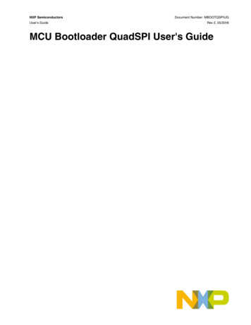
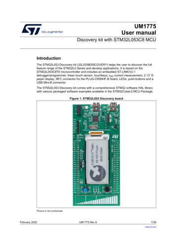
Getting Started with MCU bootloader applicationPlug it inChapter 3Getting Started with MCU bootloader application3.1 Plug it in3.1.1 Select a board Go to MCU Bootloader for Kinetis microcontroller and select the desired boards from "Supported Kinetis Devices" Take FRDM-K64F as an example for demoFigure 1.FRDM-K64F3.1.2 Plug in the boardConnect the board the PC via the USB cable between the OpenSDA USB port on the board and the USB connector on thePC.3.1.3 OpenSDAKinetis MCU boards are supplied with OpenSDA firmware pre-loaded. For software development on the MCU board, checkfor the latest OpenSDA driver is on the Freedom development board. This allows debugging, flash programming, and serialcommunication over a USB cable.Find the latest OpenSDA firmware for the boards here:OpenSDA Update to the boardsFor the example FRDM-K64, go to this website and choose board FRDM-K64 to get the latest OpenSDA firmware.3.1.4 PC ConfigurationThe output data from the provided example applications is provided over the MCU UART. This requires that the driver for theboard’s virtual COM port is installed. The board must be plugged into the PC before the driver installer is run.The links for the latest OpenSDA Windows serial port drivers are provided in the same web page:MCU Bootloader Demo Applications User's Guide, Revision 3, May 20186NXP Semiconductors
Getting Started with MCU bootloader applicationGet SoftwareOpenSDA Update to the boardsFor the example FRDM-K64, go to this website and choose board FRDM-K64. In the next web page, click on ARM CMSISDAP serial drivers to download Windows Serial Port Drivers.Once the Windows Serial Port Drivers are installed on the PC, determine the port number of the FRDM board’s virtual COMport by checking the "Ports" under Device Manager.NOTEAll the Serial Port Drivers are installed automatically when installing MCUXpresso IDE. Skip thisstep and jump to section 2 if you plan to install the MCUXpresso IDE.The demonstration board is now ready to communicate with the PC.3.2 Get Software3.2.1 Go to MCUXpresso SDK BuilderGo to MCUXpresso SDK Builder.Choose the desired development board and click on Build MCUXpresso SDK.In SDK Builder page, choose the desired Host OS and the IDE tool chain.Click on Add software component, select mcu-boot and middleware from drop-down list. (USB stack middleware should beselected if existing).For this example, FRDM-K64F board, Windows OS, MCUXpresso IDE, middleware mcu-boot and USB stack are selected.3.2.2 Build the SDKClick on Download SDK. A pop-up window SDK Downloads will show when the package is built successfully. Click onDownload SDK Archive to download the package. The package is provided as a zip file.3.2.3 Install a ToolchainNXP offers a complimentary toolchain called MCUXpresso IDE.Figure 2. MCUXpresso IDEThe MCU Bootloader includes support for other tools such as IAR and Keil.MCU Bootloader Demo Applications User's Guide, Revision 3, May 2018NXP Semiconductors7
Getting Started with MCU bootloader applicationBuild and Run3.3 Build and Run3.3.1 Import the example Install the downloaded FRDM-K64F SDK package into MCUXpresso IDE (Simply drag and drop the zipped SDK packageas it is to the “Installed SDKs” view).Figure 3.Install SDKsOnce the SDK installation is completed, click on ‘Import SDK examples’. In the SDK import wizard, choose FRDM-K64F as the available board for your project.MCU Bootloader Demo Applications User's Guide, Revision 3, May 20188NXP Semiconductors
Getting Started with MCU bootloader applicationBuild and RunFigure 4.Board and/or Device selection page Import freedom bootloader example from the list of available projects.Figure 5.Import projectsMCU Bootloader Demo Applications User's Guide, Revision 3, May 2018NXP Semiconductors9
Getting Started with MCU bootloader applicationBuild and RunNOTEOnce, the freedom bootloader example is imported successfully, the MCUXpresso IDEautomatically creates the corresponding standalone project in your workspace.3.3.2 Build the imported project Build the project by clicking build buttonFigure 6.Build project Load firmware by clicking on “Debug frdmk64fxx”MCU Bootloader Demo Applications User's Guide, Revision 3, May 201810NXP Semiconductors
Getting Started with MCU bootloader applicationBuild and RunFigure 7.Debug project3.3.3 Run blhost Before running blhost, get the port number of the FRDM board’s virtual COM port by opening the device manager andlooking under the "Ports" group.MCU Bootloader Demo Applications User's Guide, Revision 3, May 2018NXP Semiconductors11
Getting Started with MCU bootloader applicationBuild and RunFigure 8.Device Manager In downloaded package, Windows blhost is located at middleware\mcu-boot\bin\Tools\blhost\win.Open a command prompt and run blhost to to initiate communication and inject commands to the bootloader. For instance,you can connect to bootloader over UART with option "-p" and run blhost command get-property to get some informationfrom bootloader.Type blhost -p COM21 -- get-property 12 to get memory regions reserved by the bootloaderType blhost -p COM21 -- get-property 1 to get current bootloader versionSee MCU blhost User's Guide (Document ID: MCUBLHOSTUG) for additional information.MCU Bootloader Demo Applications User's Guide, Revision 3, May 201812NXP Semiconductors
Getting Started with MCU bootloader applicationBuild and RunFigure 9.Command PromptMCU Bootloader Demo Applications User's Guide, Revision 3, May 2018NXP Semiconductors13
The host utility applicationChapter 4The host utility applicationThis section describes simple use of the blhost host utility program to demonstrate communication with the MCU bootloader. Open a command prompt in the directory containing blhost. For Windows OS, blhost is located in sdk package /middleware/mcu-boot/bin/Tools/blhost/win. To open a command prompt, go to the Windows OS start menu andtype "cmd" in the search box at the bottom of the window. Navigate to the blhost folder using change directory (CD)commands. Type blhost --help to see the complete usage of the blhost utility.For this exercise, verify the Kinetis device is running the bootloader firmware application. Press the "Reset" button on the platform. Note the COM port that the platform is connected to. See step 3 of Section 3.1, "Connect the platform". For this guide, thedevice is connected to COM23. Type blhost -p COM23 -- get-property 1 to get the bootloader version from the MCU bootloader. Something similar to the screen shot below indicates that blhost.exe is successfully communicating with the MCUbootloader on the platform.Figure 10. Host communication with MCU bootloader using the UART0 peripheralFor the TWR-K64F120M module: Press the "Reset" button on the platform. Type blhost -u -- get-property 1 to get the bootloader version from the MCU bootloader. Something similar to the screen shot below indicates that blhost.exe is successfully communicating with the MCUbootloader on the platform.Figure 11. Host communication with MCU bootloader using the USB peripheralMCU Bootloader Demo Applications User's Guide, Revision 3, May 201814NXP Semiconductors
Windows GUI updater applicationInstalling the user applicationChapter 5Windows GUI updater applicationThis section describes how to use the Windows GUI updater application, KinetisFlashTool.exe, to install an example userapplication onto the platform.5.1 Installing the user applicationThe FRDM-K22F platform is used in this example. Similar steps can be used for other development platforms.1. Click the "Reset" button on the platform.2. Navigate Windows Explorer to the sdk package ndirectory.3. Double-click the KinetisFlashTool.exe file to launch the application.4. Connect the device. Select the COM23 device from the "Port" drop-down box. Click the "Connect" button.MCU Bootloader Demo Applications User's Guide, Revision 3, May 2018NXP Semiconductors15
Windows GUI updater applicationInstalling the user applicationFigure 12.Connect the device5. Select the image file. Select the led demo FRDM-K22F a000.bin application image using the "Browse" button. Set the base address to 0xA000.MCU Bootloader Demo Applications User's Guide, Revision 3, May 201816NXP Semiconductors
Windows GUI updater applicationInstalling the user applicationFigure 13.Browse for the user application6. Update the image. Click the "Update" button to write the application image to the device flash. Wait for the application to start. The waiting time is determined by the timeout parameter.MCU Bootloader Demo Applications User's Guide, Revision 3, May 2018NXP Semiconductors17
Windows GUI updater applicationInstalling the user applicationFigure 14.Perform the update7. At this point, the led(s) on the target board should be noticably blinking indicating that the MCU bootloader successfullyinstalled the led demo user application.8. Reprogram the device without exiting the application if you re-enter the bootloader by pressing the boot pin button (seeAppendix B to determine if the platform has a boot pin button) and resetting the board.9. Click the "Close" button at the top right corner when finished.MCU Bootloader Demo Applications User's Guide, Revision 3, May 201818NXP Semiconductors
Returning to Flash-resident bootloaderChapter 6Returning to Flash-resident bootloaderSome development platforms support re-entry of the bootloader from a user application. See Appendix B to determine if theboard has a "Boot Pin" button listed.NOTEIf the MCU on the platform has a built-in bootloader in ROM, the boot pin returns to the ROM, notthe flash-resident bootloader. The following platforms have the bootloader in ROM: MK80, MK82,MKL28, and MKL82.To return to the MCU bootloader interface, hold the "Boot Pin" button and press and release the "Reset" button on the targetboard. When the device resets, the MCU bootloader detects the press on the boot pin and does not jump to the userapplication. Verify the bootloader mode by running the blhost.exe tool again.Figure 15. Back to the MCU bootloader interfacePressing the "Reset" button allows the MCU Bootloader to again launch the led demo application.MCU Bootloader Demo Applications User's Guide, Revision 3, May 2018NXP Semiconductors19
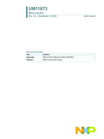
Appendix A - MCU flash-resident bootloader operationChapter 7Appendix A - MCU flash-resident bootloaderoperationThis section describes the linkage between the MCU flash-resident bootloader and the user application. The demonstrationdescribed above illustrates a simple collaboration between the MCU bootloader and the led demo application. Theconsiderations are: The flash-resident bootloader is located in flash at address 0. The user application is located in flash above the bootloader at BL APP VECTOR TABLE ADDRESS The vector table for the User Application is placed at the beginning of the application image. The Bootloader Configuration Area (BCA) is placed at 0x3C0 from the beginning of the image.NOTEThe base address of a user application with a flash-resident bootloader is different than theapplication base address when using a ROM-based bootloader. The application linker file needsto be updated to link the image to the correct base address. In addition, the application vector tablealso needs to be updated based on the correct application location.MCU Bootloader Demo Applications User's Guide, Revision 3, May 201820NXP Semiconductors
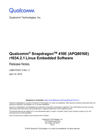
Appendix A - MCU flash-resident bootloader operationMemory map overview7.1 Memory map overviewFigure 16. Device memory mapMCU Bootloader Demo Applications User's Guide, Revision 3, May 2018NXP Semiconductors21
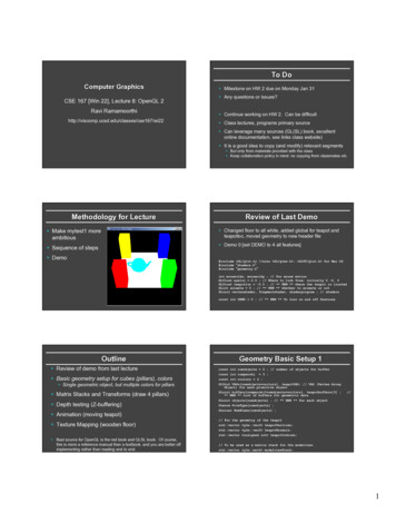
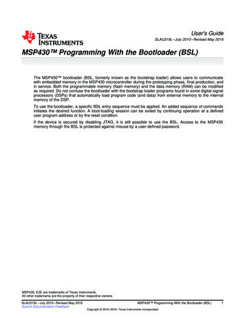
Appendix A - MCU flash-resident bootloader operationUser application vector tableFigure 17. User application vector table and Bootloader Configuration Area (BCA)7.2 User application vector tableThe MCU bootloader checks BL APP VECTOR TABLE ADDRESS 0 for the User Application stack pointer andBL APP VECTOR TABLE ADDRESS 4 for the User Application entry point. Initially, this area is expected to be erased (0xFF)and the bootloader remains in its command interface.After a user application is installed to BL APP VECTOR TABLE ADDRESS, the bootloader jumps to the application after a periodspecified by peripheralDetectionTimeoutMs in the Bootloader Configuration Area (BCA).7.3 Bootloader Configuration Area (BCA)The Bootloader Configuration Area is located at offset 0x3C0 from the beginning of the User Application image. Thisinformation is read by the MCU bootloader early during the bootloader initialization to set up clocks and gather otherinformation relevant to detecting active peripherals. If the first four bytes of the BCA are not ‘kcfg’, the bootloader does notuse any information from the BCA on flash.MCU Bootloader Demo Applications User's Guide, Revision 3, May 201822NXP Semiconductors
Appendix B - MCU Bootloader Development platformsChapter 8Appendix B - MCU Bootloader DevelopmentplatformsAll boards must be in their default factory state for jumper settings.Figure 18. FRDM-K22F platformMCU Bootloader Demo Applications User's Guide, Revision 3, May 2018NXP Semiconductors23
Appendix B - MCU Bootloader Development platformsFigure 19. TWR-K22F120M platformFigure 20. TWR-K24F120M platformMCU Bootloader Demo Applications User's Guide, Revision 3, May 201824NXP Semiconductors
Appendix B - MCU Bootloader Development platformsFigure 21. FRDM-K64F platformFigure 22. TWR-K64F120M platformMCU Bootloader Demo Applications User's Guide, Revision 3, May 2018NXP Semiconductors25
Appendix B - MCU Bootloader Development platformsFigure 23. TWR-K65F180M platformFigure 24. FRDM-K66F platformMCU Bootloader Demo Applications User's Guide, Revision 3, May 201826NXP Semiconductors
Appendix B - MCU Bootloader Development platformsFigure 25. FRDM-KL25Z platformFigure 26. TWR-KV31F120M platformMCU Bootloader Demo Applications User's Guide, Revision 3, May 2018NXP Semiconductors27
Appendix B - MCU Bootloader Development platformsFigure 27. TWR-KV46F150M platformFigure 28. TWR-KV11Z75M platformMCU Bootloader Demo Applications User's Guide, Revision 3, May 201828NXP Semiconductors
Appendix B - MCU Bootloader Development platformsFigure 29. TWR-K80F150M platformFigure 30. FRDM-KL28Z platformMCU Bootloader Demo Applications User's Guide, Revision 3, May 2018NXP Semiconductors29
Appendix B - MCU Bootloader Development platformsFigure 31. FRDM-K82F platformFigure 32. KS22F256 Bootloader MAPS-KS22 platformMCU Bootloader Demo Applications User's Guide, Revision 3, May 201830NXP Semiconductors
Appendix C - MCU Bootloader Pin mappingsChapter 9Appendix C - MCU Bootloader Pin mappingsTable 1. MK22F128R/256R/512R bootloader/flashloader – AltModeTWRK22F120MTest pointsFRDM-K22FTest pointsUART1PTE0UART1 TX3mbed J5PTE1UART1 RXOpenSDA portJ25PTC10I2C1 SCL2J9 pin 1J1 pin 13PTC11I2C1 SDAJ7 pin 1J2 pin 7PTD4SPI1 PCS0J16 pin 1J2 pin 6PTD5SPI1 SCKJ16 pin 3J2 pin 12PTD6SPI1 SOUTJ16 pin 5J2 pin 8PTD7SPI1 SINJ16 pin 7J2 pin 10-USB0 DPUSB J32USB J16I2CSPIUSB11-7DefaultUSB0 DMTable 2. MK24F25612 bootloader – -K24F120MTest pointsUART1PTE0UART1 TX3mbed port J37PTE1UART1 RXPTC10I2C1 SCL2Elev B50PTC11I2C1 SDAPTD4SPI1 PCS0PTD5SPI1 SCKJ3 pin 3PTD6SPI1 SOUTJ3 pin 5PTD7SPI1 SINJ3 pin 7-USB0 DPI2C1SPI1USB-Elev B517DefaultJ3 pin 1USB J23USB0 DMNOTEIf testing the UART interface on mbed port J37, add shunts on J25 pin 2-3. If testing the UARTinterface on TWR-SER, add shunts on J25 pin 1-2 and J22 pin 1-2.MCU Bootloader Demo Applications User's Guide, Revision 3, May 2018NXP Semiconductors31
Appendix C - MCU Bootloader Pin mappingsTable 3. MKL25Z4 bootloader – KL25ZTest pointsUART0PTA2UART0 TX2OpenSDAPTA1UART0 RXPTC8I2C0 SCL2J1 pin 14PTC9I2C0 SDAPTD0SPI0 PCS0PTD1SPI0 SCKJ2 pin 12PTD2SPI0 SOUTJ2 pin 8PTD3SPI0 SINJ2 pin 10-USB0 DPI2CSPIUSB00-J1 pin 162DefaultUSB0 DMJ2 pin 6USB connectorKL25ZTable 4. MK64F12 bootloader – -K64F120MTest pointsUART1PTC4UART1 TX3OpenSDA J2PTC3UART1 RXPTC10I2C1 SCL2Elev A75 or J3 pin3PTC11I2C1 SDAPTD0SPI1 PCS0PTD1SPI1 SCKElev B48PTD2SPI1 SOUTElev B45PTD3SPI1 SINElev B44-USB0 DPI2CSPIUSB10-Elev B71 or J3 pin42DefaultElev B46USB J17USB0 DMTable 5. MK64F12 flashloader – -K64F120MTest pointsUART0PTB17UART0 TX3Elev B11PTB16UART0 RXElev B10Table continues on the next page.MCU Bootloader Demo Applications User's Guide, Revision 3, May 201832NXP Semiconductors
Appendix C - MCU Bootloader Pin mappingsTable 5. MK64F12 flashloader – TWR-K64F120M K64F120MTest pointsI2C1PTC10I2C1 SCL2Elev A75 or J3 pin3PTC11I2C1 SDAPTD0SPI1 PCS0PTD1SPI1 SCKElev B48PTD2SPI1 SOUTElev B45PTD3SPI1 SINElev B44-USB0 DPSPIUSB0-Elev B71 or J3 pin42DefaultElev B46USB J17USB0 DMTable 6. MK64F12 bootloader/flashloader – 64F TestpointsUART0PTB17UART0 TX3mbed port J26PTB16UART0 RXPTC10I2C1 SCL2J4 pin 12PTC11I2C1 SDAPTD0SPI1 PCS0PTD1SPI1 SCKJ2 pin 12PTD2SPI1 SOUTJ2 pin 8PTD3SPI1 SINJ6 pin 10-USB0 DPI2CSPIUSB10-J4 pin 102DefaultJ2 pin 6USB J22USB0 DMTable 7. MK65F18 bootloader – -K65F180MTest pointsUART2PTE16UART2 TX3mbed port J7PTE17UART2 RXPTD8I2C0 SCL2J13 pin 2PTD9I2C0 SDAI2C0J14 pin 1Table continues on the next page.MCU Bootloader Demo Applications User's Guide, Revision 3, May 2018NXP Semiconductors33
Appendix C - MCU Bootloader Pin mappingsTable 7. MK65F18 bootloader – TWR-K65F180M K65F180MTest pointsSPI2PTD11SPI2 PCS02Elev B46PTD12SPI2 SCKElev B48PTD13SPI2 SOUTElev B45PTD14SPI2 SINElev B44-USB0 DPUSB-DefaultTWR SER USBJ14DefaultUSB J15USB0 DMHS USB--USB1 DMUSB1 DPTable 8. MK65F18 flashloader – -K65F180MTest pointsUART4PTE24UART4 TX3Elev A48PTE25UART4 RXPTD8I2C0 SCLPTD9I2C0 SDAPTD11SPI2 PCS0PTD12SPI2 SCKElev B48PTD13SPI2 SOUTElev B45PTD14SPI2 SINElev B44-USB0 DPI2CSPIUSB02-Elev A472J13 pin 2J14 pin 12DefaultUSB0 DMElev B46TWR SER USBJ14Table 9. MK66F18 bootloader – 66F TestpointsUART0PTB17UART0 TX3port J26PTB16UART0 RXPTC10I2C1 SCL2J4 pin 20PTC11I2C1 SDAPTD0SPI1 PCS0PTD1SPI1 SCKI2CSPI10J4 pin 182J2 pin 6J2 pin 12Table continues on the next page.MCU Bootloader Demo Applications User's Guide, Revision 3, May 201834NXP Semiconductors
Appendix C - MCU Bootloader Pin mappingsTable 9. MK66F18 bootloader – FRDM-K66F (continued)PeripheralHS USBInstance-PortSignalAltModePTD2SPI1 SOUTJ2 pin 8PTD3SPI1 SINJ6 pin 10-USB1 DPDefaultFRDM-K66F TestpointsUSB J22USB1 DMTable 10. MK66F18 flashloader – 66F TestpointsUART4PTE24UART4 TX4J2 pin 13PTE25UART4 RXPTC10I2C1 SCLPTC11I2C1 SDAPTD0SPI1 PCS0PTD1SPI1 SCKJ2 pin 12PTD2SPI1 SOUTJ2 pin 8PTD3SPI1 SINJ6 pin 10-USB0 DPI2CSPIUSB10-J2 pin 152J4 pin 20J4 pin 182DefaultJ2 pin 6NAUSB0 DMTable 11. MKV30F12810 bootloader/flashloader – R-KV30F100MTest pointsUART1PTC3UART1 RX3Elev B47PTC4UART1 TXPTB0I2C0 SCLPTB1I2C0 SDAPTE16SPI0 PCS0PTE17SPI0 SCKElev B48PTE18SPI0 SOUTElev B45PTE19SPI0 SINElev B44I2CSPI00Elev A372Elev A30Elev B282Elev B46MCU Bootloader Demo Applications User's Guide, Revision 3, May 2018NXP Semiconductors35
Appendix C - MCU Bootloader Pin mappingsTable 12. MK02F12810 bootloader/flashloader – R-KV30F100MTest pointsUART1PTC3UART1 RX3Elev B47PTC4UART1 TXPTB0I2C0 SCLPTB1I2C0 SDAPTE16SPI0 PCS0PTE17SPI0 SCKElev B48PTE18SPI0 SOUTElev B45PTE19SPI0 SINElev B44I2CSPI00Elev A372Elev A30Elev B282Elev B46Table 13. MKV31F128/256/512 bootloader – R-KV31F120MTest pointsUART0PTB16UART0 TX3OpenSDA portPTB17UART0 RXPTD2I2C0 SCL7J9 pin 2PTD3I2C0 SDAPTE16SPI0 PCS0PTE17SPI0 SCKElev B48PTE18SPI0 SOUTElev B45PTE19SPI0 SINElev B44I2CSPI00J12 pin 12Elev B46Table 14. MKV31F512 bootloader – V31F120MTest pointsUART0PTB17UART0 TX3OpenSDA portPTB16UART0 RXPTB2I2C0 SCL2J2 pin 20PTB1I2C0 SDAPTE16SPI0 PCS0PTE17SPI0 SCKJ2 pin 12PTE18SPI0 SOUTJ2 pin 8PTE19SPI0 SINJ2 pin 10I2CSPI00J2 pin 182J1 pin 15MCU Bootloader Demo Applications User's Guide, Revision 3, May 201836NXP Semiconductors
Appendix C - MCU Bootloader Pin mappingsTable 15. MKV46F15 bootloader – R-KV46F150MTest pointsUART0PTD6UART0 TX3OpenSDA portPTD7UART0 RXPTB0I2C0 SCL2Elev B28 or J501pin 22PTB1I2C0 SDAPTE16SPI0 PCS0PTE17SPI0 SCKElev A28 or J501pin 12PTE18SPI0 SOUTElev B29 or J501pin 18PTE19SPI0 SINElev B30 or J501pin 20PTA12CAN0 TXPTA13CAN0 RXI2C0SPI0FlexCAN0Elev B27 or J501pin 3322Elev A27 or J501pin 10J13 pin 1J13 pin 2Table 16. MKV11Z7 bootloader – -KV11Z75MTest pointsUART0PTD17UART0 TX3OpenSDA J511PTD16UART0 RXPTB0I2C0 SCL2J18 pin 17PTB1I2C0 SDAPTE16SPI0 PCS0PTE17SPI0 SCKJ18 pin 6PTE18SPI0 SOUTJ18 pin 7PTE19SPI0 SINJ18 pin 8PTA24CAN0 TXPTA25CAN0 RXI2C0SPI0FlexCAN0J18 pin 1822J18 pin 5J24 pin 13J24 pin 14NOTEIf testing the UART interface on OpenSDA port J511, add shunts on J505 pin 2-3 and J506 pin 2-3.MCU Bootloader Demo Applications User's Guide, Revision 3, May 2018NXP Semiconductors37
Appendix C - MCU Bootloader Pin mappingsTable 17. MKV11Z7 flashloader – -KV11Z75MTest pointsUART0PTD6UART0 TX3J24 pin 27PTD7UART0 RXPTB0I2C0 SCLPTB1I2C0 SDAPTE16SPI0 PCS0PTE17SPI0 SCKJ18 pin 6PTE18SPI0 SOUTJ18 pin 7PTE19SPI0 SINJ18 pin 8PTA24CAN0 TXPTA25CAN0 RXI2C0SPI0FlexCAN0J24 pin 282J18 pin 17J18 pin 182J18 pin 52J24 pin 13J24 pin 14Table 18. KS22F256 Bootloader - S22F256 Test pointsUART1PTE0UART1 TX3M1-5PTE1UART1 RXPTB0LPI2C0 SCLPTB1LPI2C0 SDAPTD4SPI1 PCS0-PTD5SPI1 SCKCN13-3-PTD6SPI1 SOUTCN13-30-PTD7SPI1 SINCN13-29-USB0 DP-USB0 DMPTB18CAN0 TXPTB19CAN0 RXI2CSPIUSB010FlexCAN-0M1-62OpenSDA porton Dock ANH)MCU Bootloader Demo Applications User's Guide, Revision 3, May 201838NXP Semiconductors
Appendix C - MCU Bootloader Pin mappi
Microsoft Visual Studio Professional 2015 for Windows OS Desktop Microsoft .NET Framework 4.5 (included in Windows OS 8) Microsoft Visual C Redistributable for Visual Studio 2015 (vcredist_x86.exe) Apple Xcode v9.2 (for tools) GNU Compiler (GCC) v5.4.0 (for tools) Overview Toolchain requirement