Transcription
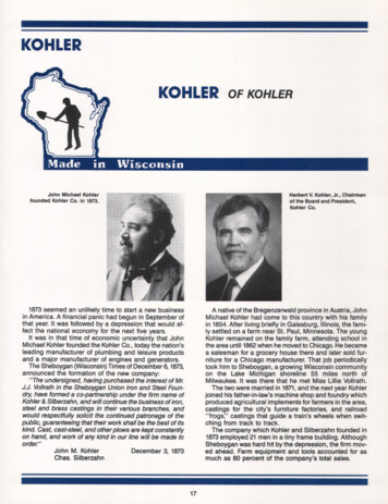
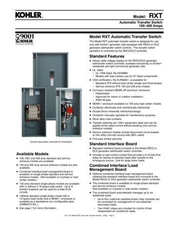
Model:RXTAutomatic Transfer Switch100- 400 AmpsModel RXT Automatic Transfer SwitchThe Model RXT automatic transfer switch is designed for useonly with Kohlerr generator sets equipped with RDC2 or DC2generator set/transfer switch controls. The transfer switchoperation is controlled by the RDC2/DC2 controller.Standard FeaturesD Allows utility voltage display on the RDC2/DC2 generatorset/transfer switch controller, available exclusively on Kohlerrresidential and light commercial generator setsD UL listedd UL 1008 listed, file # E58962d Models with load centers use UL 67 listed componentsD CSA certification, file # LR58301, is available for:d Standard ATS without load center (single and three-phase)d Service entrance ATS 100 and 200 amp modelsD Corrosion-resistant NEMA 3R aluminum enclosured Padlockabled Approved for indoor or outdoor installationd ANSI 49 grayD NEMA 1 enclosure available on 100 amp load center modelsD Contactor electrically and mechanically interlockedD Double throw inherently interlocked designD Contactor manually operable for maintenance purposesD Silver alloy main contactsD Transfer switches are 100% equipment rated and can beapplied at the rated current without derating (non-serviceentrance models)D Service entrance models include disconnect circuit breakeron the utility (normal) source side (80% rated)D Five-year limited warrantyCovers have been removed for illustration.Available ModelsD 100, 200, and 400 amp standard and serviceentrance models are available.D 150 and 300 amp service entrance models are alsoavailable.D Combined interface/ load management board isavailable on single-phase standard and serviceentrance models. (Not available on 3-phase or loadcenter models.)D 100 amp standard single-phase models are availablewith or without a 16-space load center. Up to 8tandem breakers can be used for a total of 24circuits.D 100amp standard single phase model with a12-space load center and a NEMA 1 enclosure isavailable as a standalone non-configurable spec(GM85273-SA ).D See page 7 for more information.Standard Interface BoardD Standard interface board connects to the Model RDC2 orDC2 generator set/transfer switch controller.D Includes a load control contact that provides a 5 minute timedelay for startup of selected loads after transfer to theemergency source. Use for large motor loads.Combined Interface/ LoadManagement BoardD Optional combined interface/ load management boardreplaces the standard interface board and connects to theModel RDC2 or DC2 generator set/transfer switch controller.D The combined board is available on single-phase standardand service entrance models.(Not available on 3-phase or load center models.)D The combined board automatically manages up to sixresidential loads:d Up to four customer-supplied power relay modules canbe connected for management of non-essentialsecondary loads.d Two HVAC relays are included for control of twoindependent air conditioner loads.G11-140 (Model RXT Automatic Transfer Switch) 3/20gPage 1
SpecificationsCodes and StandardsThe ATS meets or exceeds the requirements of the followingspecifications:Standard Interface BoardController interface connectionsA and BController interface connectionsPWR and COMLoad control contact ratingLoad control connections#20 AWG shielded twisted-pairBelden 9402 or 8762 or equivalent#12- 20 AWG(see ATS Installation Manual)10 A @ 250 VAC#12- 18 AWGNote: For combined interface/ load management boardspecifications, see page 3.Environmental SpecificationsOperating temperature Storage temperature Humidity20 C to 70 C ( 4 F to 158 F)40 C to 85 C ( 40 F to 185 F)5 to 95% noncondensingD Underwriters Laboratories UL 1008, Standard for AutomaticTransfer Switches for Use in Emergency Systems, file# E58962D Underwriters Laboratories UL 508, Standard for IndustrialControl EquipmentD CSA certification available, file # LR58301 (not available for150, 300, or 400 amp service entrance or 100 amp loadcenter models). Must be selected when the transfer switchis ordered.D NFPA 70, National Electrical CodeD NFPA 110, Emergency and Standby Power SystemsD NEMA Standard IC10- 1993, AC Automatic TransferSwitchesCable SizesAL/CU UL-Listed Solderless Screw-Type Terminals for External Power ge of Wire Sizes, Cu/AlSwitchPhasesNormal and EmergencyLoadNeutralStandard1(1) #14 - 1/0 AWG(1) #14 – 1/0 AWG(5) #12 to 250 KCMIL (Cu) or(5) #10 to 250 KCMIL (Al)12- or 16space loadcenter(NEMA 1)1(1) #14 – 1/0 AWGper customer-suppliedcircuit breaker(26) #4 - 14 AWG or(2) #14 - 1/0 AWG or(1) #6 – 2/0 AWG16-spaceload center(NEMA 3R)1(1) #14 – 1/0 AWGper customer-suppliedcircuit breaker(26) #4 - 14 AWG or(2) #14 - 1/0 AWG or(1) 2/0 AWGServiceEntrance1Normal: (1) #12 – 2/0 AWGEmerg: (1) #14 – 1/0 AWG(1) #14 – 1/0 AWG(5) #12 to 250 KCMIL (Cu) or(5) #10 to 250 KCMIL (Al)3-Phase3(1) #14 – 1/0 AWG(1) #14 – 1/0 AWG(3) #4 AWG – 600 KCMIL(6) 1/0 AWG – 250 KCMILServiceEntrance1Normal: (1) #4 – 300 KCMILEmerg: (1) #6 - 250 KCMIL(1) #6 – 250 KCMIL(5) #12 to 250 KCMIL (Cu) or(5) #10 to 250 KCMIL (Al)Standard13-Phase3(1) #6 AWG – 250 KCMIL(1) #6 – 250 KCMIL(5) #12 to 250 KCMIL (Cu) or(5) #10 to 250 KCMIL (Al)(9) #14 – #4 AWG(4) #14 - 1/0 AWGServiceEntrance1Normal: : (1) #1 - 600 KCMILor (2) #1 – 250 KCMILEmerg: (2) #6 - 250 KCMIL(2) #6 – 250 KCMIL(3) #4 AWG – 600 KCMIL(6) 1/0 AWG – 250 KCMIL(6) #6 – 3/0 AWGStandard13-pole208-240 V3(2) #6 – 250 KCMIL(2) #6 – 250 KCMIL(6) #6 – 3/0 AWG3 or 4 pole480 V(3) #4 AWG – 600 KCMIL(6) 1/0 AWG – 250 KCMIL3(1) #4 – 600 KCMIL(2) 1/0 – 250 KCMIL(1) #4 – 600 KCMIL(2) 1/0 – 250 KCMILGround(9) #6 – #14 AWG(4) #14 - 1/0 AWG(4) #14 – 1/0 AWG(9) #14 - #6 AWGNote: Data is subject to change. Refer to the transfer switch dimension drawings and wiring diagrams for planning and installation.G11-140 (Model RXT Automatic Transfer Switch) 3/20gPage 2
Optional Combined Interface/Load Management BoardThe RXT transfer switch is available with either a standardinterface board or a combined interface/ load managementboard. The combined board allows load management asdescribed below.Load ManagementD The combined load management board disconnectsnon-critical loads to prevent generator overload, incompliance with NEC.D The combined load management board monitors generatorcurrent and frequency to determine when to add or shedloads. This monitoring prevents frequency drops that candamage valuable electronics like computers and televisions.D Load management allows the use of a smaller generator set.OperationD Loads are automatically added or shed based on generatorcapacity.D The load control system uses dynamic logic to preventshedding important loads unnecessarily when airconditioning, refrigerator, or water pump motors start(patent pending).D The load management board and generator communicate toprovide smart power management. The time to shed loadsdecreases as each load is shed to quickly adapt to criticalpower requirements.D Load shed power level and frequency setpoints can beadjusted using a personal computer (laptop) and KohlerrSiteTecht software, which is only available to Kohlerauthorized distributors and dealers.Priority SettingD Loads are added and shed according to their priority. Load 1is the top priority, which is added first and shed last. Load 6is the lowest priority.D Less critical loads can be turned off automatically whenessential appliances are running.D Load priorities are hard-wired at installation.Viewing Load Shed Outputs with OnCuerPlusD Use Kohler’s OnCuer Plus Generator Management System(sold separately) to view load status (On or Off) for loadsconnected to the load shed relays.D Use OnCuer Plus to remotely monitor when loads are shedor added.D The load shed outputs can be labeled in OnCuer Plus.Current TransformerD The combined load management board option includes a400 amp current transfomer (CT) for load monitoring.D A larger diameter CT is available for applications that requirelarger cables.D A 500 amp CT is available for use with a 60RCL generator.D See the table below for current transformer specificationsand optional kit numbers.Load Shed SpecificationsConnectionRatingConnectionPilot Relays*125VAC, 10 A total (general purpose)120VAC, 125VA (pilot duty)#12- 20 AWGHVAC Relays (qty. 2)125VAC, 10 A (general purpose)120VAC, 125VA (pilot duty)#12- 20 AWGRBUS Communication and PowerConnections to the RDC2/DC2controller0.5 A @ 12 VDCUse Belden #9402 or equivalent 20 AWGshielded, twisted-pair communicationscable [* Four (4) pilot relays are provided for customer-supplied normally closed load-switching contactors/relays. The combination of four load relayoutputs cannot exceed 10 amps total current draw. Kohlerr power relay modules are recommended.[ For long distances, use an equivalent shielded, twisted-pair cable for RBUS connections and individual 12- 20 AWG wires (qty. 2) for powerconnections.Current Transformer SpecificationsRatio(Amps:VAC)Outer Diametermm (in.)Inner Diametermm (in.)Service PartNumberSales Kit Part NumberCT Availability400:363.5 (2.5)28.7 (1.13)GM83929N/AIncluded with combinedboard400:3111.8 (4.4)57.2 (2.25)GM17250GM17250-KP1-QSSold Separately500:3171.5 (6.75)108.0 (4.25)GM60264GM17250-KP2-QSSold Separately(use with 60RCL)G11-140 (Model RXT Automatic Transfer Switch) 3/20gPage 3
Withstand and Close-On Ratings (WCR)Service Entrance Transfer Switch RatingsThe service entrance transfer switch is factory-equipped with a normal source disconnect circuit breaker.Suitable for the control of motors, electric discharge lamps, tungsten filament lamps and electric heating equipment where the sumof motor full-load ampere ratings and the ampere ratings of other loads do not exceed the ampere rating of the switch and thetungsten load does not exceed 30 percent of switch rating.Switch Rating, Amps *WCR, RMS Symmetrical Amps at 240 VAC100, 150, 20022,000300, 40035,000* Continuous load current not to exceed 80% of switch rating.Contactor Ratings with Coordinated Circuit BreakersSingle-phase transfer switches are UL listed at 240 VAC maximum. Three-phase transfer switches are rated at 480 VACmaximum. The following table lists contactor withstand current ratings (WCR) for 100- 400 ampere non-service entrance ratedswitches with specific manufacturer’s circuit breakers per UL and Canadian safety standards. Suitable for the control of motors,electric discharge lamps, tungsten filament lamps and electric heating equipment where the sum of motor full-load ampere ratingsand the ampere ratings of other loads do not exceed the ampere rating of the switch and the tungsten load does not exceed 30percent of switch rating.The transfer switch is rated for use on a circuit capable of delivering not more than the RMS symmetrical amperes maximum asshown in the tables below, but no greater than the interrupting capacity of the selected breaker.WCR Ratings with Specific Manufacturer’s Molded-Case Circuit BreakersSwitchRating,AmpsNumberof Poles/PhasesVoltage,max.WCR, RMSSymmetricalAmpsManufacturer1002402 pole/1 phase10,000Any Breaker *Any Breaker (0.025 seconds max.)—1502002402 pole/1 phase10,000Any Breaker *Any Breaker (0.025 seconds max.)—Eaton1002003 pole/3 phase480ITE/Siemens30,0004 pole/3 phaseGeneral ElectricSchneiderType or ClassMaximumSize, AmpsFCL100JGS, JGH, JGC, JGU, JGX, JBD, JD, HJD, JDC,LCL, LCLA250LDC, CLDC, KDB, KD, HKD, KDC, LD, CLD,HLD, CHLD400CED6, HED4, HED6125CFD6, FD6A, FXD6, HFD6, HFXD6, HHFD6,HHFXD6250CJD6400SEL, SEP, THLC1, PE E, PE N, PE H, PE L150THLC2225SFH, SFL, SFP, PE E, PE N, PE H, PE L250SGH, SGL, SGP, FGN, FGH, FGL, FGP, PG E,PG N, PG H, PG L, PG P400HG, HJ, HL, HR150JJ, JL, JR250LG, LJ, LL, LR400* For higher WCR values, contact the factory for additional specific breaker ratings.G11-140 (Model RXT Automatic Transfer Switch) 3/20gPage 4
WCR Ratings with Specific Manufacturer’s Molded-Case Circuit BreakersSwitchRating,AmpsVoltage,max.Numberof Poles/PhasesWCR, RMSSymmetricalAmpsManufacturerABBEatonGeneral Electric3004002402 pole/1 phase35,000SiemensSquare DMerlin GerinSchneider2403 pole/3 phase4 pole/3 phase65,000General ElectricEaton400ITE/Siemens4803 pole/3 phase50,0004 pole/3 phaseGeneral ElectricSchneider100,000General ElectricType or ClassMaximumSize, AmpsT5, T6600CHKD, CKD, DK, HKD, KD, KDB, KDC,LA TRIPAC, LCL400CHLD, CLD, CLDC, HLD, LD, LDB, LDC600HMDL, MDL, NB TRI- PAC800FGH, FGL, FGN, FGP, SGHA600CJD6, HHJD6, HHJXD6, HJD6, HJGA, HJXD6,JD6, JXD2, JXD6, SCJD6, SHJD6, SJD6, NJGA,LJGA400CLD, HHLD, HHLXD, HLD, HLGA, HLXD, LD,LLGA, LXD, NLGA, SCLD, SHLD, SLD600CMD, HLMD, HLMXD, HMD, HMG, HMXD, LMD,LMG, LMXD, MD, MXD, NMG, SCMD, SHMD,SMD800LA, LC, LE, LH, LI, LX, LXI400DG, DJ, DL, LC, LE, LI, LX, LXI600CJ400H, CJ400L, CJ400N400CJ600H, CJ600N600LJ, LL, LR600SEL, SEP, PE N, PE H, PE L150SFL, SFP, PE N, PE H, PE L250SGL, SGP400SGL, SGP, FGL, FGP600HJD, JDC, JGC, JGH, JGU, JGX250CHLD4, CLD, HLD4, CLDC, LDC, KDC, HKD,CHMDL4, CMDL4400CHLD6, HDL6, CHMDL6, CMDL6, CLDC, CLD6,LDC6, CLDC6600CHMDL8, HMDL8, MDL8, CMDL8800CFD6, HFD6, HFXD6, HHFD6, HHFXD6250CJD6400CLD6, HHLD6, HHLXD6, HLD6, HLXD6600CMD6, MD6, HMD6, HMXD6, MXD6800SEL, SEP, PE N, PE H, PE L150SFL, SFP, PE N, PE H, PE L250SGL, SGP400FGL, FGP, SGL, SGP, PG H, PG L, PG N,PG P600HJ, HL, HR150JJ, JL, JR250LJ, LL, LR600MJ800PG H, PG L, PG P600G11-140 (Model RXT Automatic Transfer Switch) 3/20gPage 5
Dimensions and WeightsNote: Always use the transfer switch dimension drawing for planning and installation. Weights and dimensions may vary fordifferent configurations. See the Operation/Installation Manual or your local distributor for dimension drawings.Transfer switch weights and dimensions shown in the table do not include packaging. To estimate the shipping weight, add 3 kg(5 lbs.) or 10% (whichever is larger) to the weight shown.HWD*ShippingWeight ]kgSingle phaseDimensions, H x W x D, mm (in.) [623 x 335 x 180(24.5 x 13.2 x 7.1)7(15)DimensionDrawingADV-8688With 12-space load center (NEMA 1)610 x 330 x 154(24.0 x 13.0 x 6.0)12(26)ADV-9186With 16-space load center (NEMA 1)610 x 330 x 154(24.0 x 13.0 x 6.0)12(26)ADV-9187With 16-space load center614 x 335 x 180(24.2 x 13.2 x 7.1)8(18)ADV-9188Three phase682 x 462 x 228(26.8 x 18.2 x 9.0)14(30)ADV-8689Service entrance (ASE)734 x 416 x 175(28.9 x 16.4 x 6.9)10(22)ADV-9046Service entrance (CSE)754 x 416 x 175(29.7 x 16.4 x 6.9)14(30)ADV-8797Service entrance (ASE)734 x 416 x 175(28.9 x 16.4 x 6.9)12(26)ADV-9046Service entrance (ASE)734 x 416 x 175(28.9 x 16.4 x 6.9)12(26)ADV-9046Service entrance (CSE)754 x 416 x 175(29.7 x 16.4 x 6.9)16(36)ADV-8798Single phase623 x 335 x 180(24.5 x 13.2 x 7.1)7(15)ADV-8688Three phase682 x 462 x 228(26.8 x 18.2 x 9.0)14(30)ADV-8689Service entrance1075 x 559 x 329(42.3 x 22.0 x 12.9)46 (101)ADV-8694Single phase1067 x 559 x 329(42.0 x 22.0 x 12.9)55 (120)ADV-86913-Pole/208- 240 volts1067 x 559 x 329(42.0 x 22.0 x 12.9)41(90)ADV-86923-Pole/480 volts1222 x 610 x 343(48.1 x 24.0 x 13.5)59 (130)ADV-86934-Pole1222 x 610 x 343(48.1 x 24.0 x 13.5)59 (130)ADV-8693Service entrance1075 x 559 x 329(42.3 x 22.0 x 12.9)46 (101)ADV-8694Amps100150200300400Description[ Depth does not include the padlock hasp on the front of the enclosure.] Transfer switch weights are approximate and do not include packaging.Note:Enclosures are type NEMA 3R except as noted.G11-140 (Model RXT Automatic Transfer Switch) 3/20gPage 6(lb.)
Accessories- Auxiliary position-indicating contactsD One closed on normal position and one closed on emergencypositionD Form C contacts rated 15 A @ 250 VAC- Power relay modulesD 50 amp DPST power relay mounted in a NEMA type 3RenclosureD Use up to four modules with the combined interface/ loadmanagement boardD UL/cUL listedD Dimensions: 172 x 233 x 92 mm (6.8 x 9.2 x 3.6 in.)D For more information, see specification sheet G6-143- Status indicator kit for standard interface boardD LEDs indicate normal and emergency source availabilityand contactor positionD Mounts on the outside of the RXT enclosureD View transfer switch status without removing enclosurecoverD An overhang on the enclosure protects the indicatorpanel and ribbon cable openingD Dimensions: 92 mm x 42 mm (3.62 in. x 1.65 in.)D Connects to the standard interface board onlyD For more information on the status indicator kit, seespecification sheet G11-123- Status indicator kit for combined interface/ loadmanagement boardD LEDs indicate normal and emergency source availabilityand contactor positionD Dual color LEDs for each load indicate load status(powered or shed) and flash during a testD Load shed test button allows the operator to cycle theload shed relays in order of priority (when generator is inRUN mode)D Mounts on the outside of the RXT enclosureD View transfer switch and load status without removingenclosure coverD An overhang on the enclosure protects the indicatorpanel and ribbon cable openingD Dimensions: 183 mm x 42 mm (7.20 in. x 1.65 in.)D Connects to the combined interface/ load managementboard onlyD For more information on the status indicator kit, seespecification sheet G11-123- Auxiliary circuit breaker (service entrance models only)D 15 amp single-pole type QO circuit breakerD Mounts on a bracket inside the enclosureAvailable ModelsAll Model RXT transfer switches are standard-transition 60 Hz automatic transfer switches. Letters in parentheses refer to themodel designation code described on the last page.Amps100Description(Connections)Voltages208 (C)240 (F)480 (M)PolesPhasesWCR wRMS Symmetrical AmpsStandard (A)D2 (N)110,000Standard, with 16-space loadcenter (B) WD2 (N)110,000Standard, with 12-spaceload center **D2 (N)110,000Service entrance (ASE, CSE)Standard, 3-phase (A)2 (N)122,0003 (T) or 4 (V)330,000DDDD150Service entrance (ASE)D2 (N)122,000Standard (A)D2 (N)110,000200Service entrance (ASE, CSE)D2 (N)122,0003 (T) or 4 (V)330,000Standard, 3-phase (A)300400DDDService entrance (ASE)D2 (N)135,000Standard (A)D2 (N)150,000Service entrance (ASE)D2 (N)135,0003 (T) or 4 (V)350,000Standard, 3-phase (A)DDDw Withstand and close-on rating. See pages 3-5 for WCR information and specific breaker ratings.W With 16-space load center and NEMA 1 or NEMA 3R enclosure. Up to 8 tandem breakers can be used, for a maximum of 24 circuits.** GM85273- SA with 12-space load center and NEMA 1 enclosure.Note:Combined interface board is available on single-phase standard or service entrance models. (Not available on 3-phase or load center models.)G11-140 (Model RXT Automatic Transfer Switch) 3/20gPage 7
KOHLER CO., Kohler, Wisconsin 53044 USAPhone 920-457-4441, Fax 920-459-1646For the nearest sales and service outlet in theUS and Canada, phone 1-800-544-2444KOHLERPower.comModel nt RatingConnectionsRecord the transfer switch model designation in the boxes. The transfer switch model designation defines ratings andcharacteristics as explained below.Sample Model Designation:ModelRXT: Kohler Automatic Transfer SwitchControlsJ:Interface for RDC2/DC2 Controller(standard or combined interface/ loadmanagement)Voltage/FrequencyC:208 Volts/60 Hz (3-phase only)F:240 Volts/60 HzM:480 Volts/60 Hz (3-phase only)Number of Poles/WiresN:2-pole, 3-wire, solid neutral (120/240 V only)T:3-pole, 4-wire, solid neutralV:4-pole, 4-wire, switched neutralRXT-JFNC-0200AEnclosureA:NEMA 1 *C:NEMA 3R* NEMA 1 enclosure is available on 100 amp load center models only.Current Rating0100: 100 amps0150: 150 amps0200: 200 amps0300: 300 amps0400: 400 ampsConnectionsA:No load centerB:With load center (100 amp single-phase only)ASE: Service entrance ratedCSE: Service entrance rated with CSA certification(100/200 amps only)DISTRIBUTED BY:Availability is subject to change without notice. Kohler Co. reserves theright to change the design or specifications without notice and withoutany obligation or liability whatsoever. Contact your local Kohlerrgenerator distributor for availability. 2014 Kohler Co. All rights reserved.G11-140 (Model RXT Automatic Transfer Switch) 3/20gPage 8
Pilot Relays* 125VAC, 10 A total (general purpose) 120VAC, 125VA (pilot duty) #12-20 AWG HVAC Relays (qty. 2) 125VAC, 10 A (general purpose) 120VAC, 125VA (pilot duty) #12-20 AWG RBUS Communication and Power Connections to the RDC2/DC2 controller 0.5A @ 12 VDC Use Belden #9402 or equivalent 20 AWG shielded, twisted-pair communications cable