Transcription
OWNER'S MANUALENVCMX CONDENSATE PUMP SERIESEnglishThis pump automatically removes condensate water that drips from an air conditioner evaporator coil,refrigeration equipment coil, condensing furnace, or condensing boiler. The pump is controlled by a floatswitch mechanism, which automatically starts and stopsthe pump.Some models also include a high-water level switch, whichopens a thermostat circuit when the pump reservoir is full,stopping production of condensate. Alternatively, thisswitch can be reconfigured to close a circuit, which canoperate an external alarm or relay, (purchased separately).This product is covered by a Limited Warranty for a periodof 36 months from the date of original purchase by theconsumer. For complete warranty information, refer to WattsShut OffVCMX-20 SeriesVCMX-20 Series1152306050/601.50.7/0.6937521’ (6.4 m)20’ (6.1 m)SAFETY INSTRUCTIONSBefore Getting StartedThis equipment should be installed and serviced by technically qualified personnel who are familiar withthe correct selection and use of appropriate tools, equipment, and procedures. Failure to comply withnational and local electrical and plumbing codes and within Little Giant recommendations may result inelectrical shock or fire hazard, unsatisfactory performance, or equipment failure.Know the product’s application, limitations, and potential hazards. Read and follow instructions carefully toavoid injury and property damage. Do not disassemble or repair unit unless described in this manual.Failure to follow installation or operation procedures and all applicable codes may result in the followinghazards:Risk of death, personal injury, or property damage due to explosion,fire, or electric shock. Do not use to pump flammable or explosive fluids such as gasoline, fuel oil, kerosene, etc.Do not use in explosive atmospheres or hazardous locations as classified by the NEC, ANSI/NFPA70.Do not handle a pump or pump motor with wet hands or when standing on a wet or damp surface, or in water.When a pump is in its application, do not touch the motor, pipes, or water until the unit is unplugged or electrically disconnected. If the power disconnect is out of sight, lock it in the open position and tag it to prevent unexpected application ofpower.
SAFETY INSTRUCTIONSBefore Getting StartedRisk of severe injury or death by electrical shock. To reduce risk of electrical shock, disconnect power before working on or around the system.Wire pump system for correct voltage.Be certain that this pump is connected to a circuit equipped with a ground fault circuit interrupter (GFCI) device if required bycode.Check electrical outlets with a circuit analyzer to ensure power, neutral, and ground wires are properly connected.Some pumps are supplied with a grounding conductor and grounding-type attachment plug. To reduce risk of electric shock, becertain that it is connected only to a properly grounded grounding-type receptacle. Do not remove the third prong from the plug.The third prong is to ground the pump to help prevent possible electric shock hazard.Some pumps are supplied with lead wires and are intended to be hardwired using a junction box or other approved enclosure.The pumps include a grounding connector. To reduce risk of electric shock, be certain that it is properly connected to ground.In a 230 V direct wire installation, one side of the line going to the pump is always electrically energized, regardless of whetherthe liquid level control switch is open or closed. To avoid hazards when installing or servicing, install a double-pole disconnectnear the pump installation.The flexible jacketed cord assembly mounted to the pump must not be modified in any way, with the exception of shortening thecord to fit into a control panel. Any splice between the pump and the control panel must be made within a junction box and comply with the National Electrical Code.Check local electrical and building codes before installation. The installation must be in accordance with their regulations as wellas the most recent National Electrical Code (NEC) and the Occupational Safety and Health Act (OSHA).Do not use the power cord for lifting the pump.Do not use an extension cord.The pump should only be used with liquids compatible with pump component materials. If the pump is used with liquids incompatible with the pump components, the liquid can cause failure to the electrical insulation system resulting in electrical shock.Risk of bodily injury, electric shock, or equipment damage. This equipment must not be used by children or persons with reduced physical, sensory or mental abilities, or lacking in experience and expertise, unless supervised or instructed. Children may not use the equipment, nor may they play with the unit or inthe immediate vicinity.Equipment can start automatically. Lockout-Tagout before servicing equipment.An inoperative or malfunctioning pump could lead to flooding, resulting in personal injury or property damage.Operation of this equipment requires detailed installation and operation instructions provided in this manual. Read entire manualbefore starting installation and operation. End User should receive and retain manual for future use.Risk of damage to pump or other equipment. 2Before installing pump, allow air conditioner to cycle several times, collecting condensate in a separate container to help flush anyresidual oils that may remain in the system. Failure to flush the system can result in damage to the pump and drain line plumbingcomponents.When operating in a gas furnace environment, care must be taken to ensure acidity of condensate does not fall below the averagepH of 3.4 (to prevent a localized pocket of acid that acts like a battery causing pitting) by routinely cleaning or flushing tank withfresh water.Support pump and piping when assembling and when installed. Failure to do so may cause piping to break, pump to fail, motorbearing failures, etc.Do not install the pump in a manner that will subject it to splashing or spraying.Periodically inspect pump and system components. Regularly check hoses for weakness or wear, making certain that all connections are secure.Schedule and perform routine maintenance as required and in accordance with the Maintenance section of this manual.Pump is for indoor use only.Do not use this pump inside an air plenum.
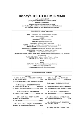
INSTALLATIONPhysical InstallationINSTALLATIONPhysical InstallationBracketEnsure bracket is levelWall1. Install the pump on a flat surfaceScrews Install the enclosed rubber feet onto thebottom of the tank.Bracket Make sure the mounting surface will supAnti-sweat sleeveport the weight of the pump and waterfilled tank.2. The pump can also be mounted onto a wall orthe side of an air conditioner or furnace, usingBracketthe enclosed mounting bracket. The tank hasScrewsamounting slot on each side so it can be positioned either way.3. Pumps with an anti-sweat sleeve use a different bracket, but the mounting location holes are thesame and the brackets are interchangeable.4. Ensure that the pump is level and the inlet is below the coil drain.Piping Connections61. Cut end of pipe(s) from2evaporator or furnace drainat a 45 angle as shown to3prevent pipe(s) from sealing21closed when sitting against52the tank’s floor.42. The pump will accept up tothree drain lines. However,take care to make sure that total inflow does not exceed the rated output of the pump to preventoverflow. Route drain pipe(s) downward into one or more pump inlet openings one to three inches,ensuring no interference with float operation. Keep any unused openings closed using the suppliedcap plugs.3. Install outlet tubing or piping onto outlet check valve and secure with hose clamp (not provided). Use 3/8” inside diameter maximum tubing or piping to prevent excessive flow back to unit.4. Route outlet tubing or piping from pump straight up as high as necessary. Do not extend higher than 75% of the total dynamic head capacity of the pump.5. From the high point, slope discharge line down slightly to a point above the drain area. Then, turndown and route to a suitable drain at a point below or approximately level with the bottom of thepump, if possible. This will produce a siphoning effect which will improve efficiency of the pump.6. If it is not possible to slope the discharge line down, make an inverted “U” trap directly above thepump at the highest point.Electrical ConnectionsConnect the power cord to a constant source of power matching the pump nameplate voltage. The pump should be connected or wired to its own circuit, with no other electric receptacles orequipment in the circuit. Do not connect to a fan or any device that runs intermittently. The fuses or circuit breaker should be of ample capacity. Connect to a circuit equipped with a ground fault circuit interrupter (GFCI) if required by code.Some models are supplied with a stripped wire cord end. Power connections must be made within ajunction box, and must comply with the National Electrical Code. Wires are color coded as follows: Green/yellow Ground; Brown Line; Blue Line (230 V) or Neutral (115 V)IMPORTANT: If the power cord is damaged, the whole unit must be replaced.3
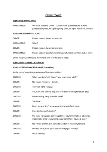
INSTALLATIONElectrical ConnectionsHigh Water Level Switch ConnectionRisk of bodily injury or property damage. In applications where property damage and/or personal injury might result from an inoperative or leaking pump due to poweroutages, discharge line blockage, or any other reason, a backup system(s) (e.g. auxiliary switch) and/or alarm should be usedand monitored.The high level switch should be connected to a Class II Low Voltage circuit. The two switch wires are black. Do not confuse thesewires with the line voltage power conductors.The high level switch is placed in an orientation that reverses the normal function of normally open and normally closed terminals. Pay close attention to the following k379Black 2N63141. High Water Level Switch2. NO terminal. Connect here to shut off the condensing unit of the heating/cooling system.3. NC terminal. Connect here to activate an external alarm or relay.4. High Water Level Switch wiring leads5. Switch housing tabs6. Hinge tab7. Switch Mounting Ribs. When installing switch, make sure it is positioned between these ribs.8. Thermostat9. Air Conditioner/FurnaceThere are two options for connecting the high level switch:1. The switch is factory wired to the NO and COM terminals. This configuration will open (break) anelectrical circuit when the switch is activated by a high water level in the reservoir, which can beused to stop the condensing unit(s) of the heating/cooling system. Refer to the thermostat and heating/cooling unit’s Operating Manual for expected switch operation and wiring connections. Connect the switch leads (4) in series with the low voltage thermostat circuit as specified in the heating/cooling unit’s operating manual.2. The installer can reconfigure this switch to the NC terminal to close a low voltage circuit in the eventof high water level, which could activate an external alarm or relay (purchased separately). Use thefollowing procedure if an NC configuration is required: Squeeze the High Level Switch housing tabs at (5). Rotate the housing upwards at hinge tab (6); or, remove the housing completely by lifting thehousing hinge tab out of the slot. Support the switch and carefully change the lead wire from the NO terminal to the NC terminal(3). Return the Switch housing back to the switch base. Squeeze the tabs together at (5) and insert into the switch base between ribs (7). Connect the switch leads in series with the low voltage external component as specified in thecomponent’s manual.Place the “Attention Service Technician” label included with the pump on the outside of the accesspanel in a visible location.4
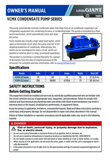
MAINTENANCEOperation TestingOperation Testing1. Turn on power to the pump.2. Test pump operating switch by pressing lightly on the external test/runlever to start the motor.3. Test high level switch by raising highlevel switch float. If wired to NO terminal, airhandling device should shut down when float is raised. If wired to NC terminal, external component (alarm or relay) should activate when float is raised.MAINTENANCERisk of bodily injury or property damage. Do not allow the tank to overflow during this maintenance.Inspect and test the condensate removal system condition and operation every 6 months (more frequently in heavy-use applications).1. Disconnect the pump from the power source.2. Remove the ¼ turn check valve.Inspect the check valve and cleanLift coverwith warm water and mild soap ifnecessary.3. Remove tank assembly from thepump by squeezing the reservoir atplaces indicated to release thelatch. Place a finger in one of thelarger holes in the corner of theSqueezetop and lift to remove the topHinge endpart of the pump. The tophinges on the opposite end ofSqueezethe tank.4. Be sure the floats move freely. Clean as necessary.5. Clean the tank with warm water and mild soap.6. Flush tank with fresh water. This helps to ensure that residual condensate does not create localizedpockets of acid that could cause pitting.7. Check inlet and outlet piping. Clean as necessary. Be sure there are no kinks in the line that wouldinhibit flow.8. Replace the tank assembly to the pump.9. Replace inlet and outlet piping. Fully insert the check valve into the discharge line,ensuring that the O-ring and discharge line are freeof debris. Insert the check valve into the pump discharge holeand twist it by hand ¼ turn. Check to ensure that the check valve is securelylocked into position.10. Test operation of the system.5
mp does not startwhen tank is full ofcondensate water.Condensate is overflowing from the tank.Pump will not shut off.Pump runs but
Do not handle a pump or pump motor with wet hands or when standing on a wet or damp surface, or in water. When a pump is in its application, do not touch the motor, pipes, or water until the unit is unplugged or electri- cally disconnected. If the power disconnect is out of sight, lock it in the open position and tag it to prevent unexpected application of power. SAFETY .