Transcription
Lab View with cRIO TutorialControl System DesignFeb. 14, 2006
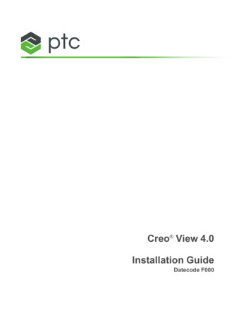
Experimental Set upPower SuppliesPan and Tilt MechanismrneehEtlebatccRIO ReconfigurableEmbedded SystemLab View Additional SoftwareAmplifiers
Control Hardware NI recommends configuring a private network between the cRIO and thehost system (student laptops):IP: 192.168.0.2IP: 192.168.0.3IP: 192.168.0.2IP: 192.168.0.3IP: 192.168.0.2IP: 192.168.0.3Student Laptops
Configuring the Network1. cRIO network settings already configured: IP address: 192 . 168 . 0 . 2 Subnet mask: 255 . 255 . 0 . 02. Network settings of the host system (student laptops):1. Open Network Connections (accessible through Control Panel)2. Right-click the appropriate Local Area Connection and select Properties. On the Generaltab, under This connection uses the following items, click Internet Protocol (TCP/IP),and then click Properties.
Configuring the Network (cont’d)3. To specify an IP address click Use the following IP address, and enter the following IPaddress and subnet mask.4. Click OK.5. Click Close.
cRIO and Host Computer Operation1. cRIO starts a LabVIEW Real-Time Module executable when powered on. The executablecontains the LabVIEW FPGA Module code.2. The LabVIEW Real-Time Module executable waits for an incoming TCP/IP connectionfrom the host in order to pass control messages.3. The cRIO establishes a second TCP/IP connection for transferring data back to the hostwhen the host initiates an acquisition.4. The USER1 LED remains lit until the acquisition finishes or an error occurs afterestablishing a connection with a host system.
cRIO and Host Computer Operation (Cont’d)Complete PAC Architecture Using LabVIEW FPGA, LabVIEW Real-Time and Host PC
Developing an FPGA Application1. Launch LabVIEW.2. Select the FPGA device that is connected to the CompactRIO R Series Expansionchassis from the Execution Target pull-down menu in the LabVIEW window.3. LabVIEW automatically launches the Embedded Project Manager window. In theEmbedded Project Manager window, select File»New. The New dialog box appears.4. On the Projects tab, enter the name of your project in the Project name text box.5. Click the Browse button. The Select project directory dialog box appears.6. Browse to the directory where you want to save the LEP file. Click the Select Cur Dirbutton. The directory path appears in the Project location listbox.7. Click the OK button.
Developing an FPGA Application (Cont’d)Configuring a cRIO Expansion System in Software:8. In the Embedded Project Manager window, select Hardware»Configure Target forCompactRIO. The Configure Target for CompactRIO dialog box appears.9. Click Discover Modules to auto-detect all modules installed in the chassis.10. Click OK.11. Select File»Save Project in the Embedded Project Manager window. LabVIEW savesthe configuration settings in the LEP file.
Developing an FPGA Application (Cont’d)Develop a FPGA VI: In the Embedded Project Manager window, select Project»Add to Project»New. TheNew dialog box appears.Select Blank VI in the left pane. Enter the name of the file to be implemented in theFPGA in the Filename text box. Verify that the Add to active project checkbox isselected. Click the OK button. The blank VI appears.
Developing an FPGA Application (Cont’d)2 PIDs for the pan and tilt mechanism:Build the FPGA application shown below in Figure 1. For detailed instructions,refer to the instructions below: Place 3 While Loops on the block diagram. Right-click the conditional terminal for thethree of them and select Create»Control from the shortcut menu.Place an Digital Input function in the lower left While Loop. The Digital Input function ison the FPGA Device I/O palette.Double-click the function. The Configure Digital Input dialog box appears.Select Slot4/cRIO-9411/DI 0 from the Terminal pull-down menu.Click the Add Input button and select Slot4/cRIO-9411/DI 1 from the Terminal pull-downmenu.Click the Add Input button and select Slot4/cRIO-9411/DI 4 from the Terminal pull-downmenu.
Developing an FPGA Application (Cont’d)7. Click the Add Input button and select Slot4/cRIO-9411/DI 5 from the Terminal pull-downmenu.8. Click the OK button.9. On the block diagram, use the subvi EncSignalSub1(fpga).vi and make theinterconnections shown in the lower left While Loop of figure 1.
Developing an FPGA Application (Cont’d)10. Place an Analog Output function in the lower right While Loop.11. Double-click the function. The Configure Analog Output dialog box appears.12. Select Slot2/cRIO-9263/AO 3 from the Terminal pull-down menu.13. Click the Add Output button and select Slot2/cRIO-9263/AO 2 from the Terminal pulldown menu.14. Click the OK button.
Developing an FPGA Application (Cont’d)15. On the block diagram, Right-click the Slot2/cRIO-9263/AO 3 terminal of the AnalogOutput function and select Create»Control from the shortcut menu. Repeat this for theSlot2/cRIO-9263/AO 2. Label the indicators PAN, and TILT respectively.16. Place a Flat Sequence Structure inside the upper While Loop. Right-click the borderstructure and add to more frames.17. In the first frame of the Flat Sequence Structure place a Loop Timer. Double click theLoop Timer icon and select μs in the Counter Units pull-down menu. Right-click the inputof the Loop Timer and select Create»Control from the shortcut menu.18. In the second frame of the Flat Sequence Structure place two Discrete PIDs. TheDiscrete PID function is on the FPGA Math & Analysis »Control »Discrete LinearSystems palette.
Developing an FPGA Application (Cont’d)19. Right-click the setpoint input of the Discrete PID function and select Create»Control.Right-click the PID gains input of the Discrete PID function and select Create»Control.Right-click the output range input of the Discrete PID function and selectCreate»Constant. The constant values must be, 32767 and -32768.20. For the control variable inputs of the two Discrete PID functions use local variables of thePosition TILT and Position PAN indicators in the lower left While Loop.21. For the outputs of the two Discrete PID functions use local variables of the PAN and TILTcontrollers in the lower right While Loop.22. Finally, in the In the third frame of the Flat Sequence Structure place an Interrupt functionand connect it as it is shown in figure 1. The Interrupt function is on the FPGA DeviceI/O» Advanced FPGA Device I/O palette.23. Save the VI.
Developing an FPGA Application (Cont’d)Block Diagram of the FPGA VI:Figure 1
Developing an FPGA Application (Cont’d)Front Panel of the FPGA VI:Figure 2
Developing an FPGA Application (Cont’d)You have finished developing the FPGA VI. You are ready to build and download the VI to theFPGA device:1. In the Embedded Project Manager window, click the Build button.2. In the FPGA Project Builder dialog box, confirm that the VI Path is correct. Make surethat 40 MHz is selected in the Design Clock Rate pull-down menu.3. Place a checkmark in the Auto Run VI checkbox.4.5.6.7.Click the Build button.In the Warning: Beginning compile for FPGA dialog box, click the OK button.When LabVIEW returns the Successful Compile Report dialog box, click the OK button.In the Embedded Project Manager window, click the Download button. Click the Runbutton when the VI has finished downloading.The VI is now running on the FPGA of your device !
Developing the Host Interface for cRIOUse the host VI to communicate with the FPGA VI. You can run the host VI on aRT target or on a Windows PC.Build the Host Interface application shown below in Figure 3 on a RT target. For detailedinstructions, refer to the instructions below:1. In the LabVIEW window, select RT Target: IP ADDRESS from the ExecutionTargetpull-down menu, where IP ADDRESS refers to the network address of yourReconfigurable Embedded System.
Developing the Host Interface for cRIO (Cont’d)2.3.Select File»New VI.Right-click on the block diagram and navigate to the All Functions»FPGA Interfacepalette. Place the Open FPGA VI Reference function on the block diagram. Use thisfunction to open a reference to the VI you downloaded to the FPGA device.4. Right-click the function and select Select Target VI from the shortcut menu. The SelectTarget VI dialog box appears. Browse to the VI that you downloaded to the FPGA andclick the OK button.5.Right-click the Open FPGA VI Reference function and select FPGA»cRIO-9101.6.Place a While Loop on the block diagram to the right of the Open FPGA VI Referencefunction. Right-click the conditional terminal and select Create»Control.7.Place the Close FPGA VI Reference function outside of the While Loop.8.Place the Read/Write Control function inside the While Loop.9.Wire the HW Exec Ref Out and Error out outputs of the Open FPGA VI Referencefunction to the HW Exec Ref and Error in inputs of the Read/Write Control function.10. Right-click the Unselected output of the Read/Write Control function and select PositionTILT from the shortcut menu. This terminal corresponds to the actual Position TILT indicatoryou created in the FPGA VI.
Developing the Host Interface for cRIO (Cont’d)11.12.13.14.15.Right-click the Read/Write Control function and select Insert Control.Right-click the Unselected output and select Position PAN from the shortcut menu.Right-click the Read/Write Control function and select Insert Control.Right-click the Unselected output and select i from the shortcut menu.Right-click in Position TILT and Position PAN select the option to Create»Indicator.
Developing the Host Interface for cRIO (Cont’d)16. Place another Read/Write Control function. Wire the HW Exec Ref Out output of the firstRead/Write Control function to the HW Exec Ref input of the second Read/Write Controlfunction.17. Right-click the Unselected output and select SP PAN from the shortcut menu.18. Right-click the Read/Write Control function and select Insert Control from the shortcutmenu. Right-click the Unselected output and select SP TILT from the shortcut menu.19. Repeat the same procedure for PID gains TILT (x2 8), PID gains PAN (x2 8),Count(uSec), CONTROLLER, AMPLIFIERS, ENCODERS, Reset TILT, and Reset PAN.20. Wire the HW Exec Ref Out output of the second Read/Write Control function to the HWExec Ref input of the Close FPGA VI Reference function.21. Wire the error in and error out clusters.22.23.Make all the other standard connections shown in figure3.Save the Host VI and run it.
Developing the Host Interface for cRIO (Cont’d)Block Diagram of the Host VI:Figure 3
Developing the Host Interface for cRIO (Cont’d)Front Panel of the Host VI:Figure 4
ReferencesFor more detailed information see the following CE640F5B31999186256F04006A9C3B
Feb 14, 2006 · 1. cRIO starts a LabVIEW Real-Time Module executable when powered on. The executable contains the LabVIEW FPGA Module code. 2. The LabVIEW Real-Time Module executable waits for an incoming TCP/IP connection from the host in order to pass control messages. 3. The cRIO establishes a