Transcription
LAB MANUAL FOR CCNAVersion 4.0CONTENTS:1. Basic Exercises1.1 Lab Exercise 1: Entering user EXEC prompt on a Router and Exit1.2 Lab Exercise 2: Introduction to Basic User Interface1.3 Lab Exercise 3: Basic Show commands1.4 Short Form Commands2. Routing IOS Fundamental Exercises2.1 Lab Exercise 1: Banner MOTD : Setting Message of the Day2.2 Lab Exercise 2: Setting Host Name2.3 Lab Exercise 3: Router Interface Configuration2.4 Lab Exercise 4: Setting Bandwidth on an Interface2.5 Lab Exercise 5: Setting Console Password2.6 Lab Exercise 6: Setting Telnet Password2.7 Lab Exercise 7: Setting Auxiliary Password to Router2.8 Lab Exercise 8: Configuring Minimum password length2.9 Lab Exercise 9: Implementing exec-timeout command2.10 Lab Exercise 10: Copy Running Configuration to Startup Configuration2.11 Lab Exercise 11: Router CDP Configuration2.12 Lab Exercise 12: Show CDP Configuration2.13 Lab Exercise 13: Show CDP neighbors2.14 Lab Exercise 14: Bringing up a Router Interface2.15 Lab Exercise 15: Set Keepalive Timers2.16 Lab Exercise 16: Set Hostname and MOTD Banner2.17 Lab Exercise 17: Console and Line Passwords2.18 Lab Exercise 18: Host Table2.19 Lab Exercise 19: Viewing ARP Entries2.20 Lab Exercise 20: Telnet2.21 Lab Exercise 21: TFTP2.22 Lab Exercise 22: Configuring Cisco Routers for Syslog2.23 Lab Exercise 23: Configure and Verify NTP3. Exercises on Routing Fundamentals3.1 Lab Exercise 1: Introduction to IP3.2 Lab Exercise 2: Configuring Static routes3.3 Lab Exercise 3: Implement and Verify Static RoutesVersion 4.0Copyright 2002 - 2019 CertExams.com1
3.43.53.63.73.83.9Lab Exercise 4: Configuring Default routeLab Exercise 5: Implement and Verify Default RoutesLab Exercise 6: Configuring Loopback InterfaceLab Exercise 7: Connectivity Tests with TracerouteLab Exercise 8: Configuring RIPLab Exercise 9: Basic EIGRP Routing4. Exercises on RIP/EIGRP Routing Scenarios4.14.24.34.44.54.64.7Lab Exercise 1: RIP Routing Configuration ScenarioLab Exercise 2: Viewing IP RIP InformationLab Exercise 3: Configuring RIPv2Lab Exercise 4: RIP2 RoutesLab Exercise 5: EIGRP Routing Configuration ScenarioLab Exercise 6: EIGRP Troubleshooting Lab ScenarioLab Exercise 7: EIGRP Show Commands5. Exercises on OSPF5.1 Lab Exercise 1: OSPF Configuration in Single Area5.2 Lab Exercise 2: OSPF Troubleshooting Lab Scenario-15.3 Lab Exercise 3: OSPF Troubleshooting Lab Scenario-25.4 Lab Exercise 4: OSPF Routing Configuration Scenario6. Exercises on Access-Lists6.1 Lab Exercise 1: Creating a Standard Access List6.2 Lab Exercise 2: Applying an Access List to an Interface6.3 Lab Exercise 3: View Access List Entries6.4 Lab Exercise 4: Standard Access List Scenario Lab 16.5 Lab Exercise 5: Configuring and Verifying Standard Access List6.6 Lab Exercise 6: Configuring and Verifying Extended Access List6.7 Lab Exercise 7: Configuring and Implementing Extended Access List6.8 Lab Exercise 8: Named Access-Lists7. Exercises on Network Address Translation7.1 Lab Exercise 1: NAT Scenario 17.2 Lab Exercise 2: NAT Scenario 27.3 Lab Exercise 3: Dynamic NAT Scenario-17.4 Lab Exercise 4: NAT and PAT8. Exercises on HSRP8.1 Lab Exercise 1: To enable HSRP on a Router8.2 Lab Exercise 2: To disable HSRP on a RouterVersion 4.0Copyright 2002 - 2019 CertExams.com2
8.3 Lab Exercise 3: Configuring HSRP Priority , Delay and Preempt8.4 Lab Exercise 4: Load Sharing with Multigroup HSRP (MHSRP)9. Exercises on VPN(Virtual Private Network)9.1 Lab Exercise 1: Configuring site-to-site IPSEC VPN tunnel between routers10. Exercises on DHCP10.1 Lab Exercise 1: Configuring cisco router as a DHCP Server10.2 Lab Exercise 2: DHCP client configuration11. Exercises on PPP11.1 Lab Exercise 1: PPP Configuration12. Exercises on Frame-Relay12.1 Lab Exercise 1: Configuring Frame-Relay without sub-interfaces12.2 Lab Exercise 2: Configuring Frame-Relay with point-to-point sub-interfaces12.3 Lab Exercise 3: Frame-Relay Show Commands13. Exercises on Ipv613.1 Lab Exercise 1: Enabling IPv6 on a cisco router13.2 Lab Exercise 2: Enabling IPv6 on a cisco router interface13.3 Lab Exercise 3: Configuring IPv6 on a cisco router interface with Ipv6 address inEUI format13.4 Lab Exercise 4: Configuring IPv6 on a cisco router interface with IPv6 address ingeneral form13.5 Lab Exercise 5: Configuring loopback interface with IPv6 address13.6 Lab Exercise 6: Configuring IPv6 on two router interfaces connected directly andpinging the distant interface using console13.7 Lab Exercise 7: Configuring IPv6 static route13.8 Lab Exercise 8: Configuring IPv6 static default route13.9 Lab Exercise 9: Implement and verify IPv6 static route14. Exercises on IPv6 Routing Protocols14.1 Lab Exercise 1: Enabling RIPng on a cisco router interface14.2 Lab Exercise 2: Enabling RIPng on two routers and pinging between them14.3 Lab Exercise 3: Entering RIPng router configuration mode and setting globalparameters on a cisco routerVersion 4.0Copyright 2002 - 2019 CertExams.com3
14.4 Lab Exercise 4: Configuring EIGRPv6 on a router interface14.5 Lab Exercise 5: Configuring EIGRPv6 on two routers and pinging between them14.6 Lab Exercise 6: Enabling OSPF for IPv6 on a cisco router interface14.7 Lab Exercise 7: Configuring OSPF on two router interfaces14.8 Lab Exercise 8: General IPv6 configuration on series router14.9 Lab Exercise 9: Traceroute lab15. Exercises on BGP15.1 Lab Exercise 1: Basic BGP Configuration15.2 Lab Exercise 2: Setting BGP attributes15.3 Lab Exercise 3: Setting the BGP neighbor password15.4 Lab Exercise 4: To disable the peer15.5 Lab Exercise 5: Basic Configuration of a Peer Group15.6 Lab Exercise 6: Configuring Multi Exit Discriminator Metric16. Exercises on Route Redistribution16.1 Lab Exercise 1: Route Redistribution for RIP16.2 Lab Exercise 2: Route Redistribution for EIGRP16.3 Lab Exercise 3: Route Redistribution for OSPF16.4 Lab Exercise 4: Redistribution between EIGRP and OSPF16.5 Lab Exercise 5: Redistribution between RIP and EIGRP17. Exercises on MPLS17.1 Lab Exercise 1: Configuring a Router for MPLS Forwarding and verifying theconfiguration of MPLS forwarding.17.2 Lab Exercise 2: Enabling MPLS17.3 Lab Exercise 3: Configuring MPLS LDP17.4 Lab Exercise 4: Configuring MPLS using EIGRP17.5 Lab Exercise 5: Configuring MPLS using OSPF17.6 Lab Exercise 6: Configuring MPLS using RIP17.7 Lab Exercise 7: MPLS show commands18. Cisco Switch IOS18.118.218.318.418.518.618.718.818.9Logging into the switchLab Exercise 1: Introduction to SwitchLab Exercise 2: Switch Console Password AssignmentLab Exercise 3: Switch VTY Password AssignmentLab Exercise 4: Switch Privileged passwordLab Exercise 5: Enable Fast Ethernet Interface on a SwitchLab Exercise 6: Initial Switch ConfigurationLab Exercise 7: Basic Switch Interface ConfigurationLab Exercise 8: Catalyst 2960S Switch Configuration19. Exercises on Spanning Tree ProtocolVersion 4.0Copyright 2002 - 2019 CertExams.com4
19.119.219.319.419.519.6Lab Exercise 1: Enabling STPLab Exercise 2: Configuring Root SwitchLab Exercise 3: Configuring Port-PriorityLab Exercise 4: Configuring Switch Priority of a VLANLab Exercise 5: Configuring STP TimersLab Exercise 6: Verifying STP20. Exercises on Switch Configuration and VLAN20.1 Lab Exercise 1: Basic Switch IP Configuration20.2 Lab Exercise 2: Configure and verify port-security on switch20.3 Lab Exercise 3: Troubleshooting a Switch20.4 Lab Exercise 4: Switch Trunking Configuration20.5 Lab Exercise 5: Creating and Deleting VLAN's20.6 Lab Exercise 6: Configuring VTP on a Switch20.7 Lab Exercise 7: Configuring VTP with a VTP Client20.8 Lab Exercise 8: Troubleshooting lab with non matching domains20.9 Lab Exercise 9: Troubleshooting lab with trunk functionality20.10 Lab Exercise 10: VLANs Scenario20.11 Lab Exercise 11: VTP Scenario20.12 Lab Exercise 12: VLANs and Trunking20.13 Lab Exercise 13: Routing between VLANsVersion 4.0Copyright 2002 - 2019 CertExams.com5
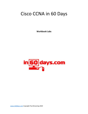
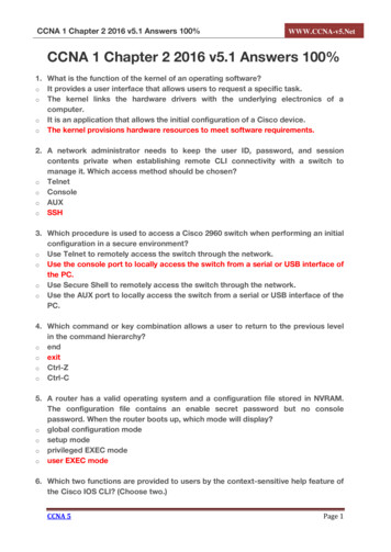
1. BASIC EXERCISESNote: Please refer to the below default network Diagram for all the exercises given in thismanual1.1: Lab Exercise 1: Entering User EXEC prompt on a Router, and exitDescription: A basic exercise, that shows how to enter into privileged EXEC prompt from usermode prompt, and exit from the same.Instructions:1. Enter into privileged mode2. Get back to the user modeVersion 4.0Copyright 2002 - 2019 CertExams.com6
BLR Password:CiscoBLR enableBLR#disableBLR Back1.2: Lab Exercise 2: Introduction to Basic User InterfaceDescription: This exercise helps to get familiar with the user mode, privileged mode, CLI andbasic commands.Instructions:1. Press enter to get the router prompt2. In the user mode, type the command ? used to view all the commands in user mode3. Enter into privileged mode4. In the privileged mode, type the command ? to view all the commands in privileged mode5. The command show ? displays all the show commands like show access-list, show banner,show cdp, show hosts, show flash, show protocols etc6.The command show running-config displays the running configuration7. Press space bar to view more information8. The command “exit or disable” logs out the routerBLR BLR ?BLR enableBLR#BLR#?BLR#show ?BLR#show running-configBLR#exitOrBLR#disableBack1.3: Lab Exercise 3: Basic show commandsDescription: A basic exercise to get familiar and understand the various show commandsavailable in the privileged mode.Instructions:1. Enter into privileged mode2. Show running-config displays the active configuration in memory. The currently activeconfiguration script running on the router is referred to as the running-config in the router’s CLI3. Show flash memory. Flash memory is a special kind of memory that contains the operatingsystem image file(s) on the router4. Show history command displays all the past commands still present in router’s memory5. Show protocols command displays the protocols running on your routerVersion 4.0Copyright 2002 - 2019 CertExams.com7
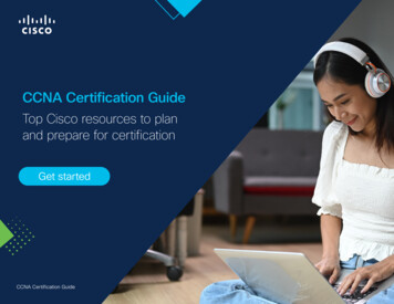
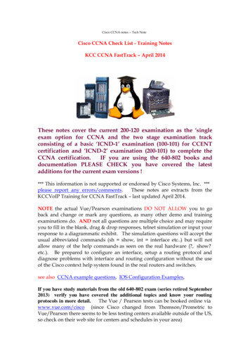
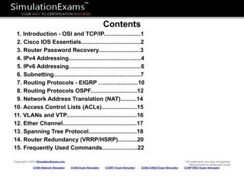
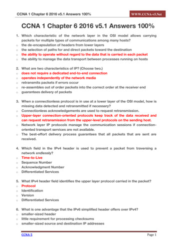
6. Show version command displays critical information, such as router platform type, operatingsystem revision, operating system last boot time and file location, amount of memory, number ofinterfaces, and configuration register7. Show clock command displays the router’s clock8. Show hosts command displays list of hosts and all their interfaces IP Addresses9. Show users command displays list of users who are connected to the router10. Show interfaces command displays detailed information about each interfaceBLR BLR enableBLR#show running-configBLR#show flashBLR#show historyBLR#show protocolsBLR#show versionBLR#show clockBLR#show hostsBLR#show interfacesBelow is the “show protocols” command outputBelow is the “show version “ command outputVersion 4.0Copyright 2002 - 2019 CertExams.com8
Below is the “show clock” command outputBack1.4 Short form commands1. copy running-config startup-config command can be interpreted and used in short form as“copy run start” command.2. show running-config command can be interpreted and used in short form as “show run”command.3. show startup-config command can be interpreted and used in short form as “show start”command.4. copy running-config tftp command can be interpreted and used in short form as "copy run tftp"command.5. copy tftp startup-config command can be interpreted and used in short form as "copy tftp start"command.Note: We can also use UP ARROW and DOWN ARROW keys to get the previously typedcommand in the simulator.Back2. ROUTING IOS FUNDAMENTAL EXERCISES2.1: Lab Exercise 1: Banner MOTD-Setting message of the dayDescription: This exercise helps in understanding the procedure of setting message of the dayand the show banner command. Note that the banner is set in a single command line here. Youcan also use multi-line banner motd command.Instructions:1. Enter into privileged mode2. Enter into global Configuration Mode3. Set banner to: "Welcome to local host". Starting and ending character of the banner should be"Z" (Do not use quotes)4. Use show banner command to view the banner that has been setBLR enableBLR#configure terminalBLR(config)#banner motd Z Welcome to local host ZBLR(config)#exitBLR#show running-configurationVersion 4.0Copyright 2002 - 2019 CertExams.com9
Back2.2: Lab Exercise 2: Setting Host NameDescription: This basic exercise illustrates the steps required to set a hostname to a router.Instructions:1. Enter into privileged mode2. Enter into global Configuration Mode3. Set hostname as ciscoBLR enableBLR#configure terminalBLR(config)#hostname ciscoBLR(config)#exitBLR#show running-configYou can give “show running-config” command to check the output ,where hostname changed tocisco from BLRBack2.3: Lab Exercise 3: Router Interface ConfigurationDescription: In this lab, you will learn to enable interfaces on a router i.e, configure Serial 0/0/0 andFastEthernet 0/0 interfaces on a router with specified IP Address and Subnet Mask.Instructions:Version 4.0Copyright 2002 - 2019 CertExams.com10
1. Enter into privileged mode2. Enter into global Configuration Mode3. Set IP Address of Serial 0/0/0 as 192.168.1.2 and Subnet Mask as 255.255.255.54. Set IP Address of FastEthernet 0/0 as 192.168.0.130 and Subnet Mask as 255.255.255.0BLR enableBLR#configure terminalBLR(config)#interface serial 0/0/0BLR(config-if)#ip address 192.168.1.2 ace fastethernet 0/0BLR(config-if)#ip address 192.168.0.130 255.255.255.0By giving “show running-config” command you can view the ip address configured on the interfacesBack2.4: Lab Exercise 4: Setting Bandwidth on an interfaceDescription: Bandwidth refers to the rate at which data is transferred over the communicationlink. You setup the bandwidth on a given interface (interface serial 0/0/0) to a specified value (64kbps). You also set the clockrate to 64000. Note that bandwidth is represented in kbps whereasclock rate is entered in bps.Syntax: bandwidth (interface):The command bandwidth kilobits will set and communicate the bandwidth value for aninterface to higher-level protocols.Ex: bandwidth 64 will set the bandwidth to 64 kbps. Use no form of the command to set theVersion 4.0Copyright 2002 - 2019 CertExams.com11
bandwidth to default value.Instructions:1. Enter to serial 0/0/0 mode of router BLR2. Set bandwidth of serial 0/0/0 as 64 kbps3. Set clockrate as 64000 bpsBLR enableBLR#configure terminalBLR(config)#interface serial 0/0/0BLR(config-if)#bandwidth 64BLR(config-if)#clock rate 64000 - This command applies to only DCE how interface s 0/0/0BLR#show interfacesBelow is the show interfaces serial 0/0/0” command outputBack2.5: Lab Exercise 5: Setting Console PasswordNot Available in Demo Version2.6: Lab Exercise 6: Setting Telnet PasswordNot Available in Demo VersionVersion 4.0Copyright 2002 - 2019 CertExams.com12
2.7: Lab Exercise 7: Setting Auxiliary Password to RouterNot Available in Demo Version2.8: Lab Exercise 8: Configuring Minimum password lengthNot Available in Demo Version2.9: Lab Exercise 9: Implementing exec-timeout commandNot Available in Demo Version2.10: Lab Exercise 10: Copy Running Configuration to Startup ConfigurationNot Available in Demo Version2.11: Lab Exercise 11: Router CDP ConfigurationNot Available in Demo Version2.12: Lab Exercise 12: Show CDP ConfigurationNot Available in Demo Version2.13: Lab Exercise 13 : Show CDP NeighborsNot Available in Demo Version2.14: Lab Exercise 14: Bringing-up a router InterfaceNot Available in Demo Version2.15: Lab Exercise 15: Set Keepalive TimersNot Available in Demo Version2.16: Lab Exercise 16: Set Hostname and MOTD BannerNot Available in Demo Version2.17: Lab Exercise 17: Configuring enable and secret pasword and servicepassword-encryptionNot Available in Demo VersionVersion 4.0Copyright 2002 - 2019 CertExams.com13
2.18: Lab Exercise 18: Host TableNot Available in Demo Version2.19: Lab Exercise 19: Viewing ARP EntriesNot Available in Demo Version2.20: Lab Exercise 19: TelnetNot Available in Demo Version2.21: Lab Exercise 20: TFTPNot Available in Demo Version2.22 Lab Exercise 22: Configuring Cisco Routers for SyslogNot Available in Demo Version2.23 Lab Exercise 23: Configure and Verify NTPNot Available in Demo Version3. EXERCISES ON ROUTING FUNDAMENTALS3.1: Lab Exercise 1: Introduction to IPDescription: This lab exercise is to learn assigning IP address to routers and pinging betweenthem to test connectivityInstructions:1. Connect to router BLR, configure its ip address of serial interfaces2. Connect to router NY, configure its ip address of serial interfaces.3. Connect to router LD, configure its ip address of serial interfaces.4. Use the command “show ip interface brief” to verify that the lines and protocols are up forall NY's interfaces5. Display NY’s running configuration to verify that the IP addresses appear6. Display detailed IP information about each interface on NYBLR enableBLR#configure terminalBLR(config)#interface serial 0/0/0BLR(config-if)#ip address 192.168.1.2 255.255.255.0BLR(config-if)#no shutdownVersion 4.0Copyright 2002 - 2019 CertExams.com14
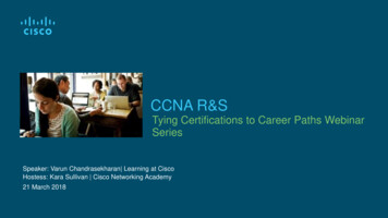
BLR(config-if)#exitBLR(config)#interface serial 0/1/0BLR(config-if)#ip address 192.168.3.1 255.255.255.0BLR(config-if)#no shutBLR(config-if)#exitNY enablePassword:CiscoNY#configure terminalNY(config)#interface serial 0/0/0NY(config-if)#ip address 192.168.1.1 255.255.255.0NY(config-if)#no shutdownNY(config-if)#exitNY(config)#interface serial 0/1/0NY(config-if)#ip address 192.168.2.1 255.255.255.0NY(config-if)#no shutdownLDN enablePassword:CiscoLDN#configure terminalLDN(config)#interface serial 0/0/0LDN(config-if)#ip address 192.168.2.2 255.255.255.0LDN(config-if)#no shutdownLDN(config-if)#exitLDN(config)#interface serial 0/0/1LDN(config-if)#ip address 192.168.3.2 255.255.255.0LDN(config-if)#no shutdownLDN(config-if)#exitNY#ping 192.168.2.2NY#ping 192.168.3.2NY#show ip interface briefNY#show running-configNY#show ip interfaceThe sample output of “show ip interface brief” command on router NY is shown belowBackVersion 4.0Copyright 2002 - 2019 CertExams.com15
3.2: Lab Exercise 2: Configuring Static RoutesDescription: Configure static route 10.10.1.0 mask 255.255.255.0 with next hop address of192.168.1.1Syntax: ip route prefix mask {address interface} [distance]prefix mask: It is the ip route prefix and mask for the destination.address interface: Use either the next hop router ip or the local router outbound interface used toreach the destination.distance: It is the administrative distance and an optional parameter.Instructions:1. Enter into Global Configuration Mode2. Disable IP Routing3. Re-enable IP Routing4. Configure a static route with destination sub network number as 10.10.1.0 with subnet mask as255.255.255.0, and IP address of the next-hop router in the destination path to 192.168.1.1BLR enableBLR#configure terminalBLR(config)#no ip routingBLR(config)#ip routingBLR(config)#ip route 10.10.1.0 255.255.255.0 192.168.1.1Note: “no ip routing” command used in the above exercise is used to remove any previouslyconfigured routing information.Back3.3: Lab Exercise 3: Implement and Verfiy Static RoutesNot available in Demo Version3.4: Lab Exercise 4: Configuring Default RouteNot available in Demo Version3.5: Lab Exercise 5: Implement and Verify Default RoutesNot available in Demo Version3.6: Lab Exercise 6: Configuring Loopback InterfaceNot available in Demo Version3.7: Lab Exercise 7: Connectivity Tests with TracerouteNot available in Demo VersionVersion 4.0Copyright 2002 - 2019 CertExams.com16
3.8: Lab Exercise 8: Configuring RIPNot available in Demo Version3.9: Lab Exercise 9: Basic EIGRP RoutingNot available in Demo Version4. EXERCISES ON RIP/EIGRP Routing Scenarios4.1: Lab Exercise 1: RIP Routing Configuration ScenarioDescription: The purpose of this exercise is to configure RIP on all the devices and test for pingand trace commands.The router rip command selects RIP as the routing protocol.The network command assigns a major network number that the router is directlyconnected to. The RIP routing process associates interface addresses with the advertised networknumber and begins RIP packet processing on the specified interfaces.Instructions:1. Assign the IP address of all the devices as given below2. Bring all the interfaces to up3. Configure RIP on all the devices4. From NY issue a ping and trace command to BLR and LDNVersion 4.0Copyright 2002 - 2019 CertExams.com17
Device Interface IP /0192.168.1.2S0/1/0192.168.3.1LDN S0/0/0192.168.2.2S0/0/1192.168.3.2On 55.255.0255.255.255.0255.255.255.0NY enableNY#configure terminalNY(config)#interface serial 0/0/0NY(config-if)#ip address 192.168.1.1 255.255.255.0NY(config-if)#no shutdownNY(config-if)#exitNY(config)#interface serial 0/1/0NY(config-if)#ip address 192.168.2.1 255.255.255.0NY(config-if)# no shutdownNY(config-if)#exitNY(config)#router ripNY(config-router)#network 192.168.1.0NY(config-router)#network 192.168.2.0On BLRBLR enableBLR#configure terminalBLR(config)#interface serial 0/0/0BLR(config-if)#ip address 192.168.1.2 255.255.255.0BLR(config-if)# no shutdownBLR(config-if)#exitBLR(config)#interface serial 0/1/0BLR(config-if)#ip address 192.168.3.1 255.255.255.0BLR(config-if)#no shutdownBLR(config-if)#exitBLR(config)#router ripBLR(config-router)#network 192.168.1.0BLR(config-router)#network 192.168.3.0On LDNLDN enableLDN#configure terminalLDN(config)#interface serial 0/0/0LDN(config-if)#ip address 192.168.2.2 255.255.255.0LDN(config-if)# no shutdownLDN(config-if)#exitVersion 4.0Copyright 2002 - 2019 CertExams.com18
LDN(config)#interface serial 0/0/1LDN(config-if)#ip address 192.168.3.2 255.255.255.0LDN(config-if)#no shutdownLDN(config-if)#exitLDN(config)#router ripLDN(config-router)#network 192.168.3.0LDN(config-router)#network 192.168.2.0On NY:NY#ping 192.168.3.2NY#ping 192.168.3.1NY#trace 192.168.3.2NY#trace 192.168.3.1Back4.2: Lab Exercise 2: Viewing IP RIP InformationDescription: The purpose of this exercise is to view important information on IP RIP.Show ip route command displays the current state of the routing table and this command is to beused in EXEC mode.Show ip protocols command displays the parameters and current state of the active routingprotocol processes and this command is to be used in EXEC mode.Instructions:1. Enter global configuration mode, and enable RIP routing on the router2. Associate network 192.168.1.0 with RIP routing process3. Issue the command that displays all entries in the Routing Table4. Type the command that displays information about the IP routing protocolsNY enableNY#configure terminalNY(config)#interface s 0/0/0NY(config-if)#ip address 192.168.1.1 255.255.255.0NY(config-if)#no shutdownNY(config-if)#exitNY(config)#router ripNY(config-router)#network #show ip routeNY#show ip protocolsBelow is the show output of “show ip route” commandVersion 4.0Copyright 2002 - 2019 CertExams.com19
Below is “show ip protocols” command output where ip protocol configured is RIP.Back4.3: Lab Exercise 3: Configuring RIPV2Not available in Demo Version4.4: Lab Exercise 4: RIP2 RoutesNot available in Demo Version4.5: Lab Exercise 5: EIGRP Routing Configuration ScenarioNot available in Demo VersionVersion 4.0Copyright 2002 - 2019 CertExams.com20
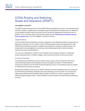
4.6: Lab Exercise 6: EIGRP Troubleshooting Lab ScenarioNot available in Demo Version4.7: Lab Exercise 7: EIGRP Show CommandsNot available in Demo Version5. Exercises on OSPFNote: Please refer to the below network Diagram for all the exercises in this section5.1: Lab Exercise 1: OSPF Configuration in Single AreaDescription: In OSPF single area, you configure OSPF network with an area ID. Theconfiguration example uses four routers working in area 200.IP Address Assignment TableDevice Interface IP AddressVersion 4.0MaskCopyright 2002 - 2019 CertExams.com21
Instructions:1. Based on the given network configuration, use appropriate commands to configure OSPF innetworks 192.168.1.0, 192.168.2.0, 192.168.3.0 and 192.168.4.0 within area 2002. Ping LDN and LA from NY and verify connectivity3. Ping NY and LDN from LA and verify connectivityOn NY:NY enableNY#configure terminalNY(config)#interface serial 0/0/0NY(config-if)#ip address 192.168.1.1 255.255.255.0NY(config-if)# no shutdownNY(config-if)#exitNY(config)#interface serial 0/1/0NY(config-if)#ip address 192.168.2.1 255.255.255.0NY(config-if)# no shutdownNY(config-if)#exitNY(config)#interface serial 0/1/1NY(config-if)#ip address 192.168.4.1 255.255.255.0NY(config-if)# no shutdownNY(config)#router ospf 1NY(config-router)#network 192.168.1.0 0.0.0.255 area 200NY(config-router)#network 192.168.2.0 0.0.0.255 area 200NY(config-router)#network 192.168.4.0 0.0.0.255 area 200NY(config-router)#exitNY(config)#exitNY#On BLRBLR enableBLR#configure terminalBLR(config)#interface serial 0/0/0BLR(config-if)#ip address 192.168.1.2 255.255.255.0BLR(config-if)# no shutdownBLR(config-if)#exitBLR(config)#interface serial 0/1/0Version 4.0Copyright 2002 - 2019 CertExams.com22
BLR(config-if)#ip address 192.168.3.1 255.255.255.0BLR(config-if)# no shutdownBLR(config-if)#exitBLR(config)#router ospf 1BLR(config-router)#network 192.168.1.0 0.0.0.255 area 200BLR(config-router)#network 192.168.3.0 0.0.0.255 area 200BLR(config-router)#exitBLR(config)#exitBLR#On LDNLDN enableLDN#configure terminalLDN(config)#interface serial 0/0/0LDN(config-if)#ip address 192.168.2.2 255.255.255.0LDN(config-if)# no shutdownLDN(config-if)#exitLDN(config)#interface serial 0/0/1LDN(config-if)#ip address 192.168.3.2 255.255.255.0LDN(config-if)# no shutdownLDN(config)#router ospf 1LDN(config-router)#network 192.168.2.0 0.0.0.255 area 200LDN(config-router)#network 192.168.3.0 0.0.0.255 area 200LDN(config-router)#exitLDN(config)#exitLDN#On LALA enableLA#configure terminalLA(config)#interface serial 0/0/0LA(config-if)#ip address 192.168.4.2 255.255.255.0LA(config-if)# no shutdownLA(config-if)#exitLA(config)#router ospf 1LA(config-router)#network 192.168.4.0 0.0.0.255 area 200LA(config-router)#exitLA(config)#exitLA#On NYNY#ping 192.168.3.2NY#ping 192.168.4.2On LALA#ping 192.168.1.1Version 4.0Copyright 2002 - 2019 CertExams.com23
LA#ping 192.168.2.2Back5.2: Lab Exercise 2: OSPF Troubleshooting Lab Scenario-1Description: In OSPF single area, you configure OSPF network with an area ID.The configuration example uses four routers working in area 200.IP Address Assignment TableDevice Interface IP 192.168.3.2Instructions:1. Assign IP Addresses on all the devices as per the above table and bring all the interfaces to upstate2. On NY enable OSPF routing with process 1 and area as 200 for the network 192.168.2.0 and192.168.4.03. On BLR enable OSPF routing with process 1 and area as 200 for the network 192.168.1.0 and192.168.3.04. On LDN enable OSPF routing with process 1 and area as 200 for the network 192.168.2.0 and192.168.3.05. On LA enable OSPF routing with process 1 and area as 200 for the network 192.168.4.06. Ping NY from BLR, you will see ping failure7. Ping BLR from LDN, you will see ping success (This implies connectivity failure from BLR toNY)8. Issue command on NY to see OSPF database9. You will see that there is no link state entry for network 192.168.1.0, so enable OSPF routingon NY for this network10. Ping NY from BLR, you will see ping successNote: You need to assign the IP addresses and make the interfaces up (by issuing no shutdowncommands at appropriate interfaces) for all the devices before proceeding with the followingcommandsOn NY:NY enableNY#configure terminalVersion 4.0Copyright 2002 - 2019 CertExams.com24
NY(config)#interface serial 0/0/0NY(config-if)#ip address 192.168.1.1 255.255.255.0NY(config-if)# no shutdownNY(config-if)#exitNY(config)#interface serial 0/1/0NY(config-if)#ip address 192.168.2.1 255.255.255.0NY(config-if)# no shutdownNY(config-if)#exitNY(config)#interface serial 0/1/1NY(config-if)#ip address 192.168.4.1 255.255.255.0NY(config-if)# no shutdownNY(config)#router ospf 1NY(config-router)#network 192.168.2.0 0.0.0.255 area 200NY(config-router)#network 192.168.4.0 0.0.0.255 area 200NY(config-router)#exitNY(config)#exitOn BLRBLR enableBLR#configure terminalBLR(config)#interface serial 0/0/0BLR(config-if)#ip address 192.168.1.2 255.255.255.0BLR(config-if)# no shutdownBLR(config-if)#exitBLR(config)#interface serial 0/1/0BLR(config-if)#ip address 192.168.3.1 255.255.255.0BLR(config-if)# no shutdownBLR(config-if)#exitBLR(config)#router ospf 1BLR(config-router)#network 192.168.1.0 0.0.0.255 area 200BLR(config-router)#network 192.168.3.0 0.0.0.255 area 200BLR(config-router)#exitBLR(config)#exitBLR#On LDNLDN enableLDN#configure terminalLDN(config)#interface serial 0/0/0LDN(config-if)#ip address 192.168.2.2 255.255.255.0LDN(config-if)# no shutdownLDN(config-if)#exitLDN(config)#interface serial 0/0/1LDN(config-if)#ip address 192.168.3.2 255.255.255.0LDN(config-if)# no shutdownLDN(config)#router ospf 1LDN(config-router)#network 192.168.2.0 0.0.0.255 area 200LDN(config-router)#network 192.168.3.0 0.0.0.255 area 200Version 4.0Copyright 2002 - 2019 CertExams.com25
LDN(config-router)#exitLDN(config)#exitLDN#On LALA enableLA#configure terminalLA(config)#interface serial 0/0/0LA(config-if)#ip address 192.168.4.2 255.255.255.0LA(config-if)# no shutdownLA(config-if)#exitLA(config)#router ospf 1LA(config-router)#network 192.168.4.0 0.0.0.255 area 200LA(c
14.6 Lab Exercise 6: Enabling OSPF for IPv6 on a cisco router interface 14.7 Lab Exercise 7: Configuring OSPF on two router interfaces 14.8 Lab Exercise 8: General IPv6 configuration on series router 14.9 Lab Exercise 9: Traceroute lab 15. Exercises on BGP 15.1 Lab Exercise 1: Basic BGP