Transcription
Fashionable prototyping and wearable computing using the Arduino
Copyright 2008 Tony Olsson, David Gaetano, Jonas Odhner, Samson Wiklund.First Edition. Some Rights Reserved.This book is licensed under the terms of Creative Commons Attribution-NonCommercialNoDerivs 3.0 license available from http://www.creativecommons.org/. Accordingly, you are free tocopy, distribute, display, and perform the work under the following conditions:1 you must give the original author credit.2 you may not use this work for commercial purposes.3 you may not alter, transform, or build upon this work.For any reuse or distribution, you must make clear to others the license terms of this work. The bestway to do this is with a link to this web page.www.creativecommons.orgAny of the above conditions can be waived if you get permission from the copyright holder. Nothingin this license impairs or restricts the author’s moral rights.
Open softwearfashionable prototyping and wearablecomputing using the Arduino
PrefaceThe content of this book is inspired by the teachings of the physicalprototyping laboratory in the school of art and communication, atthe University of Malmö.The physical prototyping laboratory, run by David Cuartielles, hassome of the longest running university courses based on the Arduino platform where Arduino has been a active part of the curriculum in Fashion, body and technology, Light Installation and inthe Interaction programs at both bachelors and masters level, since2005.Until resent years students of the fashion body and technologycourse have been introduced to physical prototyping in a old fashion “hard“ way. Earlier focus has been on transferring technologyinto the context of fashion and wearable computing.However, in recent years, steps have been taken to implementtechnology into the context of fashion in a “softer” way. Prior tothis, the experience from teachers at physical prototyping laboratory has been that students with an interest in fashion and wearablecomputing have had a hard time transferring the standard physicalprototyping knowledge into prototype development of a wearablecharacter.When searching for suitable material to base our new approach tothe field we soon realized that the available information was quietlimited and most of the material was of a “arts and craft” character.We a strong believer int the DIY movement and still think thereis much to learn form the “arts and craft” materials out there but Ithink that a course at university level should be able to offer morecomplex approach than what can be learned for “do it your selfguides”.Form my earlier experience of both attending and teaching thenormal prototyping courses K3 Malmö my opinion is that the Arduino platform used, is that it is one of the best prototyping platforms currently available for two simple reasons. The price and thecommunity. Both reasons are connected to the philosophy of the5
Arduino and the Arduino is quite unique since it is both open software and hardware.The goal with Arduino was to create a prototyping platform fordesigners to be able to realize there ideas by them selfs. And theopenness in the Arduinos own design means that anyone is freeto make modification to both the hardware and software or evenproduce and sell the actual boards.This in turn means that the priceof the Arduino is available at a very affordable level since anyone isallowed to compete in the manufacturing.The price in turn is also one of the main reasons to large numberof users and its these users that is the Arduino community. This isa community that share a common love for prototyping and sharethe Arduinos philosophy of openness which not only means thatthere is a lot of information and help to be found. It also meansthat Arduino community also is one of the most current and rapidin pushing the evolution of prototyping forward. With this in midthe question has never been to move away from the Arduino whenapproaching the field of fashion and technology but rather how canwe approach the field in a “softer way” using the Arduino.Most of the development in the course has focused on comparingprojects from active people in the field of fashion and wearablecomputing to the teachings at the University to find softer alternatives to the normal “hard“ components. The goal has been to usethe same basic principles used in “hard technology” and implementing them in a “soft” way to help the understanding of technology in terms that could be considered more naturally for peopleapproaching physical prototyping from a textile background.With the use of the Arduino I also hope to add what I consider onemissing key feature that is missing in the “art and craft” momentsapproach to fashion and technology and that is the possibility ofcomputing information.This book isn’t solely aimed at people with an academic interest inthe field of fashion and technology and wearable computing butshould also be considered as a start up guide for any one with ageneral interest in the subject.6
It has been my aim to follow the teaching philosophy of DavidCuartielles and the physical prototyping team at K3 Malmö. It is asimple philosophy that can best be compared to punk rock. Punkrock took the approach that you don’t have to know everythingabout music to play music. If you know three basic accords thatis enough to make a song. The same goes for prototyping. Onceyou know a couple of basic programming commands and how toconnect something simple like a LED, then you can start building.Knowledge about prototyping comes from doing, not reading. Butstill you need some basic accords to play and I hope that the following chapters will get you started.Tony7
ContentsPart one: BasicsChapter 1: IntroductionChapter 2: HardwareChapter 3: SoftwareChapter 4: Using the IDEPart two: ExamplesChapter 5: Using digital PinsChapter 6: Using analog pinsChapter 7: Moving stuffChapter 8: Complex examples1317252937515963Part three: CodingChapter 9: Writing ProgramsEpilogueIndex7599103
Part one: BasicsIntroduction to wearable computing.
Chapter 1: IntroductionPrototyping with the ArduinoThe Arduino prototyping platform is based on a simple work progress of using inputs and outputs. The inputs are usually some formof button, switch or sensor. Buttons are usually only on and off butwith sensor you can measure your environment in a variety of ways.Sound, movement, temperature and light can all be processed by theArduino and if you can think of any other behaviors that you wantto measure, chances are that there already exists a sensor for it.In the same way that you can connect a large amount of inputs,you can control a large scale of outputs. An output can be anythingfrom light, movement, heat to more complex outputs like sendingan SMS or even turning a TV off on the other side of the world. Inmost cases there already exists a technical solution for your prototype, you just have to find them.Since the Arduino at heart is a micro controller, everything youconnect to it has to be electrical. The good thing is that nearly everything can be translated into a electrical signal. For example, whena human is touched by something a signal is sent to the brain thatthere is a sensation somewhere on the body. In the same way we canmake an electric line from the Arduino and back to it. If somethingbreaks this line of electricity a signal is sent back to the brain of theArduino to tell it that there is no electricity in the line.Hacking: save money, learn moreOnce you have started to play around with making your own electric prototypes you will soon realize that a lot of electronic components costs a fare amount of money. It’s therefore most peopleinterested in electric prototyping have their other foot in hardwarehacking.Hardware hacking is also known as tinkering and it describes theactivity of breaking commercial electrical products apart just to see“what makes them tick”.Tinkering isn’t just a good way to learn more about how electric13
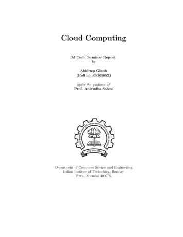
things work but it’s also an efficient way to save money. A lot ofcomponents you may need for your projects can be found in what’snormally considered junk. An old printer has a motor that mightstill be functional, an old phone has nice batteries and small vibrators and cheap electric toys are often goldmines.There’s no right or wrong way of hacking and tinkering whichalso means theres no official instructions on how to do it. But theinternet is full of information and tips on tinkering and the Arduino www.arduino.cc/playground, www.makezine.com and www.instructables.com are great resources to get you started.How electricity worksThere are a few things you need to know about electricity to makeyour own electronic prototypes. First of all electricity always needto go back to where it came from to make a circuit.In the following example we have connected a LED to a batterywith a switch:LEDPushbutton3.5 volt BatteryThe power from the battery will travel through the cable into theLED in one leg and out the other down to the button and back tothe battery.14
Buttons normally connect a small piece of metal with another onewhen you push it. If the button isn’t pushed nothing will happenbut when you push it you make a connection with the metal platesand the power from the battery can travel back to where it camefrom. Once it comes back to the battery the LED lights up. In theabove example there is a 3.3V battery and a LED that can handle3.3V of electricity. If we connected a 9V battery instead the LEDwould burn. This is because electricity have different types of voltand ampere and it travels with different resistance.Imagine electricity like water. The speed of the water would be thesame as the volt and the amount of water traveling would be thesame as the amperes. Lets say we let our water through a gardenhose then the garden hose would be the same as the resistance forelectricity. So to connect the LED to 9V battery would be likepushing to much water to fast through a garden hose. If the gardenhose cant let all the water through the hose will burst.It’s very rare that that things explode when making prototypes withthe Arduino since most prototypes are made with such low voltageit’s hard to even consider them harmful. But still it’s never a goodidea to connect more power to something than it can handle sincethere’s a good chance you’ll brake it. So always follow the recommended power restrictions for you components.15
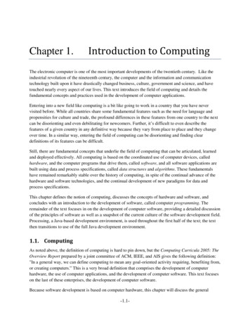
Chapter 2: HardwareArduinoThe Arduino is an open source micro controller board used forelectronic prototyping. The Arduino can receive data from sensorsused to collect information in its soundings and it can be used tocontrol other electronic components as lights, motors and more.There are varieties of Arduinos available and the most commonone is the latest version of the standard Arduino board which lookslike this:41The most important parts on theArduino board high lighted in red:73261:2:3:4:5:6:7:USB connectorPower connectorAutomatic power switchDigital pinsAnalog pinsPower pinsReset switch5The USB connector (1) is used for connecting your Arduino boardto your computer. While connected the Arduino board will bepowered from the USB cable and while connected you can uploadcode and you can communicate from and to your Arduino board.The power connector (2) is used when you don’t want to poweryour Arduino with the USB cable. Instead you can use a normaltransformer (power adapter) in the range from 6V to 24V.Note:Although the Arduino has an on boardpower regulator, make shure to neverconnect a power source that is largerthan 24V. Chances are that you willdestroy your Arduino board.17
The Arduino can also run on batteries. On Arduinos earlier than theDuemilanove version you need to manually switch power sourceon the Arduino. This is done by switching the plastic jumper (3)located between the USB connector and the power connector. Ifyou want to power the Arduino with the USB you put the jumperover the two pins closest to the USB connector and if you want anexternal power source you put the jumper over the two pins closestto the power connector. On versions later than the Duemilanovethe Arduino automatically choses the power source.There are 13 digital pins (4) on the Arduino board and these can beused as both inputs and outputs depending on how you set themein your program:The analog pins (5) work only as input (this is not completely truesince you can reprogram these pins to digital ones but this requiressome Arduino knowledge) but can handle a larger range of incoming information then what the digital pins can:Note:GND is short for ground.To the left of the analog pins you will find the power pins (6). Fromhere you can pull either 3.3V or 5V. The pin named vin will giveyou whatever is connected to the power jack. If you have 12V connected to the power jack, you will be able to pull the same from thispin. Here you also can find two GND pins.The reset switch (7) is used to reset any program on the Arduinoto start from its beginning. On Arduinos older than the Diecimilaversion of the Arduino, the reset button needs to be pushed everytime you try to upload code.For the examples in this book we have chosen to use the standardArduino board since it is our opinion that this is the best boardfor prototyping. When you are close to finalizing you prototypes itcan be useful to migrate to one of the other smaller boards to savespace.These board work the same way and any program written fora standard Arduino board will work on all other types of Arduinos.The following are two other examples of Arduino boards available.18
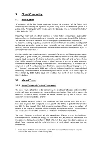
LilyPadThe LilyPad Arduino is a micro controller board designed for wearables and e-textiles. It can be sewn to fabric and similarly mountedpower supplies, sensors and actuators with conductive thread. Theboard is based on the ATmega168V chip (the low-power version ofthe ATmega168) The LilyPad Arduino was designed and developedby Leah Buechley and SparkFun Electronics.231/tx0/rxBa5a4a3G4a2-a1 a0Note:ATmega 168 is an electronic integrated circuit microcontroller producedby the Atmel corporation. It has thebasic Atmel AVR instruction set. Formore information about Atmel andthe ATmega chip family visit the Atmelsite:www.atmel.comNote:To learn more about the hardwareof the standard Arduino board or forinformation on other Arduino boardsvisit the Arduino site:www.arduino.cc. ard.1351267891011Arduino miniThe Arduino Mini is a small micro controller board based on theATmega168, intended for use on breadboards and when space isat a premium. It has 14 digital input/output pins (of which 6 canbe used as PWM outputs), 8 analog inputs, and a 16 MHz crystaloscillator. It can be programmed with the mini USB adapter orother USB or RS232 to TTL serial adapter (www.arduino.cc). Ifyou remove the male pins from this board it can be sewn to a pieceof fabric using conductive thread.19
Basic electronic components for soft prototyping Conductive threadThis type of thread looks like normal grey thread but it has thepossibility to carry currents for power and signals. The conductivethread can be used instead of normal cables to power your electronics and it is very suitable for working with “soft” prototyping.Conductive threads come in different thicknesses and with differentresistances. The resistance in the thread lowers the pressure of thevoltage in the power supply you are using. The resistance of thethread is normally calculated per meter so remember the simpleprinciple that more thread equals more resistance. ResistorsA resistor is an electronic component designed to oppose an electriccurrent by producing a voltage drop between its terminals in proportion to the current. Resistance is always measured in ohm andcan also be presented as the symbol Ω. The most common multipliers for resistance calculations is:kilo ohm which is the same as a 1’000 Ωmegohm which is the same as 1’000’000 ΩAll resistors are color coded. Resistors can have 4, 5 or 6 colderbands and it is these bands that tell you the resistance of the resistor.The first three bands are digits that follow this color digit ywhite200123456789
If the three bands are brown, red and blue this would translated to126. The forth band is the multiplier. You multiple the first threedigit by this band and then you get the resistance of your resistor.The fourth band follows the below color epurple0.010.11101001k10k100k1M10MThe fifth band is the tolerance of the resistor and the sixth band isused for temperature coefficient. It’s hard to learn resistor calculations by heart so it recommended to use a online resistor calculatorto be certain. If you google “resistor calculator” you will find a lotof them.Note:The third digit is not used on fourband resistors. Four band resistoronly use two digits, the third band isthe multiplier and the fourth is thetolerance. LEDA light emitting diode (LED) is a semi conducting diode that lightsup when electric current is applied in the forward direction of theLED. There are three different ways of telling the forward directionof a LED. The first is to look at the legs of the LED. There will beone that is longer.This long leg will be the one connected to wherethe power comes from and the short leg needs to be connected tothe ground of the power source(1). The second way to tell whatway of a LED is to look at the shape of the plastic bubble(2). Thelower rim of the bubble should have one side that is flat and it isthe leg of that side that should go to you power and the other sideshould go to ground. The third way is to hold a LED up to a lightand have a look inside. There will be two pegs, one small and onebig(3). The leg that goes to the small peg is the one that should beconnected to the ground and the leg on the big peg should be connected to power.32121
The most common LEDs are powered in the vicinity of 3.3V and20mA. Note that the Arduino will always supply 5V from the digitalpins. This is why we will use a resistor of 220 Ω to lower the powerso we won’t burn the LED.To be sure what power your LED needs,have a look at the data sheet for your LED.This information is oftenavailable with the electric components you buy. If you need to calculate what resistance to use for your LED I recommend you usean online resistor calculator. Conductive fabricConductive fabrics are normally a combination of highly conductive metals and lightweight fabrics and is often used as a shieldingmaterial. Conductive fabrics have the ability to conduct electricity. Tilt sensorA tilt sensor is a sensor that can detect if a object is tilting to oneside or another. The cheapest kind of tilt sensor can also be usedas a measurement for movement. The drawback of this kind of tiltsensor is that they work as a pushbutton so they cant be used totell which direction an object is tilting or how much, only that theobject is tilting.Inside the tilt sensor there is a small metal ball inside a metal casing.Once the ball touches the sides of the metal casing it will completea circuit and we can read it from the Arduino board. LDR sensorLDR stands for Light Dependent Resistor and is also known as aphotoresistor. An LDR is made of a high resistance semiconductor. The LDR is similar to a normal resistor with the exceptionthat normal resistor have fixed values and the LDR:s resistance isdependent on light in its vicinity. It is very hard to use an LDR todetermine an exact amount of light in a given setting but they aregood enough to use for determining light in a broader sense - if itsdark or light.22
NTC sensorNTC stands for Negative Temperature Coefficient and is also knowas a thermistor. A thermistor is a type of resistor that changes its resistance according to temperature. It’s hard to use a thermistor to tellexact temperature but they’re still good enough to make estimates ifsomething is cold or hot. MotorsIf you want to move something you probably need a motor of somesort. A motor is more or less an actuator that turns electricity intomovement. While working with hidden wearable prototypes motors can become and issue if you need a lot of force. Most motorsfollow the simple principle “the bigger the force, the bigger themotor”. There are still lots of small motor that could be relevantand with some creativity motors can be nicely integrated in yourprototypes.There are three main types of motors: DC motors, Servo motorsand stepper motors.We have not included any examples of stepper motors in this book.Though stepper motors are good for moving in full rotation andin steps, they’re not appropriate to implement into wearable technology since they are both heavy for there size and quite bulky intheir shape. If you are considering using motors it’s recommendedthat you find either a DC motor or a Servo motor that fits yourprototype. WiresWires are thin conductive metal threads placed inside a plastic casing, theycome in a wide range of sizes and colors. It’s good prototyping behaviourto color code your wires so you consistenly use the same colors.The common color use is GND black, PWR red and then the pins can haveany other color.Note:When we’re using wires it’s goodprototyping behaviour to curl theexposed metal core to make it easierto sew in place.23
Chapter 3: SoftwareThe software used to write programs for your Arduino is called theArduino IDE (Integrated Development Environment). The Arduino IDE is based on another open source programing language andprogram called Processing used for programing images, animationsand computer interactions. The Arduino IDE looks very similar tothe Processing IDE:The above is the Processing IDE and below you can see the Arduino IDE:25
Even the Arduino coding language is molded after the Processing language.The Arduino language is based on easy to usecommands and every time you press the upload button in theArduino IDE it will translate you program in to C code so theArduino board can understand your program. The languageis built this way since C programming is quite hard to use forfirst time programmers.Installing the softwareThe software can be found on the www.arduino.cc site under “downloads”. Once you have found the download pagechoose the right version for your operating system. When youhave downloaded the software, uncompress it and put the Arduino folder on your desktop. For XP usersAfter you have done all the steps in previous section, take yourArduino board and connect to your computer with the USBcable. Now Windows will tell you that it found a new USBdevice and it needs the drivers. Redirects the program to thedrivers folder inside your Arduino folder and install the drivers:desktop/Arduino/drivers/After you have done this one time Windows will ask you theyet another time for new drivers. Redirect the program onceagain to the same folder and install one more time. For Vista usersGo to www.ftdichip.com and in the “drivers” section locatethe D2XX driver and download it, double click on it and install the drivers. Then connect your Arduino to the computerwith a USB cable.Vista will tell you that it found a new deviceand that it needs the driver for it. Redirect it to the driversfolder inside the Arduino folder:desktop/Arduino/drivers/26
After you have done this one time Windows will ask you the yetanother time for new drivers. Redirect the program once again tothe same driver and install one more time. For OSX usersOpen the Arduino folder and then the drivers folder. Choose theright driver for your processor and double click on it. This willinstall the drivers needed and it will force you to restart your computer.27
Chapter 4: Using the IDEThe IDE consists of two large spaces, one white and one black.The white space is where you will write your program. Note thatanything you write in here will be considered as code if you don’t“comment it”. To learn more on how to hide text in your codeturn to page ?.The IDE buttons:CompileStopNew SketchOpen SketchSave SketchUploadSerial monitorThe black space is where you will receive error and confirmationmessages. Above the white space you will find the IDE buttons.With these buttons you control most of the actions in the IDE.The first one is the compile button. This button makes a check ofyour program to see if there’s any logical errors in your code.The second button is the stop button. This button is used to turnoff the serial monitor. The compiler will take as much time as itneed but don’t worry, compiling usually only takes a few secondsdepending one how big your program is.Note:The IDE only makes a logical checkand can’t determine if the programcorresponds to what you want theprogram to do.Once you started to compile youcan’t stop the compilation with thestop button.The third button is the new sketch button. In the Arduino IDE allprograms you open or write are called sketches. The new sketchbutton will open a new sketch for you, but will first ask if you wantto save your present sketch.29
The fourth button is the open sketch button. This button opensthe sketches folder and here you can choose to open already savedsketches.The fifth button is the save button. This button saves the presentsketches in the folder named sketchebook.The sixth button is the upload button. This button will upload thepresent program to your Arduino board assuming there is no errorsin your code. The upload button will first try to compile your codeand if it finds any errors it will stop compiling and a error messagewill appear in the black window of the IDE, telling you what theproblem is and the IDE will highlight the line of code that is causing the problem.The last button is the serial monitor button. This button will openyour serial monitor in the black space at the bottom of the IDE.Some times it can get confusing to tell if the serial monitor is openor not.The thing that tells the serial monitor apart from the normalblack space is that when the serial monitor is open a bar appearswith a drop down menu, a send button and a message box. To turnthe monitor off use the stop button.At the top of the IDE you will find drop down menus as in anyother program.30
In the file menu you will find all the functions of the buttons, yoursketchbook folder and preferences. In the edit menu you can findthe functions and commands for undo, redo, cut, copy, paste, selectall, find and find next. In the sketch menu you can verify/compileyour code, stop, import libraries, show the sketchbook folder andadd new file.The two most important parts in the tools menu are the boardand serial port. The board option is where you select your type ofArduino board. In the serial port you select which USB port youhave connected your Arduino board. The easiest way to determinewhich port your board is connected to, since more the one port cansow up in the menu, is to unplug you board and look which portsare connected. Then you plug your board back again and the newport that appearer in the list is your Arduino board.Uploading codeTo test if your installation of the software went well open the blinkexample code found in:file/ sketchbook/ examples/ digital/ blink.Once you have the code present make sure you have the right boardtype and serial port selected in the tools menu. Push the uploadbutton and if everything goes without problems, the LED on theboard next to pin 13 should start to blink on and off with a onesecond delay.31
Part two: ExamplesHow to realise your concepts into prototypes.
ExamplesThe following part of the book is the examples section. Here wewill present a collection of examples on how to create and useboth input and output devices and how to interface them with anArduino board.These examples are not in any way finished prototypes but shouldbe considered as inspirational construction solutions and programing techniques that can be useful for fashionable and wearable prototypes.This section will start of with more simple examples, gradually turning to more complex construction and techniques. All examplesstart with a list of all components needed for them and all examplesare based on components and materials that should be suppliedby most electronic and electrical hobbyists stores. Some materialscan be tricky too find like conductive fabrics and thread. Use theinternet to find suppliers near you or compare online stores to findmaterials at the best prices.35
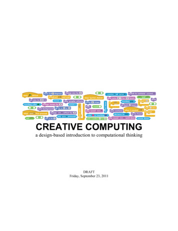
Chapter 5: Using digital PinsTo make a soft prototype with LEDswe need:As explained in chapter 2 the digital pins on the Arduino have onlytwo modes, either they are On or Off. The actual command forthese two states of the Arduino are 1 for on or 0 for off and thatis why we call theme digital pins. Normally we use the constantsHIGH and LOW since this makes it easier to read code comparedto using 0 and 1. Remember that the digital pin always gives theoutput power of 5V when high and 0V when LOW. Don’t connectanything straight to the digital pin if you don’t know that it canhandle 5V. Some conductive threadOne LEDOne 220 Ω resistorNon-conductive fabricPart 1: Soft prototyping with LEDs Sewing a LEDThis drawing illustrates how to sew your circuit on a piece of fabric.You can use any piece of fabric as long as it is not conductive:37
In this example we have made circles on the legs of the resistor andboth circles and squares of the legs on the LED. This isn’t only forcosmetic reasons, it’s also practical - it makes it easier to sew thecomponents in place and the different shapes is also good for keeping track of the long and short leg of the LED. For the voltage andground connection we have used cables, sewn in place with conductive thread. This is a good technique to use while testing yourprototype and in final prototypes is recommended that you sewyour Arduino board on to the fabric and make straight connectionswith conductive threa
Arduino The Arduino is an open source micro controller board used for electronic prototyping. The Arduino can receive data from sensors used to collect information in its soundings and it can be used to control other electronic components as lights, motors and more. Ther