Transcription
Parametric Modeling withAutodesk Fusion 360 First EditionRandy H. ShihSDCP U B L I C AT I O N SBetter Textbooks. Lower Prices.www.SDCpublications.com
Visit the following websites to learn more about this book:Powered by TCPDF (www.tcpdf.org)
2-1Chapter 2Parametric Modeling Fundamentals Create Simple Extruded Solid Models Understand the Basic ParametricModeling Procedure Create 2-D Sketches Understand the “Shape before Size”Design Approach Use the Dynamic Viewing Commands Create and Edit Parametric Dimensions
2-2Parametric Modeling with Autodesk Fusion 360IntroductionThe feature-based parametric modeling technique enables the designer to incorporatethe original design intent into the construction of the model. The word parametric meansthe geometric definitions of the design, such as dimensions, can be varied at any time inthe design process. Parametric modeling is accomplished by identifying and creating thekey features of the design with the aid of computer software. The design variables,described in the sketches as parametric relations, can then be used to quicklymodify/update the design.In Autodesk Fusion 360, the parametric part modeling process involves the followingsteps:1. Create a rough two-dimensional sketch of the basic shape of the base featureof the design.2. Apply/modify constraints and dimensions to the two-dimensional sketch.3. Extrude, revolve, or sweep the parametric two-dimensional sketch to createthe base solid feature of the design.4. Add additional parametric features by identifying feature relations andcomplete the design.5. Perform analyses on the computer model and refine the design as needed.6. Create the desired drawing views to document the design.The approach of creating two-dimensional sketches of the three-dimensional features isan effective way to construct solid models. Many designs are in fact the same shape inone direction. Computer input and output devices we use today are largely twodimensional in nature, which makes this modeling technique quite practical. This methodalso conforms to the design process that helps the designer with conceptual design alongwith the capability to capture the design intent. Most engineers and designers can relateto the experience of making rough sketches on restaurant napkins to convey conceptualdesign ideas. Autodesk Fusion 360 provides many powerful modeling and design-tools,and there are many different approaches to accomplishing modeling tasks. The basicprinciple of feature-based modeling is to build models by adding simple features one ata time. In this chapter, the general parametric part modeling procedure is illustrated; avery simple solid model with extruded features is used to introduce the Autodesk Fusion360 user interface. The display viewing functions and the basic two-dimensionalsketching tools are also demonstrated.
Parametric Modeling Fundamentals2-3The Adjuster DesignStarting Autodesk Fusion 3601. Select the Autodesk Fusion 360 option on the Start menu or select theAutodesk Fusion 360 icon on the desktop to start Autodesk Fusion 360. TheAutodesk Fusion 360 log in window will appear on the screen.2. In the Sign In dialog box, log inwith your email or username.
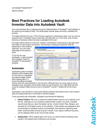
2-4Parametric Modeling with Autodesk Fusion 360The Autodesk Fusion 360 Screen LayoutThe default Autodesk Fusion 360 drawing screen contains the Quick access toolbar, theModeling toolbar, the Navigation toolbar, the Model Browser, the drawing area, and theView Cube. You may resize the Autodesk Fusion 360 drawing window by clicking anddragging the edges of the window, or relocate the window by clicking and dragging thewindow title area.WorkspaceQuick Access ToolbarModeling ToolbarModel BrowserView CubeGraphicsWindowComments PanelNavigation BarTimeline Control Panel Autodesk Fusion 360 is anintegrated system that can beused to create parts, assembly,animation, simulation, CAM and2D drawings. By default, theModel WorkSpace is activatedas shown. Also note that the part units is setto inches as shown in the upperleft corner of the AutodeskFusion 360 window.
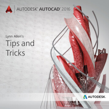
Parametric Modeling Fundamentals2-5Sketch Plane – It is an XY monitor, but an XYZ WorldDesign modeling software is becoming morepowerful and user friendly, yet the system stilldoes only what the user tells it to do. Whenusing a geometric modeler, we therefore needto have a good understanding of what itsinherent limitations are.In most 3D geometric modelers, 3D objectsare located and defined in what is usuallycalled world space or global space. Althougha number of different coordinate systems canbe used to create and manipulate objects in a3D modeling system, the objects are typicallydefined and stored using the world space. Theworld space is usually a 3D Cartesiancoordinate system that the user cannot changeor manipulate.In engineering designs, models can be very complex, and it would be tedious andconfusing if only the world coordinate system were available. Practical 3D modelingsystems allow the user to define Local Coordinate Systems (LCS) or User CoordinateSystems (UCS) relative to the world coordinate system. Once a local coordinate systemis defined, we can then create geometry in terms of this more convenient system.Although objects are created and stored in 3D space coordinates, most of the geometricentities can be referenced using 2D Cartesian coordinate systems. Typical input devicessuch as a mouse or digitizer are two-dimensional by nature; the movement of the inputdevice is interpreted by the system in a planar sense. The same limitation is true ofcommon output devices, such as CRT displays and plotters. The modeling softwareperforms a series of three-dimensional to two-dimensional transformations to correctlyproject 3D objects onto the 2D display plane.The Autodesk Fusion 360 sketching plane is a special construction approach that enablesthe planar nature of the 2D input devices to be directly mapped into the 3D coordinatesystem. The sketching plane is a local coordinate system that can be aligned to anexisting face of a part, or a reference plane.Think of the sketching plane as the surface on which we can sketch the 2D sections of theparts. It is similar to a piece of paper, a white board, or a chalkboard that can be attachedto any planar surface. The first sketch we create is usually drawn on one of theestablished datum planes. Subsequent sketches/features can then be created on sketchingplanes that are aligned to existing planar faces of the solid part or datum planes.
2-6Parametric Modeling with Autodesk Fusion 3601. Activate the Create Sketch icon with asingle click of the left-mouse-button.2. Move the cursor over the right vertical plane, the XY Plane, in the graphicsarea. When the XY Plane is highlighted, click once with the left-mouse-buttonto select the Plane as the sketching plane for the new sketch. The sketching plane is a reference location where two-dimensional sketches arecreated. Note that the sketching plane can be any planar part surface or datumplane.3. Click and press on the Sketch tab inthe main Ribbon area to display theavailable sketching tools as shown.Also note the Sketch Palette panel isalso activated with additionalsketching options.
Parametric Modeling Fundamentals2-7Creating Rough SketchesQuite often during the early design stage, the shape of a design may not have any precisedimensions. Most conventional CAD systems require the user to input the precise lengthsand locations of all geometric entities defining the design, which are not available duringthe early design stage. With parametric modeling, we can use the computer to elaborateand formulate the design idea further during the initial design stage. With AutodeskFusion 360, we can use the computer as an electronic sketchpad to help us concentrate onthe formulation of forms and shapes for the design. This approach is the main advantageof parametric modeling over conventional solid-modeling techniques.As the name implies, a rough sketch is not precise at all. When sketching, we simplysketch the geometry so that it closely resembles the desired shape. Precise scale orlengths are not needed. Autodesk Fusion 360 provides many tools to assist us infinalizing sketches. For example, geometric entities such as horizontal and vertical linesare set automatically. However, if the rough sketches are poor, it will require much morework to generate the desired parametric sketches. Here are some general guidelines forcreating sketches in Autodesk Fusion 360: Create a sketch that is proportional to the desired shape. Concentrate on theshapes and forms of the design. Keep the sketches simple. Leave out small geometry features such as fillets, roundsand chamfers. They can easily be placed using the Fillet and Chamfer commandsafter the parametric sketches have been established. Exaggerate the geometric features of the desired shape. For example, if thedesired angle is 85 degrees, create an angle that is 50 or 60 degrees. Otherwise,Autodesk Fusion 360 might assume the intended angle to be a 90-degree angle. Draw the geometry so that it does not overlap. The geometry should eventuallyform a closed region. Self-intersecting geometry shapes are not allowed. The sketched geometric entities should form a closed region. To create a solidfeature, such as an extruded solid, a closed region is required so that the extrudedsolid forms a 3D volume. Note: The concepts and principles involved in parametric modeling are verydifferent, and sometimes they are totally opposite, to those of conventional computeraided drafting. In order to understand and fully utilize Autodesk Fusion 360’sfunctionality, it will be helpful to take a Zen approach to learning the topics presentedin this text: Have an open mind and temporarily forget your experiences usingconventional Computer Aided Drafting systems.
2-8Parametric Modeling with Autodesk Fusion 360Step 1: Creating a Rough Sketch The Sketch toolbar provides tools for creating the basic geometry that can be usedto create features and parts.1. Move the graphics cursor tothe Line icon in the Sketchtoolbar. A Help-tip boxappears next to the cursorand a brief description of thecommand is displayed at thebottom of the drawingscreen: “Creates lines andarcs.”2. Select the icon by clicking once with the left-mouse-button; this will activate theLine command. Autodesk Fusion 360 expects us to identify the starting locationof a straight line.Graphics Cursors Notice a crosshair cursor is shown when graphical input is expected.1. Left-click a starting point for the shape, roughly just below the center of thegraphics window.2. As you move the graphics cursor, you will see a digital readout next to the cursorand also in the Status Bar area at the bottom of the window. The readout givesyou the cursor location, the line length, and the angle of the line measured fromhorizontal. Move the cursor around and you will notice different symbols appearat different locations.
Parametric Modeling Fundamentals2-93. Move the graphics cursor toward the right side of the graphics window and createa horizontal line as shown below (Point 2). Notice the geometric constraintsymbol, a short horizontal line indicating the geometric property, is displayed.ConstraintSymbolPoint 1Point 2Geometric Constraint SymbolsAutodesk Fusion 360 displays different visual clues, or symbols, to show you alignments,perpendicularities, tangencies, etc. These constraints are used to capture the design intentby creating constraints where they are recognized. Autodesk Fusion 360 displays thegoverning geometric rules as models are built. To prevent constraints from forming, holddown the [Ctrl] key while creating an individual sketch curve. For example, whilesketching line segments with the Line command, endpoints are joined with a Coincidentconstraint, but when the [Ctrl] key is pressed and held, the inferred constraint will not becreated.Verticalindicates a line is verticalHorizontalindicates a line is horizontalDashed lineindicates the alignment is to the center point orendpoint of an entityParallelindicates a line is parallel to other entitiesPerpendicularindicates a line is perpendicular to other entitiesCoincidentindicates the cursor is at the endpoint of an entityConcentricindicates the cursor is at the center of an entityTangentindicates the cursor is at tangency points to curves
2-10Parametric Modeling with Autodesk Fusion 3601. Complete the sketch as shown below, creating a closed region ending at thestarting point (Point 1). Do not be overly concerned with the actual size of thesketch. Note that all line segments are sketched horizontally or vertically.Point 6Point 5Point 4Point 1Point 3Point 22. Inside the graphics window, click oncewith the right-mouse-button todisplay the option menu. Select [OK]in the pop-up menu, or hit the [Esc]key once to end the Sketch Linecommand.Step 2: Apply/Modify Constraints and Dimensions As the sketch is made, Autodesk Fusion 360 automatically applies some of thegeometric constraints (such as horizontal, parallel, and perpendicular) to the sketchedgeometry. We can continue to modify the geometry, apply additional constraints,and/or define the size of the existing geometry. In this example, we will illustrateadding dimensions to describe the sketched entities.1. In the sketch toolbar, select theSketch Dimension commandas shown. The SketchDimension command isgenerally known as SmartDimensioning in parametricmodeling.
Parametric Modeling Fundamentals2-112. The message “Select Geometry to Dimension” is displayed in the Status Bar areaat the bottom of the Fusion 360 window. Select the bottom horizontal line by leftclicking once on the line.2. Pick the bottom horizontalline as the geometry todimension.3. Pick a location belowthe line to place thedimension.3. Move the graphics cursor below the selected line and left-click to place thedimension. (Note that the value displayed on your screen might be different thanwhat is shown in the figure above.)4. Accept the default value by hitting the Enter key once. The Sketch Dimension command will create a lengthdimension if a single line is selected.5. Select the top-horizontal line as shown inthe figure.6. Select the bottom-horizontal line asthe second entity to dimension asshown.
2-12Parametric Modeling with Autodesk Fusion 3607. Pick a location to the left of the sketch to place the dimension.8. Accept the default value by hitting the Enter key once. When two parallel lines are selected, the Sketch Dimension command will create adimension measuring the distance between them.9. On your own, repeat the above steps and create additional dimensions (acceptingthe default values created by Fusion 360) so that the sketch appears as shown. Hitthe [ESC] key once to end the Dimension command before proceeding to the nextpage.
Parametric Modeling Fundamentals2-13Dynamic Viewing Functions – Zoom and Pan Autodesk Fusion 360 provides a special user interface called Dynamic Viewing thatenables convenient viewing of the entities in the graphics window.1. Click on the Zoom Window icon located in the Navigation bar as shown.2. Move the cursor near the center of the graphics window.3. Inside the graphics window, press and hold down the left-mouse-button, thenmove downward to enlarge the current display scale factor.4. Press the [Esc] key once to exit the Zoom command.5. Click on the Pan icon located next to the Zoom command in the Navigation bar.The icon is the picture of a hand. The Pan command enables us to move the view to a different position. This functionacts as if you are using a video camera.6. On your own, use the Zoom and Pan options to reposition the sketch near thecenter of the screen.Modifying the Dimensions of the Sketch1. Select the dimension that is at thebottom of the sketch by doubleclicking on the dimension text.1. Select this dimensionto modify.
2-14Parametric Modeling with Autodesk Fusion 3602. In the Edit Dimension window, thecurrent length of the line is displayed.Enter 2.5 to set the length of the line.3. Hit on the Enter key once to acceptthe entered value. Autodesk Fusion 360 will now update the profile with the new dimension value.4. On your own, repeat the abovesteps and adjust thedimensions so that the sketchappears as shown.5. In the Ribbon toolbar, click once with the leftmouse-button on Stop Sketch to end theSketch option.Step 3: Completing the Base Solid FeatureNow that the 2D sketch is completed, we will proceed to the next step: create a 3D partfrom the 2D profile. Extruding a 2D profile is one of the common methods that can beused to create 3D parts. We can extrude planar faces along a path. We can also specify aheight value and a tapered angle. In Autodesk Fusion 360, each face has a positive sideand a negative side; the current face we're working on is set as the default positive side.This positive side identifies the positive extrusion direction and it is referred to as theface's normal.
Parametric Modeling Fundamentals2-151. In the Create toolbar, select the Extrude commandby clicking the left-mouse-button on the icon asshown.2. Select the 2D sketch we just created by clicking on the closed region as shown.3. In the Extrude edit box, enter 2.5 as the extrusion distance.4. Click the OK button to proceed with creating the3D part. Note that all dimensions disappeared from thescreen. All parametric definitions are stored in thedatabase and can be re-displayed.
2-16Parametric Modeling with Autodesk Fusion 360Dynamic Rotation of the 3D Object – Free OrbitThe Free Orbit command allows us to: Orbit a part or assembly in the graphics window. Rotation can be around thecenter mark, free in all directions, or around the X/Y-axes in the 3D-Orbitdisplay. Reposition the part or assembly in the graphics window. Display isometric or standard orthographic views of a part or assembly.The Free Orbit tool is accessible while other tools are active. Autodesk Fusion 360remembers the last used mode when you exit the Orbit command.1. Click on the Free Orbit icon in theNavigation bar. The 3D Orbit display is a circular rim with four handles and a center mark. 3D Orbitenables us to manipulate the view of 3D objects by clicking and dragging with theleft-mouse-button:Handle Drag with the left-mousebutton near the center for freerotation. Drag on the handles to orbitaround the horizontal orvertical axes. Drag on the rim to orbitabout an axis that isperpendicular to thedisplayed view. Single left-click to align thecenter mark of the view.Center MarkCircular Rim2. Inside the circular rim, press down the left-mouse-button and drag in an arbitrarydirection; the 3D Orbit command allows us to freely orbit the solid model.3. Move the cursor near the circular rim and notice the cursor symbol changes to asingle circle. Drag with the left-mouse-button to orbit about an axis that isperpendicular to the displayed view.
Parametric Modeling Fundamentals2-174. Single left-click near the top-handle to align the selected location to the centermark in the graphics window.5. Activate the Constrained Orbit option by clicking on the associated icon asshown. The Constrained Orbit can be used to rotate the model about axes in Model Space,equivalent to moving the eye position about the model in latitude and longitude.6. On your own, use the different options described in the above steps andfamiliarize yourself with both of the 3D Orbit commands. Reset the displayroughly to the Isometric angle before continuing to the next section. Note that while in the 3D Orbit mode, a horizontal marker will be displayed nextto the cursor if the cursor is away from the circular rim. This is the exit marker.Left-clicking once will allow you to exit the 3D Orbit command.Exit marker
2-18Parametric Modeling with Autodesk Fusion 360Dynamic Viewing - Quick KeysWe can also use the mouse and the keyboard to access the Dynamic Viewing functions.Below are the default Autodesk Fusion 360 quick keys settings; we can use other settingsif preferred. Panning – Press and drag with the mouse wheelPressing and dragging with the mouse wheel can also reposition the display. Thisallows you to reposition the display while maintaining the same scale factor of thedisplay.PanMOUSE WHEEL: PRESS & DRAG Zooming – Turning the mouse wheelTurning the mouse wheel can also adjust the scale of the display. Turning forwardwill reduce the scale of the display, making the entities display smaller on thescreen. Turning backward will magnify the scale of the display.ZoomMOUSE WHEEL: TURNING 3D Rotation – Shift and the middle-mouse-buttonHold the Shift key down and drag with the middle-mouse-button to orbit thedisplay.3D RotationShift MOUSE
Parametric Modeling Fundamentals2-19Viewing Tools – Navigation bar and View CubeDisplay SettingsPanFit/Zoom AllConstrained OrbitFree OrbitZoomZoom WindowViewportsLook AtGrid and SnapsOrbit – In a part or assembly, adds an orbit symbol and cursor to the view. You can orbitthe view planar to the screen around the center mark, around a horizontal or vertical axis,or around the X and Y axes.Look At – In a part or assembly, zooms and orbits the model to display the selectedelement planar to the screen or a selected edge or line horizontal to the screen. (Not usedin drawings.)Fit/Zoom All – Adjusts the view so that all items on the screen fit inside the graphicswindow.Zoom Window – Use the cursor to define a region for the view; the defined region iszoomed to fill the graphics window.Zoom – Moving upward will reduce the scale of the display, making the entities displaysmaller on the screen. Moving downward will magnify the scale of the display.Pan – This allows you to reposition the display while maintaining the same scale factorof the display.Display settings – This panel contains multiple control to the display related settings,such as Visual Style and Camera.View CubeView Cube – The View Cube is a 3D navigation tool that appears atthe upper right corner of the Fusion 360 main window. The ViewCube is a clickable interface which allows you to switch betweenstandard and isometric views.
2-20Parametric Modeling with Autodesk Fusion 360The View Cube also provides visual feedback about the current viewpoint of the modelas view changes occur. When the cursor is positioned over the View Cube, it becomesactive and allows you to switch to one of the available preset views, roll the current view,or change to the Home view of the model.1. Move the cursor over the ViewCube and notice the different sidesof the ViewCube become highlighted and can be activated.2. Single left-click when the front side is activated as shown. Thecurrent view is set to view the front side.3. Move the cursor over the counter-clockwise arrow of theViewCube and notice the orbit option becomes highlighted.4. Single left-click to activate the counter-clockwise option asshown. The current view is orbited 90 degrees; we are stillviewing the front side.5. Move the cursor over the left arrow of the ViewCube and noticethe orbit option becomes highlighted.6. Single left-click to activate the left arrow option as shown. Thecurrent view is now set to view the top side.7. Move the cursor over the top edge of the ViewCube and noticethe roll option becomes highlighted.8. Single left-click to activate the roll option as shown. The viewwill be adjusted to roll 45 degrees.9. Move the cursor over one of the corners of the ViewCube anddrag with the left-mouse-button to activate the Free Rotationoption.10. Move the cursor over the home icon of the ViewCube and noticethe Home View option becomes highlighted.11. Single left-click to activate the Home View option as shown.The view will be adjusted back to the default isometric view.
Parametric Modeling Fundamentals2-21Display Modes The Visual Style in the Display Settings list has six display-modes showing shadedrenderings and wireframe representations of the model. Shaded Solid:The Shaded Solid display mode generates ahigh quality shaded image of the 3D object. Wireframe Image:The Wireframe Image display option allows thedisplay of the 3D objects using the basicwireframe representation scheme.Orthographic vs. Perspective Besides the above basic display modes, we can also choose orthographic view usingthe parallel edges representation scheme or perspective view using the perspective,nonparallel edges, and representation scheme of the display. Click on the Camera listin the Display Settings to select the different display options as shown in the figure.
2-22Parametric Modeling with Autodesk Fusion 360Step 4-1: Adding an Extruded Feature1. In the Create toolbar, select theCreate Sketch command byleft-clicking once on the icon.2. Next to the cursor, the message “Select a plane or planar face” is displayed.Autodesk Fusion 360 expects us to identify a planar surface where the 2D sketchof the next feature is to be created. Move the graphics cursor on the 3D part andnotice that Autodesk Fusion 360 will automatically highlight feasible planes andsurfaces as the cursor is on top of the different surfaces. Pick the top horizontalface of the 3D solid object.2. Pick the top face ofthe solid model. Note that the sketch plane is aligned tothe selected face. Autodesk Fusion 360automatically establishes a UserCoordinate-System (UCS) and records itslocation with respect to the part on whichit was created. Next, we will create and profile another sketch, a rectangle, which will be used tocreate another extrusion feature that will be added to the existing solid object.3. Select the Line command by clicking oncewith the left-mouse-button on the icon in theSketch tab on the Ribbon.
Parametric Modeling Fundamentals2-234. Create a sketch, starting at the top left corner of the solid model, with five linesegments perpendicular/parallel to the solid model as shown below.5. Inside the graphics window, click once with theright-mouse-button to display the option menu.Select Cancel (ESC) in the pop-up menu to endthe Line command.6. Select the Sketch Dimension command in the Sketchtoolbar. The Sketch Dimension command allows us toquickly create and modify dimensions. You can also hit[D] on the keyboard to activate this command.7. Create the four size dimensions, set values to 2.5 & .75, to describe the size of thesketch as shown.
2-24Parametric Modeling with Autodesk Fusion 3608. Inside the graphics window, click once with the rightmouse-button to display the option menu. Select OK inthe pop-up menu to end the Sketch Dimensioncommand.9. In the Ribbon area, select Stop Sketch to end theSketch command.10. In the Create toolbar, select the Extrude commandby left-clicking on the icon.11. Select inside the 2D sketch we just created as the region to extrude.12. Move the cursor on top of the arrow; notice thedashed line appears as shown. We can drag the arrow,with the left mouse button, to set the extrusiondistance and direction.
Parametric Modeling Fundamentals13. Drag the arrow downward, with the left mouse button, and set the extrusiondistance to -2.5 as shown.14. In the Extrude pop-up window, confirm thesettings are as shown.15. Click on the OK button to proceed withcreating the extruded feature.2-25
2-26Parametric Modeling with Autodesk Fusion 360Step 4-2: Adding a Cut Feature Next, we will create and profile a circle, which will be used to create a cut feature thatwill be added to the existing solid object.1. In the Create toolbar, select theCreate Sketch command byleft-clicking once on the icon.2. Pick the top horizontal face of the 3D solidmodel as shown. Note that the sketch plane is aligned to theselected face. Autodesk Fusion 360automatically establishes a User-CoordinateSystem (UCS) and records its location withrespect to the part on which it was created.3. Select the Center Diameter circlecommand by clicking once with the leftmouse-button on the icon in the Sketchtoolbar as shown.4. Create a circle of arbitrary size onthe top face of the solid model asshown.
Parametric Modeling Fundamentals2-275. On your own, create and modify the dimensions of the sketch as shown in thefigure.6. Inside the graphics window, click once with the rightmouse-button to display the option menu. SelectCancel in the pop-up menu to end the SketchDimension command.7. Inside the graphics window, click once with the rightmouse-button to display the option menu. SelectFinish 2D Sketch in the pop-up menu to end theSketch option.8. In the Create toolbar, select the Extrude commandby left-clicking on the icon.9. In the Extrude pop-up control, the Profile button ispressed down; Autodesk Fusion 360 expects us toidentify the profile to be extruded.
2-28Parametric Modeling with Autodesk Fusion 36010. Click on the inside of the sketchedcircle to define the extrude profileas shown.11. Select the CUT option in the feature optionlist to set the extrusion operation to Cut.12. Move the cursor on top of the arrow;notice the dashed line appears.13. Drag the arrow downward, with theleft mouse button, to set theextrusion direction.14. Set the Extent option to Through All asshown. The All option instructs thesoftware to calculate the extrusion distanceand assures the created feature will alwayscut through the full length of the model.
Parametric Modeling Fundamentals2-2915. Click on the OK button to proceed with creatingthe extruded feature.Step 4-3: Adding another Cut Feature Next, we will create and profile a triangle, which will be used to create a cut featurethat will be added to the existing solid object.1. In the 3D Model tab select the CreateSketch command by left-clicking onceon the icon.2. Pick the vertical face of the 3D solidmodel next to the horizontal section asshown.
2-30Parametric Modeling with Autodesk Fusion 3603. Select the Line command by clicking oncewith the left-mouse-button on the icon in theSketch tab.4. Start at the upper left corner and creat
Fusion 360, we can use the computer as an electronic sketchpad to help us concentrate on the formulation of forms and shapes for the design. This approach is the main advantage of parametric modeling over conventional solid-modeling techniques. As the name implies, a roug