Transcription
Recent structural interventions to the eighteenthcentury Greatham Bridge, UK.Pasquale Ponterosso1University of Portsmouth, School of Civil Engineering and Surveying, Portland Building,PO1 3AH, Portsmouth, UK1Corresponding author. Email: Pasquale.ponterosso@port.ac.ukABSTRACTThis paper describes interventions carried out on Greatham Bridge, a road traffic bridgespanning the River Arun in the county of West Sussex (UK) which is also a scheduled ancienthistoric monument. It carries a B road used by traffic traversing to or from the A29 and A283and for traffic exploring the local countryside. The first intervention described in this paperoccurred in 2002 and the second in 2018. Although a listed monument it is also a live part ofthe road traffic infrastructure network in the region. The paper details the challenges involvedin working on an ancient protected structure in an area of restricted access and of ecologicalimportance. The differences and improvements in processes and procedures between 2002 and2018 are highlighted.1.IntroductionWest Sussex County Council (WSCC) is the local government authority tasked with the dutyof the maintenance and upkeep of all road traffic bridges within its area (excludingMotorways). This includes old and ancient bridges. Within the area are approximately 720highway bridges and 90 footbridges. Of this bridge stock 3-400 are older than circa 1900 andthis includes 10 bridges designated as ancient monuments. Any works carried out on thesemonuments must meet the exacting requirements of Historic England (a public body whichwas previously part of English Heritage). This means that any works carried out must notsignificantly alter the appearance and, furthermore, all works must be scrupulously recorded ingreat detail.WSCC’s bridge inspection regime is currently the same for all bridges regardless of age orusage. It consists of an inspection every 22 months. There are two general inspectionsfollowed by a more detailed principal inspection (i.e. every 66 months).2.History and ConstructionGreatham Bridge is a medieval bridge commissioned by Sir Henry Tregoz (of the Manor ofGreatham) most probably completed in 1294 (see http://www.westsussex.info/greathambridge.shtml). The bridge is located in the Horsham District of the county of West Sussex,England (at OS grid reference TQ043159).The bridge is a multiple span masonry arch causeway leading to a two span wrought iron latticegirder supported bridge. The western end masonry arch causeway comprises 8 low elliptical
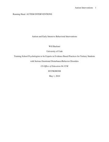
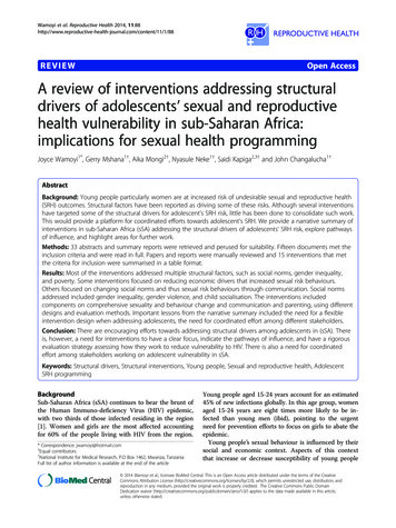
stone arches and 2 higher arches, all interspaced with cutwaters. The higher arches adjoin themore modern part of the bridge. To the east is a solid ramp. The wrought iron lattice girderssupport transverse iron plates on which a concrete deck is seated. The girders are supportedon a central steel trestle pier at mid-span. The bridge carries a single carriageway with apermitted traffic speed of 60mph over the River Arun with a weight restriction of 7.5 tonnes.The bridge was originally built in 1294 and completely reconstructed in 1795-99 in stonearches. In 1838 part of the bridge was destroyed by a flood and a wooden bridge wasconstructed over the main part of the river. The wooden bridge lasted 30 years and wasreplaced by the lattice girder bridge in 1869. The information available concerning thetechnical specifications and history of the bridge are held in the county’s bridge records.However, the details become increasingly less complete as they stretch back in time. There isvery little detailed information from before circa 1900. The central pier was added circa 1912.Additional steel stiffeners and the concrete deck were added in 1942 to enable Class 40 militaryvehicles to use the crossing. The structural type of the bridge is a continuous two span latticethrough girder with stiffeners providing U frame restraint. The central piers are column pilesembedded in concrete. The span arrangement is two equal spans of 9.92m (19.8m total span)and the lattice girders also act as parapets (together with high upstand kerbs). Photographs ofthe bridge as it appeared in 2002 (prior to the strengthening works to be described) are shownin figures 1-3. The addition of the central supporting pier meant the introduction of a stressreversal because the bridge had been originally designed as a simply supported single spanstructure.Fig 1 View of Greatham Bridge from South West prior to works being carried out.
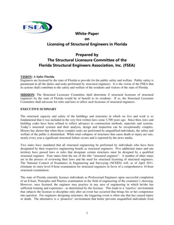
Fig 2 View of Greatham Bridge from South East prior to works being carried out. Showingcentral temporary stiffeners added.Fig 3 Drawing of South elevation of Greatham Bridge3.Structure Condition (2002)The bridge was inspected and assessed in 1995. The masonry arches passed the 40 tonnesassessment live loading, as did the central trestle pier. The transverse girders, lateral support,deck plate and connections (rivets) were all found to be adequate only for 7.5 tonnes assessmentlive loading. However, the lattice trusses were considered to have zero assessment live loading.The bridge was originally designed with a single span (the lattice members having larger crosssection at each end to resist shear forces at the original support points). The addition of thecentral trestle pier transformed the bridge into a two span structure, continuous over the centrepier (thereby altering the bending moment profile, inducing hogging at the centre of the bridgeas opposed to sagging etc.). The installation of the centre pier resulted in an increase in theload taken by these central web members. The failure mode was found to be buckling of thelattice web members in the vicinity of the intermediate pier.4.InterventionAfter the assessment, the Client, West Sussex County Council (WSCC) was obliged to act.The choices available were to strengthen the existing bridge or to demolish and rebuild anew.The option of demolition and replacement was discounted due to cost and probable EnglishHeritage objection. Several alternative strengthening schemes were discussed with EnglishHeritage and the Client most of which were discounted on the basis of visual appearance andcost of works which left the final selected scheme. The strengthening works proposed were tothe superstructure of the lattice girder and to the concrete deck. Essentially the schemeconsisted of replacing many of the lattice members with larger (in cross-sectional area),stronger members to increase the overall strength of the girder. In the centre of each girder(directly above the central supporting pier) new central stiffener plates would be designed andplaced, see figure 4. This increase in girder strength would be supplemented by thereplacement of the original concrete deck with a lighter, “voided” reinforced concrete deck.The deck would be formed with void spaces between it and the deck plate such that theconcrete’s weight would be supported by the transverse beams close to the points at which theyjoined the main longitudinal girders, see figure 5. Due to the demands of the local watercompany, it was also necessary to include in the design a new larger diameter water duct. In
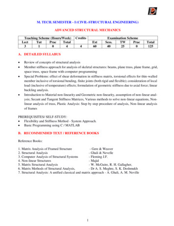
the existing bridge, there was a 100mm diameter water main. This was to be replaced with a125mm water main within a 220mm water ductFig 4 New design of central stiffening plate
Fig 5 Drawing of previous deck profile and new voided deck slab profile5.Strengthening DesignThe wrought iron lattice girder was analysed as a two-span plane truss using LEAP 5 (LinearElastic Analysis Program) Version 6.1. The concrete deck slab was analysed as a finite elementslab with elastic supports modelling the support from the main girders and cross girders. Foranalysis and design, the articulation arrangements of the bridge were assumed to be freedomof rotation at all support locations. The deck was assumed to accommodate thermal movementsabout the centre support with end supports being free to slide over padstone bearings.The design criteria used were for HA loading to 7.5 tonnes as per BD 21/01 assuming Lgconditions (Low HGV flow and good surface state) and for footbridge live loading to BD
37/01. BD 21/01 was the UK standard for the “Assessment of Highways Bridges andStructures” and was written by the Bridges Engineering Division of the UK’s Department forTransport. BD 37/01 “Loads for Highway Bridges” was the standard that specifies the loadingto use for the design of highway bridges and associated structures. This standard specifies HAloading as that design loading which adequately covers the effects of all permitted normalvehicles (i.e. not abnormal indivisible loads) found on roads in the UK. It consists of auniformly distributed load and a knife-edge load (across the carriageway). Both BD 21/01 and37/01 were volumes within the UK “Design Manual for Roads and Bridges”. The categorytwo check of the deck calculations was carried out by analysing the deck as a grillage (againusing LEAP 5). Reinforced concrete (RC) detailing was carried out with the SAM (Sectionsand Moments) software package, based on the analysis of a finite width strip of transversespanning slab. This was fed back into the grillage model using the worst transverse andlongitudinal bending moments to check the longitudinal and transverse “beam” sectionreinforcement designs. The deck and RC edge beam were assessed for accidental wheel load(AWL), moment and shear resistance. AWL is another loading arrangement (from BD 37/01),which represents the possibility of vehicular loading passing off the nominal carriageway andonto outer verges or footways. It was not necessary to check for HB loading (exceptionalindustrial loads such as generators, transformers, machine presses and so on) because of thenarrow breadth of the bridge and because it is a plated structure. Checks were completed forearly thermal cracking, as per BD 28/87 (another standard within the “Design Manual forRoads and Bridges”). Checks were also carried out to ensure the standard requirements forminimum areas of main and secondary reinforcement were satisfied.6.Strengthening WorksThis project presented the designers, based at the (then) local Halcrow Group offices, severalchallenges over and above the normal design requirements. The bridge is in a designated Siteof Special Scientific Interest (SSSI), it is also listed as a Scheduled Monument (CountyMonument No. 140) and is immediately adjacent to the grounds of a private angling club onone bank and a wildlife reserve on the other. Further to these issues, the river directlydownstream of the bridge is home to one of (at the time) only three colonies of Depressed RiverMussels in the UK. These creatures are very rare and very sensitive to environmental changes.This fauna was protected under the UK’s Habitat’s Directive and their wellbeing wasconsidered, by the Environment Agency (EA), to be of prime importance.A selection of contractors from the council’s select list were contacted (to determine theirinterest in carrying out the works) and documents were issued for tender to 4 of them. The besttender was for the value of 98,000 by Dean & Dyball Construction Ltd, who were dulyselected. After consultation with English heritage, the Environment Agency and theContractor, the agreed start date for the works was the 25th February 2002 and the plannedduration of the Works was 11 weeks.6.1 Deck
The removal of the concrete deck took longer than anticipated by the Contractor. The concretewas stronger than expected and the transverse girders within the concrete were very effectivelywelded in place, see figure 6.Fig 6 Original concrete deck being broken outOnce the concrete deck had been completely removed, it was noticed that the abutment supportwas not as stiff as originally assumed. Standing on the bare plate deck, midway between thecorners of the deck at each end it was possible to feel the movement quite easily. The endbeam design was checked with this new knowledge in mind and a redesign was necessary whilethe works were in progress, resulting in extra steel being added to each end beam to increasetheir strength.Once the old deck slab had been broken out, the wrought iron deck plate was inspected forsigns of corrosion and there were very little. The plate was remarkably clean and intact. Beforeplacing the polystyrene deck void former panels, 6 drainage holes were drilled through the13mm plate and fitted with 50mm long 20mm diameter drainage pipes which were epoxiedinto place, flush with the top of the plate (see figure 7). The later 2018 refurbishment was onlyto the masonry arch elements of the bridge after inspections revealed their poor condition.During these works, no inspection was made of the iron deck plate. However, the deck platehas been inspected in other regular inspections and has not suffered any great deterioration.
Fig 7 Deck plate drainage detailsIt was decided to locate the new water main duct within the new southern edge beam/kerb. Theduct was rather large (as per the requirements of the water company) and this did cause anelement of congestion with the steel in the edge beam, see figure 8. Before each pour checkshad to be carried out for adequate clearance between the steel and the duct.
Fig 8 Southern edge beam showing replacement water ductThe new concrete deck was grade 50N/mm2 concrete with Grade 460N/mm2 steel, type 2deformed bars to BS 4449. The concrete deck was constructed in two pours. One pour to formthe edge beams, and the subsequent pour to form the deck itself. The deck void was createdby pouring over the top of polystyrene former panels. Once any concrete had been cast, nofurther work was permitted on the deck during the first 24 hours of the cure that could havevibrated the placed concrete.The formwork itself was the cause of a delay in the program as the Contractor hadunderestimated the complexity of it. The outside formed face of each of the edge beamspartially covered the foot of the lattice members. The formwork had to be cut to accommodatethis irregular pattern of bars. The operation took several days longer than the Contractor hadprogrammed for. It was impossible to “chute” the concrete due to the weight restriction of thebridge and the Contractor decided that it would be cheaper to pump than to use a crane andskip. After sufficient setting time the deck was waterproofed. The road surfacing operationwas done by hand with no heavy plant on the bridge at allOriginally it had been assumed that after the works had been substantially completed therewould be a fairly small amount of painting required, to protect any scratched or damagedsteel/iron surfaces. These defects would be where scaffolding supports had been pressingagainst original ironwork for instance. However, after a short while, it became clear that therewould be much more re-painting required than originally thought. It was decided that, as theaccess scaffolding was already in place and the Contractor on site, to re-paint the entire bridgeimmediately after the strengthening works. For EA approval for these re-painting operationsit was necessary to provide details of the existing paint system, its composition etc. and tospecify exactly how the existing paintwork would be prepared for re-painting. Fortuitously,the “original” paint specifications were found in the county bridge records. This would havebeen the colour and specification from 1942 when the bridge was strengthened to Class 40military standards. The works were carried out by a local coating contracting company, whichhad worked for the council before and had knowledge of environmental requirements in thearea. Despite that working knowledge, the contractor was, of course, briefed thoroughly in therequirements of the works to be conducted. All steel was provided with a full paint protectionsystem with a grey finishing coat. Thinner replacement lattice members (less than 6mm thick)had a galvanised metal coating under the paint system.Existing paint was cleaned off back to the bare metal, then a primer layer and undercoat layerwas applied. The top layer was a two-component, aliphatic polyurethane with a gloss “NaturalGrey” finish (Tikkurila 168 Temathane PLV). This is an extremely tough and durable systemwith exceptional weathering characteristics. It can be applied an infinite number of times overitself, and is suitable in marine environments. It was also an approved item by the UKHighways Agency (Item 168) for use on steel highways bridges. The pot life of this two-packsystem is 4 hours (after the parts are mixed). Onsite the painting contractors mixed one litre ata time and applied by hand (brush).
As for the preparation, high-pressure water washing as opposed to grit blasting, was suggestedand agreed upon. This required an increased environmental protection in the form of extra(double) sheeting (see figure 9) and the wet vacuuming of all arisings. Meetings between EArepresentatives, Fisheries Officers, Pollution Control Officers and the Contractor to discuss thematter resulted in the requirement (amongst others) that the washing operations be carried outon an outward tide. It took several (extra) weeks to gain approval for these operations.Fig 9 Extra (double) Sheeting During Repainting Operations6.2 Lattice GirderAs the lattice members were to be removed and replaced, there was a need to consider, in detail,the construction sequence (as each time a member is removed the strength of the girder isreduced). The analysis of the construction sequence had to take into account the effects of theremoval and replacement of pairs of lattice truss members, one at a time. It was found that thecritical phase of the strengthening would be the replacement of the central lattice members withthe new central stiffener plate (and adjacent members). It was necessary to apply temporarybracing to the structure during this phase. The loading due to temporary works (to besuspended from the bridge) during the construction phase also had to be considered during thedesign phase. In fact, the loading restrictions varied throughout the stages of the works. Thesetemporary works involved the placement of access scaffolding, and environmentally protectivedouble sheeting, completely around and suspended from the bridge, see figure 9. The accessscaffolding was slung around and under the bridge so that access was available to both sidesof each girder.The replacement lattice members, stiffeners and strengthening plates were fabricated by a localsteel fabrication company and were specified to be Grade Fe 430 Steel (tensile strength 430N/mm2 to 530 N/mm2). The specification was to to BS EN 10025. This British Standard setsout specifications for flat and long products of hot rolled structural steels. The steels coveredare normally used in welded, bolted and riveted structures. According to the structuralanalysis/design it was necessary to replace 40% (in number) of the lattice members. Themembers replaced were of cross sectional dimensions 63.5mm by 12.5 mm and 63.5mm by
9.5mm. They were replaced with members of dimensions 90mm by 30mm and 90mm by25mm.The mass of the new central support stiffener was 164kg and required a small crane to lift intoposition.A potential problem was found in the attachment of the new steel work to the existing trusswhere there were splices along the girder. The original truss was joined together using rivets.The fishplate’s rivet heads protruded from the face of the plate and would have obstructed theflush attachment of the new steel members. It would have been possible to either reduce thesection size of the new members near their ends or to pack out the new members (to bring theends away from the splices at the point of attachment. For ease of fabrication, it was decidedto choose the latter option and to also neck the ends of the new members (see figure 10).Fig 10 Splice plates and lattice member attachments to top flangeAs stated above, the original bridge connections were rivets. To maintain the appearance ofthe bridge, the use of Tension Control Bolts (TCBs) was specified in the strengthening works.These high strength friction grip bolts have rounded, rivet-like heads and are tightened usingspecial proprietary tools such that, at the correct tension, a spandrel on the end of the bolt shearsoff. The nut can then have a plastic cap fitted over it, which also gives a rivet-head likeappearance (particularly when over painted).7.Results of 2002 Strengthening WorksThe original estimate for the Works was 98,000. The tender for the works was 98,300. Thefinal cost of the Works was 102,700 and the time to completion was 19 weeks compared tothe 11 weeks agreed at the outset. However substantial completion took 14 weeks. Some ofthe increase in cost and time can be attributed to the fact that the contract was varied to allowfor the complete re-painting of the bridge after the strengthening works. This incurred a twoweek wait for an EA decision (regarding re-painting) and then another 3 weeks carrying outthe painting. Some of the delay/budget overrun was due to the fact that the removal of theoriginal concrete deck took longer than expected, the manufacturer of extra stiffeners (somehad been fabricated incorrectly “handed”) and other minor unforeseen factors. However,despite these challenges, the bridge was strengthened as planned, the environment was
unaffected and the immediately surrounding area retains all its original beauty and status as aSite of Special Scientific interest, see figure 11.The bridge was strengthened and upgraded sympathetically enough to be awarded acommendation at the ICE Historic Bridge and Infrastructure Awards (HBIA) in 2003. Judgescommented that it was “a very good repair, carried out extremely well” (NCE, 2003).Fig 11 Greatham Bridge in 2003 after strengthening works completed8.2018 Arch Refurbishment WorksThe 2018 masonry arch refurbishment followed the observation of significant areas of failing(eroded) stone work. Some of this is shown in figs 12 - 14. The refurbishment gave the councilthe opportunity to excavate into the top of the arches and make a true measurement of the ringdepth. This was necessary because an earlier analysis had suggested that the ring depth of thesearches was critical to the weight limit of the bridge. The measurement was carried out bytaking levels from above the top of the ring (after excavation of the road surface) and frombelow. It was found that the ring depth was 310mm rather than the initial assessment estimateof 300mm. Anything greater than 300mm gave the arches a 7.5 tonne rating. However, if thedepth had been below 300mm while the arch refurbishment work was going on it would havebeen possible to strengthen the arches at the same time. This would probably have beenaccomplished by excavating from above and constructing a lightweight concrete slab abovethe ring and then pinning the arch from below to the slab.Fig 12 Eroded stone work prior to 2018 refurbishment
Fig 13 Eroded stone work prior to 2018 refurbishmentFig 14 Eroded stone work prior to 2018 refurbishmentThe analysis of the arch strength was carried out by Parsons Brinckerhoff for WSCC and theConsultants for the refurbishment work were WSP, with Contractors Balfour Beatty.The original budget for the works was 300,000 but the final cost was only 200,742.17. Themain reason for this big difference was the eventual non-use of a temporary dam (see figure
15). Where work at, or below, the water line was necessary, the work was planned to becompleted while the river was held back by the hire of a temporary dam (at a cost of 90,000).It was originally planned to use the temporary dam system (to provide a dry work zone) torestrict flow through one or two arches at a time in order to minimise water flow restrictionunder the bridge i.e. staged work. In reality, the dam failed after 3 weeks and was thenabandoned as the contractor (rightly) refused to allow operatives to work behind it after itsfailure. This meant that the work was carried out only during low-water conditions. The RiverArun is still tidal at Greatham Bridge (in fact it is tidal for a length of 41km upstream from thesea at Littlehampton). Figure 16 shows the scaffolding arrangements required to give accessto the faces of the arches.Fig 15 Temporary dam used in the early stages of the refurbishmentFig 16 Refurbishment temporary works for access to arch facesMany masonry arch blocks had to be replaced to restore the integrity of this section of thebridge and figures 17-19 show some of the affected areas. These figures can be compared withfigures 9-11, prior to the refurbishment.
Prior to the refurbishment the existing arches were constructed using Salterwath Limestonebelow the waterline and Midhurst Sandstone above the water line. Local stone from a quarryvery close to the site (Fittleworth, Pulborough) was identified. The replacement stone closelymatched that of the existing structure in type, colour and texture. Sample stones were providedfor and approved by Historic England during early site meetings.The scope of the works involved the removal and replacement of severely deterioratedstonework and the repointing of eroded mortar joints. Previously eroded cementitious mortarjoints were repointed with a lime mortar/grout (for increased durability). Lime mortar mixeswere selected to match as closely as possible the original mortar. However, lime is highlyalkaline and can cause pollution to waterways. To minimise the risk of run-off entering thewatercourse, the lime mortar mixing area was sited away from the surface water gullies andwithin designated washout areas provided. This washout water was transported and disposedof away from the site.Hydraulic lime is a traditional; construction material and was the primary hydraulic binder usedin mortars prior to the development of Ordinary Portland Cement (OPC) in 1824. The term“hydraulic” describes material that will set and harden under water. Natural Hydraulic Lime(NHL) is produced from a naturally occurring raw material rather than by blending CalciumLime with a pozzolanic material as used in the production of Hydraulic Limes. Other forms oflime mortar were not permitted in these works (such as high calcium quicklime, hydrated limeand cement mortars). In addition, work was only permitted when shade air temperatures were5 C and rising. If overnight frosts were anticipated after laying green mortar, the mortar wasprotected with fleeces, hessian and frost blankets etc. and also, an extension of curing time wasconsidered prior to the application of waterproofingDuring the refurbishment works, DEMEC mechanical strain gauges were placed in order tomonitor possible future crack growth.After all refurbishment works were completed a new rock armour defensive barrier was placedaround the arch footings, shown in figure 20.Fig 17 New masonry work
Fig 18 Refurbished pierFig 19 New masonry work
Fig 20 Rock armour installation9.ConclusionsAs explained above, in 2002 (in WSCC) the inspection regime for bridges was the same for allbridges. Currently, WSCC is coming to the end of a two-year transition period to a newinspection regime which will be fully implemented by the end of 2018. The new inspectionregime will be on an integrated, risk-based, approach (for the first time). This approach isdocumented in the Code of Practice “Well-managed Highway Infrastructure”, commissionedby the United Kingdom Department for Transport (DfT). When fully adopted this will includesetting levels of service, inspections and responses and will specifically recognise the differentrequirements of listed structures and ancient monuments (Recommendation 34 –HeritageAssets). This new Code of Practice, authored by the UK Road Liaison Group in 2016, is theresult of extensive consultation with multiple interested parties. The biggest change in thisnew code is its emphasis on a risk-based approach. It was decided to give local authorities atwo-year period from the date of publication in which to implement the new code and afterwhich the old standards were to be withdrawn. “The advice is simple: local authorities shouldconsider the risks of all decisions associated with the highway service, understand the potentialconsequences, consider affordability and adapt their policies accordingly to reflect local needs.In turn, the highway service will become more targeted, flexible and responsive to localcommunities. This helps to avoid ‘gold plateing,’ create budget efficiencies and protect againstlegal challenge through an evidence based approach” (Tachtsi L 2017).It remains to be seen how the new methodology of an integrated risk-based approach tomaintaining highway infrastructure will perform in comparison to the previous approach.
However, it can be seen that ancient monuments and listed structures (such as GreathamBridge) do require special considerations if they are to be preserved as important structures,and also, as still operational, functioning structures. In the case of Greatham Bridge the oldapproach and the new have resulted in successful strengthening and refurbishment operationsthat have extended the life and the functionality of this challenging structure. Both schemescan be considered as successful in terms of budget, project delivery time and final outcome.ReferencesBD 21/01, The Assessment of Highway Bridges and Structures: Design Manual for Roads andBridges, HMSO 2001.BD 28/87, Early Thermal Cracking of Concrete: Design Manual for Roads and Bridges, HMSO1987.BD 37/01, Loads for Highway Bridges: Design Manual for Roads and Bridges, HMSO 2001.New Civil Engineer (NCE) 20 November 2003, page 29.UK Road Liaison Group. (2016). Well-managed Highway Infrastructure: Code of Practice.London: Department for Transport.Tachtsi L (2017) ructure
University of Portsmouth, School of Civil Engineering and Surveying, Portland Building, PO1 3AH, Portsmouth, UK . To the east is a solid ramp. The wrought iron lattice girders . The deck and RC edge beam were assessed for accidental wheel load (AWL), moment and shear resistance. .