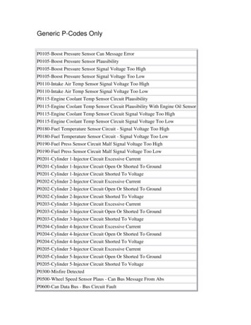
Transcription
Symmetrical Fault CurrentCalculationsECG 740
Introduction A fault in a circuit is any failure thatinterferes with the normal systemoperation. Lighting strokes cause most faults on highvoltage transmission lines producing avery high transient that greatly exceedsthe rated voltage of the line. This high voltage usually causes flashoverbetween the phases and/or the groundcreating an arc. Since the impedance of this new path isusually low, an excessive current mayflow. Faults involving ionized current paths arealso called transient faults. They usuallyclear if power is removed from the line fora short time and then restored.
Introduction If one, or two, or all three phases break orif insulators break due to fatigue orinclement weather, this fault is called apermanent fault. Approximately 75% of all faults in powersystems are transient in nature. Knowing the magnitude of the faultcurrent is important when selectingprotection equipment (type, size, etc.)
3-Phase fault current transients in synchronousgeneratorsWhen a symmetrical 3-phase faultoccurs at the terminals of asynchronous generator, the resultingcurrent flow in the phases of thegenerator appear as shown.The current can be represented as atransient DC component added on topof a symmetrical AC component.Before the fault, only AC voltages andcurrents are present, but immediatelyafter the fault, both AC and DCcurrents are present.
Fault current transients in machines When the fault occurs, the AC component of current jumps toa very large value, but the total current cannot changeinstantly since the series inductance of the machine willprevent this from happening. The transient DC component of current is just large enoughsuch that the sum of the AC and DC components just afterthe fault equals the AC current just before the fault. Since the instantaneous values of current at the moment ofthe fault are different in each phase, the magnitude of DCcomponents will be different in different phases. These DC components decay fairly quickly, but they initiallyaverage about 50 - 60% of the AC current flow the instantafter the fault occurs. The total initial current is thereforetypically 1.5 or 1.6 times the AC component alone.
Symmetrical AC component of the fault current: There are three periods of time:– Sub-transient period: first couple of cycles after the fault – ACcurrent is very large and falls rapidly;– Transient period: current falls at a slower rate;–Steady-state period: current reaches its steady value.It is possible to determine the time constants for the sub-transientand transient periods .
Fault current transients in machines The AC current flowing in the generator during the sub-transientperiod is called the sub-transient current and is denoted by I”. Thetime constant of the sub-transient current is denoted by T” and itcan be determined from the slope. This current can be as much as10 times the steady-state fault current. The AC current flowing in the generator during the transientperiod is called the transient current and is denoted by I’. Thetime constant of the transient current is denoted by T’. Thiscurrent is often as much as 5 times the steady-state fault current. After the transient period, the fault current reaches a steady-statecondition Iss. This current is obtained by dividing the inducedvoltage by the synchronous reactance:EAI ss Xs
Fault current transients in machines The rms value of the AC fault current in a synchronous generatorvaries over time asI t I " I ' e t T " I ' I ss e t T ' I ss The sub-transient and transient reactances are defined as theratio of the internal generated voltage to the sub-transient andtransient current components:EAX " I"EAX ' I'
Fault current calculationsExample 1: A 100 MVA, 13.8 kV, Y-connected, 3 phase 60 Hz synchronousgenerator is operating at the rated voltage and no load when a 3 phasefault occurs at its terminals. Its reactances per unit to the machine’s ownbase areX s 1.00 X ' 0.25 X " 0.12and the time constants areT ' 1.10 s T " 0.04 sThe initial DC component averages 50% of the initial AC component.a) What is the AC component of current in this generator the instant afterthe fault?b) What is the total current (AC DC) in the generator right after the faultoccurs?c) What will the AC component of the current be after 2 cycles? After 5 s?
Fault current calculationsThe base current of the generator can be computed asI L,baseSbase100, 000, 000 4,184 A3VL,base3 13,800The subtransient, transient, and steady-state currents are (per-unit andAmps)EA1.0I" 8.333 pu 34,900 AX " 0.12E A 1.0I' 4 pu , 700 AX ' 0.25E1.0I ss A 1 pu 4,184 AX s 1.0
Fault current calculationsa) The initial AC component of current is I” 34,900 A.b) The total current (AC and DC) at the beginning of the fault isItot 1.5I " 52,350 Ac) The AC component of current as a function of time isI t I " I ' et T" I ' I ss et T' I ss 18,200 e t0.04 12,516 eAfter 2 cycles t 1/30 s and the total AC current is 1 I 7,910 12,142 4,184 24, 236 A 30 At 5 s, the current reduces toI 5 0 133 4,184 4,317 At 1.1 4,184 A
Fault current transientsExample 2: Two generators areconnected in parallel to the lowvoltage side of a transformer.Generators G1 and G2 are eachrated at 50 MVA, 13.8 kV, with asubtransient resistance of 0.2 pu.Transformer T1 is rated at 100MVA, 13.8/115 kV with a seriesreactance of 0.08 pu andnegligible resistance.Assume that initially the voltage on the high side of the transformer is 120kV, that the transformer is unloaded, and that there are no circulatingcurrents between the generators.Calculate the subtransient fault current that will flow if a 3 phase faultoccurs at the high-voltage side of transformer.
Fault current calculationsLet choose the per-unit base values for this power system to be 100 MVAand 115 kV at the high-voltage side and 13.8 kV at the low-voltage side ofthe transformer.The subtransient reactance of the two generators to the system base isZ new Vgiven Z given Vnew 2 Snew S given Therefore:2 13,800 100, 000 X 1" X 2" 0.2 0.4 pu 13,800 50, 000 The reactance of the transformer is already given on the system base, it willnot changeX T 0.08 pu
Symmetrical fault current calculationsThe per-unit voltage on the high-voltage side of the transformer isVpu actual value 120, 000 1.044 pubase value 115, 000Thevenin equivalent circuit:Vth 1.044 puZth j0.28 puShort circuit current (pu)Isc Vth/Zth 3.73 puBase current on the high voltage side:Ibase 502 AShort circuit current (A):Isc 1,872 A
Symmetrical fault current calculations To determine the fault current in a large power system:– Create a per-phase per-unit equivalent circuit of thepower system using either sub-transient reactances(if subtransient currents are needed) or transientreactances (if transient currents are needed).– Find the Thevenin equivalent circuit looking from thefault point, then divide the Thevenin voltage by theThevenin impedance. You may use the Z-bus elements to determine thevoltages and current flows elsewhere in the system(further away from the faulted bus) Today, software tools to do the calculations for us arereadily available.
Fault current calculations using the impedancematrixBefore the fault, the voltage on bus 2 was Vf. Ifwe introduce a voltage source of value Vfbetween bus 2 and the neutral, nothing willchange in the system.Since the system operates normally before thefault, there will be no current If” through thatsource.
Fault current calculations using the impedancematrixAssume that we create a short circuit on bus 2,which forces the voltage on bus 2 to 0. This isequivalent to inserting an additional voltagesource of value -Vf in series with the existingvoltage source. The later will make the totalvoltage at bus 2 become 0.With this additional voltage source, there will bea fault current If”, which is entirely due to theinsertion of the new voltage source to thesystem. Therefore, we can use superposition toanalyze the effects of the new voltage source onthe system.The resulting current If” will be the current for theentire power system, since the other sources inthe system produced a net zero current.
Fault current calculations using the impedancematrixIf all voltage sources except –Vf” are set tozero and the impedances are converted toadmittances, the power system appears asshown.For this system, we can construct the busadmittance matrix as discussed previously:Ybusj5.00j 6.667 j16.212 j 5.0 j12.5j5.0j2.5 0j 5.0 j13.333j 5.0 j6.667j2.5j5.0 j14.167 The nodal equation describing this power system isYbus V I
Fault current calculations using the impedancematrixWith all other voltage sources set to zero, the voltage at bus 2 is –Vf, and thecurrent entering the bus 2 is –If”. Therefore, the nodal equation becomes Y11 Y 21 Y31 Y41Y12 Y13Y22 Y23Y32 Y33Y42 Y43Y14 V1 0 Y24 V f I "f Y34 V3 0 Y44 V4 0 where V1, V3, and V4 are the changes in the voltages at those busses due to thecurrent –If” injected at bus 2 by the fault.The solution is found as-1V YbusI ZbusI
Fault current calculations using the impedancematrixWhich, in the case considered, is V1 Z11 V Z f 21 V3 Z 31 V 4 Z 41Z12Z 22Z 32Z 42Z13Z 23Z 33Z 43Z14 0 Z 24 I "f Z 34 0 Z 44 0 where Zbus Ybus-1. Since only bus 2 has current injected at it, the system (12.38.1)reduces toV1 Z12 I "f V f Z 22 I "fV3 Z 32 I "fV4 Z 42 I "f
Fault current calculations using the impedancematrixTherefore, the fault current at bus 2 is just the prefault voltage Vf at bus 2 divided byZ22, the driving point impedance at bus 2.I "fVfZ 22The voltage differences at each of the nodes due to the fault current can becalculated by substitution:Z12V1 Z I VfZ 22"12 fV2 V f V fV3 Z 32 I "f Z 32VfZ 22V4 Z 42 I "f Z 42VfZ 22
Fault current calculations using the impedancematrixAssuming that the power system was running at no load conditions before the fault,it is easy to calculate the voltages at every bus during the fault. At no load, thevoltage will be the same on every bus in the power system, so the voltage on everybus in the system is Vf. The change in voltage on every bus caused by the faultcurrent –If” - so the total voltage during the fault is Z12 Z12 Z V f 1 Z 2222 V1 V f V1 V f V V V V V f 0 V 2 f 2 f ZZ V3 V f V3 V f 32 V f 1 32 f Z 22 Z 22 V4 V f V4 V f ZZ 42 V 1 42 Z 22 f Z 22 The current through a line between bus i and bus j is found byIij Yij Vi V j
Fault current calculations using the impedancematrixExample: The power system depicted earlier is working at no load when asymmetrical 3 phase fault is developed on bus 2.1. Calculate the per-unit subtransient fault current If” at bus 2.2. Calculate the per-unit voltage at every bus in the system during the subtransientperiod.3. Calculate the per-unit current I1 flowing in line 1 during the subtransient period ofthe fault.Solution:1. The per-phase per-unit equivalent circuit and the bus admittance matrix waspreviously calculated asYbusj5.00j 6.667 j16.212 j 5.0 j12.5j5.0j2.5 0j 5.0 j13.333j 5.0 j6.667j2.5j5.0 j14.167
Fault current calculations using the impedancematrixThe bus impedance matrix calculated using Matlab as the inverse of Ybus isZ bus 0 0 0 0 j 0.1515j 0.1232j 0.0934j 0.12600 0 0 0 j 0.1232j 0.2104j 0.1321j 0.14170 0 0 0 j 0.0934j 0.1321j 0.1726j 0.12820 0 0 0 j 0.1260 j 0.1417 j 0.1282 j 0.2001 For the given power system, the no-load voltage at every bus is equal to the prefault voltage at the bus that isV f 1.00 0 puThe current at the faulted bus is computed asI"f ,2 VfZ 221.00 0 4.753 90 puj 0.2104
Fault current calculations using the impedancematrixThe voltage at bus j during a symmetrical 3 phase fault at bus I can be found as Z j 0.1232 V1 1 12 V f 1 1.0 0 0.414 0 puj 0.2104 Z 22 V2 0.0 0 pu Z V3 1 32 V f 1 Z 22 Z V4 1 42 V f 1 Z 22 j 0.1321 1.0 0 0.372 0 puj 0.2104 j 0.1417 1.0 0 0.327 0 puj 0.2104 The current through the transmission line 1 is computed asI12 Y12 V1 V2 0.414 0 0.0 0 j5.0 2.07 90 puThat’s it!
voltage side of a transformer. Generators G 1 and G 2 are each rated at 50 MVA, 13.8 kV, with a subtransient resistance of 0.2 pu. Transformer T 1 is rated at 100 MVA, 13.8/115 kV with a series reactance of 0.08 pu and negligible resistance. Assume that initially the voltage on the high side of the transformer is 120