Transcription
Getting started with MIT‘sRolling Spider MATLAB Toolboxwith Parrot’s Rolling Spider Drone!An MIT take-home lab for16.30 Feedback Control SystemsProf. Sertac Karaman, Fabian RietherJanuary 28, 2016
MIT‘sRolling Spider MATLAB Toolboxwith Parrot’s Rolling Spider Drone!. let’s you design and simulate estimation and control algorithms for a drone inMATLAB/Simulink and autogenerates embedded c-code that you can use to actuallyfly the drone! After your flight, recorded data can be visualized and analyzed.
MIT‘sRolling Spider MATLAB Toolboxwith Parrot’s Rolling Spider Drone!* keep in mind that this toolbox is for educational purposes. It is therefore rather tuned to be easilyunderstood than to meet software engineering standards and amazing flight performance. The firstversion is mainly designed for experimenting with hover ngSpiderEdu for more information
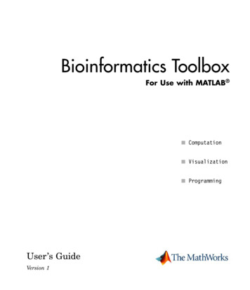
Simulate witha full Simulink modelSIMULINK model of drone’s dynamics, sensor system and compensator4
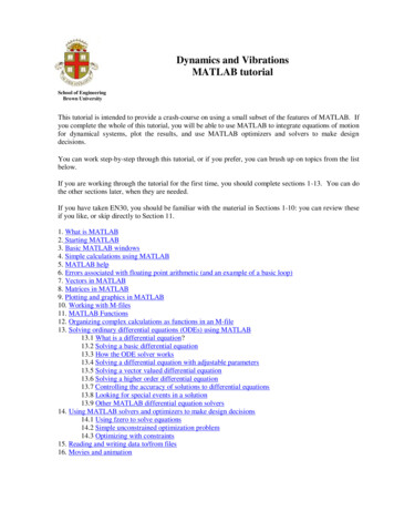
Plot datafrom simulated flightPlotting orientation, motor commands and positions from simulated flight5
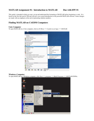
Plot datafrom real flight6
Contents Drone Hardware Toolbox––––––––„What‘s the workflow?“InstallationSimulation and control designEmbedded code generationFlyingData AnalysisDynamics AnalysisBeta-Feature: VisionResetting the drone firmware Software architecture„How did we hack it?“ Troubleshooter’s FAQ7
Drone Hardware Parrot Rolling Spider (note: not the end2015-EVO version!)1.2.3.4.5.6.7.Mass:Motors:embedded linux systemIMU:Altitude sensors:Vision:Battery:68g33g Thrust/motor6axis-accelerometer-gyroscopeSonar, Pressure sensorDownward-facing camera, 160x1207-8min flight time Bluetooth BLE adapter (if your laptop does not provide it,e.g. IOGEAR Bluetooth 4.0 USB Micro Adapter (GBU521)) Safety goggles Optional1. Additional battery and charger2. Extra set of propellers8
Toolbox„What‘s the workflow?“Estimation- &Control Design1Simulation2EmbeddedCode generation3Drone Flight via Keyboard& Data Logging4Code Compilation &Bluetooth Upload to DroneCompensator Code Integrationinto Safety, Image andCommunication CodeRedesign5Data Analysis
ToolboxA step-by-steptutorial to guide you frominstallation to simulation to flight10
ToolboxInstallation I: Equipping your ubuntu (once) (1/2) The toolbox was designed on Ubuntu 14.04. If you don’t use ubuntu natively, you can run itas a virtual machine (Windows: VMware, Mac: VMwareFusion)Your ubuntu-system should be equipped with the following programs:1.2.MATLAB 2015Lftpsudo apt-get install lftp3.Bluetooth stacksudo apt-get install bluez-compat4.expectsudo apt-get install expect5.6.MIT’s ROSMAT: Checkout Edu. Let [ROSMAT]be the path to the MIT-toolbox root folder containing the README- and LICENSE-file.Unpacked Gcc-arm-Toolchain to the file system root, so you have e.g. /opt/arm-2012.03/libexec(files can be found in [ROSMAT]/libs/gcc-arm-Toolchain)- on 64bit systems, also install the following programssudo apt-get install lib32z1 lib32ncurses5 lib32bz2-1.07.To add toolbox binaries folder to PATH:sudo gedit /.profileAppend this line, save the file, then lock out of ubuntu and back in again.export PATH firmware8.Finally, build utils programsBuildUtils.sh11
ToolboxInstallation I: Equipping your ubuntu (once) (2/2) If you are using the virtual machine provided to MIT students in 16.30 Feedback ControlSystems class, you should essentially be set. Simply activate your MATLAB and build utilsprograms (BuildUtils.sh). Have your Mathworks student account ready (check MIT’s ISTwebpage for MATLAB) and open MATLAB via the desktop icon shortcut (you might have torun it from a terminal with sudo matlab). Sidenote, here, [ROSMAT] is /RollingSpiderEdumaster/MIT MatlabToolbox.The publicly available virtual machine includes all parts that the MIT virtual machine doesapart from MATLAB. You need to expand the virtual machine’s disk space and installMATLAB.Info on MATLAB toolboxes:recommended: Communications System Toolbox, Computer Vision System Toolbox, ControlSystem Toolbox, Embedded Coder, Fixed-Point Designer, MATLAB Coder, MATLAB Compiler,MATLAB Compiler SDK, Signal Processing Toolbox, Simulink, Simulink Coder, Simulink ControlDesign, Stateflow, Symbolic Math Toolboxadditionally part of MIT’s 16.30 VirtualMachine for MIT students: Curve Fitting Toolbox, DSPSystem Toolbox, Fuzzy Logic Toolbox, Global Optimization Toolbox, Image AcquisitionToolbox, Image Processing Toolbox, Instrument Control Toolbox, MATLAB Report Generator,Model Predictive Control Toolbox, Optimization Toolbox, Robotics System Toolbox, RobustControl Toolbox, Simscape, Simulink 3D Animation, Simulink Design Optimization, SimulinkDesign Verifier, Simulink Report Generator, Simulink Verification and Validation, System12Identification Toolbox, Vision HDL Toolbox, Wavelet Toolbox
ToolboxInstallation II: Flashing the drone (once) (1/3)The consumer drone has to be flashed with a custom firmware once.1.Connect drone via USB (if using a virtual machine, make sure to connect to ubuntu)2.Open fvt6.txt on drone USB, note down name and MAC address.(If no fvt6.txt can be found, skip step 3 for now and run sudo hcitool scan after step 9. Your drone should be listed, read theMAC address from there. Then do step 3 and continue with step 10 afterwards.)3.Save MAC address to DroneMACaddress.txt by entering, in a terminalDroneSetMACaddress.sh [MACADDRESS]4.Upload main firmware to drone by runningEDUfirmwareUploadSYS.sh(Info: This script copies rollingspider.edu.plf to root folder of drone USB device)5.6.7.8.Disconnect drone by ejecting USB device and removing USB cableCharge batteryInsert batteryWait until LEDs stopped blinking (firmware is now updated)(Note: If LEDs never blinked, redo step 1 & 3-8.)9.Plug in bluetooth adapter (if necessary) continue on next slide!13
ToolboxInstallation II: Flashing the drone (once) (2/3)10. Connect drone to computer by runningDroneConnect.sh11. Upload firmware files by runningEDUfirmwareUploadFILES.sh(Info: uploads files in [ROSMAT]/libs/EDUfirmwareFILES to drone via ftp and IP 192.168.1.1)12. Reboot droneDroneReboot.sh continue on next slide!14
ToolboxInstallation II: Flashing the drone (once) (3/3)13. Connect drone againDroneConnect.sh14. Initialize drone firmwareEDUfirmwareInitialize.sh(Info: This script moves firmware files to right locations and grants permissions rights:mv /data/edu/dragon-prog /usr/bin/chmod x /usr/bin/dragon-progmv /data/edu/SpiderFlight.sh /bin/chmod x /bin/SpiderFlight.sh)15. Initialize droneDroneInitialize.sh(Info: This script write the computer’s IP address to the drone’s parameter file)16. Done with flashing. Nice!15
Toolbox(Dis-)Connecting to the drone (after restarts, .) If you want to disconnect, run in a terminalDroneDisconnect.sh To connect run in a terminalDroneConnect.sh16
ToolboxWorkflow I: Simulation and Control Design1.Open MATLAB and navigate to the [ROSMAT]/trunk/matlab/ folder–––2.3.4.Simulation/ contains the Simulink files to design and simulate the drone with its estimators and controllers.libs/ contains parts of Peter Corke’s Robotics Toolbox to simulate the dynamics of a drone, updated to(somewhat) match Parrot’s Rolling SpiderExperimentAnalyzer/ contains various files to analyze sensor and dynamics data recorded while flying, orprocessing times from threads running on the drone.Run startup.m, then open sim quadrotor.slxDesign your controllers.As a first approach, copy-paste a preset controller: Open controllers/controller PID/controller PID.slx,copy the ControllerPID block and insert it at the correct place in sim quadrotor.slx.For further design, Simulink can be used (mostly) freely, but keep in mind that c-code for a drone withlow processing-power will be generated. (See section “Troubleshooter’s FAQ” for more hints).Do not change the input/output-ports of the Drone Compensator to avoid manual changes in theresulting c-code.Open SCOPES to have variables plotted, press to simulateOr: After simulating, go to MATLAB, type FlightAnalyzer17
ToolboxWorkflow II: Embedded code generation (1/2)1. Rightclick on the Drones Compensator block, select „Build This Subsystem“.In the pop-up dialogue box, click Build.18
ToolboxWorkflow II: Embedded code generation (2/2)2.Upload your controller(If disconnected from drone: DroneConnect.sh first)DroneUploadEmbeddedCode.sh(Info: this script packs the autogenerated code with the drone’s c-code framework using the binary PackEmbeddedCode, builds thecode with make in [ROSMAT]/trunk/embcode/build-arm and uploads new shared library [ROSMAT]/DroneExchange/librsedu.so todrone using ftp to 192.168.1.1) Expert level - With altered Simulink input/output-ports:Do the steps from step 2 manually. After running PackEmbeddedCode in its folder,replace code paragraph “Input/Outputport Declarations IO(x)” of SIMULINK compensator block in rsedu control.c with input/output-portdeclarations found in ert main.c. Note: You also have to update function calls forinitializing, stepping and packing the model in rsedu control.c; found inrsedu control.c with comments “IO(2)” and “IO(3)”)19
ToolboxWorkflow III: Flying (1) – Flight PhasesThe drone’s flight is split into 3 phases1.Sensor calibrationDrone sits on the floor for 2 seconds to calibrate its sensors.2.Take-offTake-off for 1 second with given power and attitude control only3.Actual flight20
ToolboxWorkflow III: Flying (2) – Safety Procedures Make yourself aware of issues described on du/issues and read the Troubleshooter’s FAQ section inthis document (p. 33) Don’t charge batteries unattended Ensure people, animal, property, etc. safetyStick to Parrot’s safety guidelines (see print-out)Wear safety glasses all the time Always fly with wheels installedOnly fly indoors, open area 10’x10’ over non-glossy floor Always test a new program with DroneTest.sh first, instead of DroneRun.shStick to software safety procedures (p.22) Be smart!21
ToolboxWorkflow III: Flying (3) – Software Safety If the drone’s main script does not crash itself, it shuts down the motors incase of a crash or a loss of optical flowA single flight is aborted automatically after 20 seconds (see sectionTroubleshooter’s FAQ)For all other cases (and they will happen!)Always have a separate terminal open, enter telnet 192.168.1.1 (you shouldalready be connected to the drone), now you are logged directly onto thedrone.Typekillall –s SIGKILL dragon-prog; gpio 39 –d ho 1;test-SIP6 pwm –S;and be ready to execute this line when the drones goes crazy!22
ToolboxWorkflow III: Flying (4) – SettingsIf you want to enable/disable software features With the drone connected, log onto drone in a new terminal telnet 192.168.1.1, thenvi /data/edu/params/paramsEDU.dat Enable features with replacing ‘0’ by ‘1’FEAT TIME:records timestamps for entering and leaving the functions rsedu control,rsedu of (optical flow) and rsedu vis (visual position reconstruction)FEAT OF ACTIVE:optical flow is used to stabilize positionFEAT POSVIS RUN:camera looks for landmark setup and reconstructs position if alllandmarks found; visually reconstructed position is recordedFEAT POSVIS USE:use visually reconstructed position to enhance kalman positionestimateFEAT NOLOOK:compute color conversion, landmark matching etc. online instead of using aprecomputed lookup-table (don’t use this, too slow)FEAT IMSAVE:1: saves images (camera runs at 60Hz, images being recorded/saved at 10Hz)2: images are being streamed to ubuntu machine (see rsedu vis.c foradditional instructions)FEAT NOSAFETY:1: drone is not automatically shut down when take off-surface is not level, z-axis –acceleration is positive or x-y-accelerations exceed 6m/s² (dangerous setting!)POWERGAINcannot be changed manually23
ToolboxWorkflow III: Flying (5)1.Start KeyboardPilot, i.e. the server providing the reference values, withDroneKeyboardPilot.sh2.3.In another terminal- DroneTest.sh for a test run with 10% Power- DroneRun.sh for a full runGo back to the KeyboardPilot’s terminal , hit keyboard buttons(do not keep pressing them!)Abort flightReset pitch/roll reference 𝟎. 𝟐𝒎 altitude 𝟎. 𝟎𝟓 roll 𝟎. 𝟎𝟓 pitch 𝟎. 𝟔𝒎 altitude 𝟎. 𝟐 yaw24
ToolboxWorkflow IV: Data Analysis – FlightAnalyzer1. Download RSdata.mat from drone via ftp to[ROSMAT]/DroneExchange/ by runningDroneDownloadFlightData.sh(Alternatively (faster), connect drone via usb and runDroneDownloadFlightDataUSB.sh2. In MATLAB, load RSdata.mat (double-click)3. Run MATLAB-script FlightAnalyzer25
ToolboxWorkflow IV: Data Analysis – Software in the LoopInstead of a full-stack simulation, feed recorded sensor datathrough the Simulink Drones Compensator block to see whathappened under the hood of estimators and controllers duringthe recorded flight.1. Make sure to have loaded some flight data RSdata.mat andhave run the FlightAnalyzer with recorded data once2. In MATLAB, navigate to [ROSMAT]/trunk/matlab/Simulation3. Use Simulink model sim SoftwareIntheLoop Compensator.slx26
ToolboxWorkflow IV: Data Analysis – Processing Times1. Download folder ptimes/ from drone withDroneDownloadPTimes.sh2. Run matlab script PTimesAnalyzer27
ToolboxWorkflow V: Dynamics Analysis Check the pole placement fullstate controllers in[ROSMAT]/trunk/matlab/Simulation/controllers/ to seeexamples how to utilize MATLAB and Simulink to linearizedynamics to design fullstate controllers28
ToolboxWorkflow VI: Betafeature-Vision Recording and postprocessing images:Enable the image-save feature to record images (p. 24), fly.Then, process recorded images: Download recorded, binary images, convert toppm and save vision-inferred poses into pose.txt1.Download binary images from drone2.Run3.Follow instructionsSee [ROSMAT]/DataExchange/imgs/processed for ppm, poses, and shVisionPrePostProcessor.shUpdating landmark setup:When using a different landmark setup, econstructionParameters.m to computenewvision matrices, then update them in [ROSMAT]/trunk/embcode/rsedu vis helpers.c The landmark’s descriptors (HSV-values) might need to be updated(VisionPrePostProcessor/main offboard image.c)29
ToolboxWorkflow VI: Betafeature-Vision Landmarks are colored markers on the floor Standard setup:(14, 13)(13, -22)xy(-24, -23)(-24, 14)[cm]30
ToolboxResetting the drone To fully reset the drone to its original state,– Do a software update via ider/: Click on "Software Update“ and then "Download“,follow the instructions on the webpage.31
Software Interface„How did we hack it?“ Drone calls our control code @200Hz,input: sensor dataoutput: motor commandsvoid RSEDU control(HAL acquisition t* hal sensors data,HAL command t* hal sensors cmd) Drone calls our image processing code @60Hzinput: image buffervoid RSEDU image processing(void * imagebuffer)FIFO-pipes Drone calls our optical flow code @60Hzinput: computed optical flowvoid RSEDU optical flow(float vx, float vy, float vz,intdefined,float qualityIndicator)32
ToolboxTroubleshooter’s FAQ33
ToolboxTroubleshooter’s FAQ: Work flowAfter pulling a new version from the official github, make sure to run BuildUtils.sh34
ToolboxTroubleshooter’s FAQ: A low battery level can cause multiple problems.––––– Motors, Crashes. the takeoff is slower - unfortunately, sonar and vision measurements work best above 0.5m. Witha slower takeoff, the drone cannot reliably use those measurements for a longer time!. the motors are "weaker", the control impact therefore too. the CPU behavior can become unpredictable.Just having the drone up and running (without flying) drains the battery - it is an embeddedcomputer after all.Bottom line: Always charge your second battery while working with the first one.Flight time is currently limited by software to 20 seconds for a single flight. This can beextended (rsedu control.c , variable onCycles). However, note that recoding data takes space(especially when images are recorded). There is only a single-digit mb space available on thedrone. Also note that you might have to increase the data buffer size for loggingFlightAnalyzer-ready data (see make-file in embcode/build arm)If drone says "RSEDU IP not found", reupload your code (the underlying problem is that theuploaded shared library is not fully recognized (usually linker issues))Motors may not start because of default override from manufacturer firmware. This canoccur with the drone having been upside down, too high currents while crashing or a lowbattery. Try starting the drone again, or reboot it with new battery.After a crash, check the plots of all sensor for irregularities.35
ToolboxTroubleshooter’s FAQ: Simulation, State EstimationThe underlying dynamics are modeled using Euler angles. Due to singularities flownmaneuvers have to be limited to 90 for pitch and roll.Note that the position estimate is reset to zero when switching back to position control fromattitude control.Note that the bias of the IMU is not iteratively estimated but considered to be constantduring a flight. It is inferred from data gathered right before takeoff – make sure to start onlevel ground.The kalman filters have outlier handling procedures based on the deviation of the currentstate estimates to recent measurements. This kind of outlier handling is overly simple. Also, itcan make the estimators useless for aggressive maneuvers.Ideas for your simple tweaks: If Kalman-estimates and measurement updates differ largelyover a significant period of time, consider resetting kalman-estimates.Ideas for your simple tweaks : Make use of the pressure sensor to detect outliers of the sonarmeasurement (e.g. caused by obstacles). Be careful with how to deal with calibratingpressure offset and drift. E.g., Check if jumps of the current sonar-based altitude estimate arerealistic/valid. If not, switch to pressure-based estimate and possibly back to the sonar-basedone once that is close to the pressure-based one again.36
ToolboxTroubleshooter’s FAQ: Model AccuracyThe optical flow module is modeled (in SIMULINK) very far from the real implementation.Still, the optical flow is the main input to estimate the drone's velocity. Now, if we tunecontrollers in simulation such that they respond to velocity in a very sensitive way, we willlikely run into problems running that controller on the real drone (because we tuned thecontroller to a state (velocity) that is badly estimated (on the real drone) and has low modelaccuracy!).If the plant model was known with perfect accuracy, we could design a controller that maxesout the performance. However, with a real-world system that is modeled with inaccuracies,there is a need for robustness, achievable with trading of controller performance. You willnotice this when tuning the drone’s controller gains in the simulation. If you max out gains insimulation, the real drone will be unstable!In a simulation without drag, the sensed acceleration by the accelerometer will always pointin the direction of the z-axis. Therefore, correcting the drift of the integration of angular ratesfrom the gyro (to estimate the attitude) would only be possible in perfect hover, or withmaking use of the current attitude estimate. In real life, drag brings the drone into a steadystate with zero acceleration so we can infer the attitude from the direction of thegravitational vector.The drone does have a motor lag, i.e. the propeller rate does not change instantly. This effectis not modeled in the simulation and not addressed by the controllers. A lead compensatorcould help compensating for this lag.37
ToolboxTroubleshooter’s FAQ: From Simulation to C-Code Set simulation time to inf (otherwise the onboard controller on the drone will be limited tothe simulation time you set in the Simulink simulation)Avoid SIMULINK blocks that require zero-crossing detection.Avoid huge matrix multiplications.Avoid logging a lot of signals.Be smart, your SIMULINK model has to run on-board with limited computing power! Do not move files with MATLAB’s file explorer, it might mess with file permissions38
ToolboxTroubleshooter’s FAQ: Beta-feature VisionThe camera pose reconstruction algorithm assumes zero pitch and roll angle when seeing thelandmarks.39
tutorial to guide you from installation to simulation to flight 10 . Toolbox The toolbox was designed on Ubuntu 14.04. If you dont use ubuntu natively, you can run it . MATLAB Coder, MATLAB Compiler, MATLAB Compiler SDK, Signal Processing Toolbox, Simulink, Simulink Coder,