Transcription
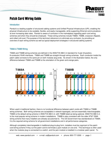
Online Wiring Informa onStart by selec ng the model year of your coach from thele frame. Note that only 1990 model year and newer areavailable online.The Electrical PartsIden fica on Listprovides terminals,connectors, conductors,receptacles, lamps,legends and otherreference items neededto read our wiringinstalla on drawings.The list of available models is divided up byfamilies. Select your model.The wiring informa on is broken down by 110 volt, 12 volt,and func on. We have both diagrams that show the logicand installa on drawings that illustrate rou ng of wires andthe loca on of electrical components.The WiringIden fica on Guideprovides the codesprinted on each wire.Using this code, you candetermine purpose andto – from loca on of thewire.Acrobat Reader is used to display the Wiring Informa on. Helpful func ons are noted below. For addi onal informa on, see the Acrobat Reader on‐line Help.FIND—use CTRL‐F or the find tool toquickly locate text.ZOOM—use the zoom toolfor be er clarity.to magnify an areaFIT IN WINDOW—use the fit in window tool toredisplay the en re page.
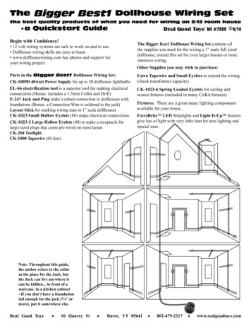
Title BlockLower right corner of the drawing will contain a tle block. Depending on what sheet and/or frame of the drawing you are viewing, the tle block will be in a different format. The important elements of the tle block are noted below.FIRST USED—Unit the drawing wasfirst used onTITLE—DescripƟon of the drawingPART NO/DWG NO—Winnebago Industriespart numberSHEET/FRAME—Sheet number of the drawing (1 of 8 or S1)Frame number of the drawing (F1)
Drawing BorderTo navigate a drawing, it is broken down into zones or areas. The drawing border contains the zone loca ons—alpha loca ons on the side borders and numeric loca onson the top & bo om borders. You locate an object in a drawing similarly to loca ng a city on a road map. By using the zone locaters in the drawing border, you canlocate objects on a drawing.For example:To locate the housing at zone D‐3, first locate zone D in the right or le side drawing border, then locate zone 3 in the top or bo om drawing border. The area on thedrawing where those two meet is referenced as zone D‐3.In this example, the housing at zone D‐3specifies that it connects to a housing onsheet 8 zone C‐8.CONNECTS TOWIRE ASM‐TVCABT, SIDE(SHT 8, C‐8)(LOCATED IN BASEOF FRT RH TV CABT)The housing at zone C‐8 on sheet 8 specifiesthat is connects to a housing on sheet 8zone D‐3.CONNECT TOWIRE ASM‐JUMPER, SPEAKER(SHT 8, D‐3)(LOCATED IN BASE
Mul ‐Frame DrawingsA mul ‐frame drawing is a long drawing that is split into sec ons or frames. Frame coun ng begins on the right and goes le .A drawing that does not contain frames is surrounded on all four sides by a border. A mul ‐frame drawing will not have a border on the right and/or le sides.The following example shows sheet 1 of part number 158392 that is split into 3 frames. Frame 1 has a drawing border only on the right edge but not the le edge;Frame 2 does not have a border on either the le or right edge; and Frame 3 has a border only on the le edge.Sheet 1 Frame 3S1 F3Sheet 1 Frame 2S1 F2Sheet 1 Frame 1S1 F1
Delta Notes and OpƟon CodesDelta notes specify important informa on and are located in the lower lecorner of the drawing. (Note on a mul ‐frame drawing, the delta notes arelocated on the last frame.) The delta note is referenced in the drawing by thedelta symboland the note number.Op on codes are located at zone A‐1 and list the op onal feature code and adescrip on of the op onal feature. Op on codes are noted in the drawingwith an oval.Op on codeslocated on thedrawing signifythat that noteor view pertainto the op on.Op on codes locateddirectly above thetle block signify thatthe en re drawingpertains to thatop on.
Detail ViewsA detail view is an enlarged area of part of the drawing. Detail views are defined one of two ways. First by dashed lines and arrows around the area to be enlarged.A detail iden fier is noted between the arrows. Secondly, just a callout specifying the detail. Locate the detail view on the drawing. Note that the detail view may belocated on another sheet of the drawing.158386 Sheet 3158386 Sheet 5Detail EK—Note that this detail isnot on the same sheet as thecallout.158385 Sheet 1Detail AA—Note that the detail view is on the same page as the callout.
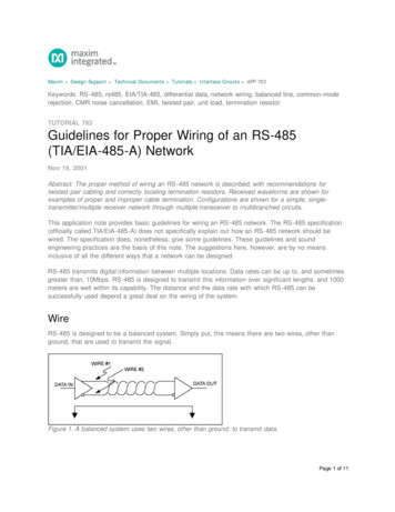
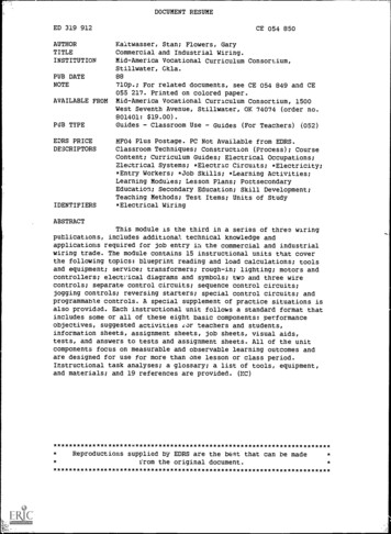
Wiring IdenƟficaƟon—12 voltWinnebago Industries built motorhomes have been using “two‐color” wiring on 12‐volt wiring since the early 1990s. The wiring is iden fied first by color, and then with acombina on of numeric and alpha characters stamped or printed directly on the wire. Beginning in 1999, the revision level of the assembly is also stamped on the wire.This wiring iden fica on is printed on each wire every inch making it convenient to find in close quarters.This photo shows a yellow and a white wire. Note the eight‐digit part number (146740‐01) therevision level (A) and the three‐character alpha designa on (JJT) on the yellow wire.The eight‐digit part number and the revision level specify the wiring assembly to which the JJT wirebelongs and the alpha characters are used to iden fy the purpose or func on of the wire.The Winnebago Wiring IdenƟficaƟon Guide must be referenced to determine the purpose or func on of the JJT wire. Locate the JJT code in the Wiring Iden fica on Guide(use the Find func on of Acrobat Reader to easily locate JJT).This describes a 14 gauge yellow wire that connects to a 15 amp power source from the coach ba ery (versus the chassis ba ery).
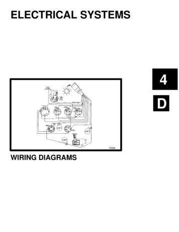
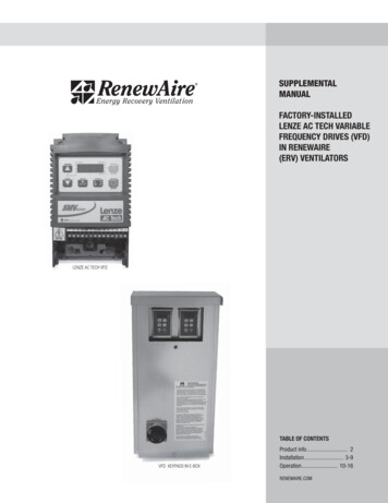
Wiring Iden fica on—120 voltBeginning with the 2007 models, 120‐volt romex in the motor home is now iden fiable with a combina on of color and text. Each wire gauge is iden fiable by the color ofthe PVC insula on jacket and, similar to the 12‐volt wiring, the text printed on the wire insula on jacket iden fies the intended purpose or specific func on of the wire. ThePVC jacket on the romex is stamped with informa on including the gauge of wire, the voltage limita ons, and "iden fiers" that dictate the usage or limita ons for the romex(i.e., interior applica ons versus an in‐conduit, temperature restric ons / ra ngs on the wire insula on, etc.).Orange PVC JacketAWG 10 Wire—30 Amp.—Typically a Power SupplyYellow PVC JacketAWG 12 Wire—20 Amp.—Air Condi oning Circuits, Energy Management System, Washer / Dryer, Water HeaterWhite PVC JacketAWG 14 Wire—15 Amp.—Receptacles, Refrigerator, Microwave OvenThe photo shows several examples of romex with different informa on printed on each. This informa on is printed every 3 inches for easy iden fica on and tracing. Whatdoes this informa on tell us?1. Note the text on the upper white AWG 14 wire. It calls out “Blue recps. 1” and “17000 mm”. Addi onally, there are arrows ( ) and “current flow” comments. Thisinforma on is indica ng the following: The “Blue” labeled 15‐amp. circuit breaker in the 120‐volt load center is providing power to this romex. The romex is 17,000 mm long (divide 17,000 by 25.4 669.29 inches). Arrows indicate the power flow away from the load center (beneficial for proper wiring of GFCI outlets).2. Note the text on the lower white AWG 14 wire. It calls out “Black microwave” and “4800 mm”. It con nues on with the number “155854” and “rev. c”. This informa on isindica ng the following: The “Black” labeled 15‐amp. circuit breaker in the 120‐volt load center is providing power to this romex. The romex is 4,800 mm in length (188.97 inches long). The “155854” is a reference to a wire assembly drawing part number and the “rev. c” is a revision code. The code informa on iden fies a wiring change(s) with thewire assembly and is intended for factory use.
Wiring Iden fica on—120 volt, con nuedInstalla on DrawingsThe Winnebago Industries wiring installa on drawings illustrate wiring placement through‐out the motor home. There is even more detail available now.1. Refer to the area highlighted in pink. Note the “color callouts” on the various circuitbreakers. This color I.D. correlates directly with the "color callout text" on the 120‐voltromex.2. Refer to the area highlighted in blue. Note the metal “knockout” holes in the upper rightcorner of the load center and iden fy the romex “exit points” from the breaker panel.Wiring DiagramsThe Winnebago Industries wiring diagrams provide us with the interconnec on of thevarious appliances and receptacles to the 120‐volt load center and EMS or EnergyManagement Systems “shedder boards”, etc.1. Refer to the area highlighted in yellow. Note the color callouts on the variouscircuit breakers. This color I.D. correlates directly with the “color callout text” onthe 120‐volt romex.2. Refer to the areas highlighted in green. Star ng at the circuit breakers, followseveral of the romex and note the wiring AWG callouts (14‐2 and 12‐2) and theloads supported by the respec ve romex.
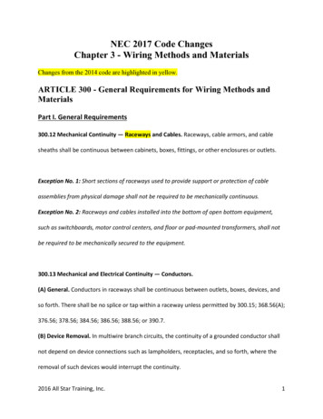
Wire Tracing on Diagram DrawingsWire tracing is required when an electrical component is inopera ve. We have chosen a familiar item, the Kwikee electric step, for our example and will describe step‐by‐stephow to iden fy and trace one electrical circuit.1. Since the diagram does not contain a table of contents, it is necessary to scan the drawing to iden fy a por on of the affected circuit. The 4‐pin connector that mates to theelectric step plug is located at A‐3 (Sheet 1).2. Note the informa on available next to the connector. Each pin in the connector is iden fied by it’s loca on and by the wire a ached. There are occasions where it will benecessary to iden fy the func on of each wire to properly diagnose a problem. This will require use of the Wiring Iden fica on Guide. Delta note 4 makes reference to themanufacturer’s diagram for addi onal informa on.3. For this example, we have iden fied wire “KA” that should have power but does not. Star ng at the connector at A‐3, follow the yellow 12‐gauge “KA” wire up and to theright side of the sheet.4, The KA wire turns up to a 15‐pin mate‐lock connector. Note the wiring iden fica on informa on to the right of the connector and you will see the “KA” wire is in pin posi onnumber 15.5. The text above this connector iden fies the loca on for the other half of the mate‐lock connector on the drawing in addi on to the connector’s physical loca on in themotorhome. The (SHT 6, C‐4) informa on tells you to go to sheet 6, zone C‐4.6. From the 15‐pin connector at C‐4, find the “KA” wire and follow it to the 25 amp breaker in the breaker buss. Note the loca on informa on to the right of the buss.7. Follow the wire path from the 25 amp breaker to the 8 gauge black wire that eventually connects to the isolated stud located in the ba ery compartment.Sheet 1Sheet 6
Wire Tracing on InstallaƟon DrawingsInstalla on drawings offer addi onal informa on that can expedite a repair effort. As noted in the wiring diagram tracing sec on, a wiring diagram verbally describes aconnector’s loca on in the motorhome. Installa on drawings not only illustrate the connectors loca on, they depict the wiring path ge ng from point A to point B. Ourmotorhomes range from 20 to 40 feet in length and having knowledge of a wire harness’s rou ng throughout the vehicle can narrow the search.1. Since there are a variety of installa on drawings to choose from, it is important to es mate where we would most likely find a specific wire harness and then start the ini alsearch in that drawing. For example, there is an installa on drawing for all of the dash related components – see the Front End Wiring Installa on drawing; there areinstalla on drawings for harnesses found below the coach floor – see the Chassis Wiring Installa on drawing; as well as installa on drawings for inside the coach.2. Since there is not a table of contents, it is necessary to scan the drawings for any details that would help iden fy the component, wiring connector, or the wire harnessyou’re looking for. This would include illustra ons of items like a power converter or text calling out a harness loca on inside the motorhome.An example of a harness rou ng is illustrated here. Thehighligh ng illustrates the wire harness loca on in theright rear room extension.In this example, the harness includes the lights andspeakers in the overhead cabinets above the bed, thedecorator wall lamps, the bedroom stereo, the slide outlatch, the wall switches, and the connec ons to the frontTV and video switch box.The wire harness passes from the overhead to the floorinside the storage cabinet and nightstand, then runsforward to the TV cabinet and up to the wall switchesand video switch box. The harness connects to the maincoach loom under the bed with a 4, 12, and 15 pinconnector along with red, orange, blue, and yellow coaxcables.
Electrical Parts Iden fica on ListThe installa on drawings contain balloon callouts iden fying electrical components. You must refer to the Electrical Parts Iden fica on List to cross‐reference this calloutiden fica on with the Winnebago Industries part numbers.In this example: the balloon callout LMU3‐2 cross‐references to: LAMP 138116‐01‐CHTSCREW (SUPPLIED)BULB 123918‐01‐000 (quan ty 3)CONNECTOR 058028‐01‐000 (quan ty 2)Installa on Drawing 158676Electrical Parts Iden fica on List
The wiring informa on is broken down by 110 volt, 12 volt, and func on. We have both diagrams that show the logic and installa on drawings that illustrate rou ng of wires and the loca on of electrical components. Acrobat Reader is used to display the Wiri