Transcription
ELECTRICAL SYSTEMS4D72938WIRING DIAGRAMSINDEX
Table of ContentsPageWiring Colors for MerCruiser . . . . . . . . . . . . . . . 4D-1Wire Color Abbreviations . . . . . . . . . . . . . . . 4D-1Wiring Diagrams . . . . . . . . . . . . . . . . . . . . . . . . . 4D-2MCM 3.0L/3.0LX . . . . . . . . . . . . . . . . . . . . . . 4D-2MCM V-6 Alpha Drive Engines . . . . . . . . . . 4D-3MCM V-8 Alpha Drive Engines . . . . . . . . . . 4D-4MCM V-8 Bravo Drive Engines . . . . . . . . . . 4D-5MIE V-8 All Inboard and Ski Engines . . . . . 4D-6MCM Quicksilver Instrumentation . . . . . . . . 4D-7MIE Quicksilver Instrumentation . . . . . . . . . 4D-8Dual Station Wiring (Using a Neutral SafetySwitch in Only one Remote Control) . . . . . . 4D-9Dual Station Wiring (Using A Neutral SafetySwitch In both Remote Controls) . . . . . . . . 4D-10Dual Station Wiring (Using a Neutral SafetySwitch in Engine Wiring Harness) . . . . . . . 4D-11Gauges . . . . . . . . . . . . . . . . . . . . . . . . . . . . . . . . 4D-12Battery Meter Gauge . . . . . . . . . . . . . . . . . . 4D-12Cruiselog . . . . . . . . . . . . . . . . . . . . . . . . . . . . 4D-12Fuel Gauge and Sender . . . . . . . . . . . . . . . 4D-12Audio Warning System . . . . . . . . . . . . . . . . 4D-13Water Temperature Gauge . . . . . . . . . . . . . 4D-13Oil Pressure Gauge . . . . . . . . . . . . . . . . . . . 4D-13Clock . . . . . . . . . . . . . . . . . . . . . . . . . . . . . . . 4D-13Wiring Diagrams for 502 EFI . . . . . . . . . . . 4D-15EFI Wiring Diagram . . . . . . . . . . . . . . . . . . . 4D-17ECM Component Connector Charts . . . . . . . 4D-21INDEX4D - WIRINGDIAGRAMS4D-0- WIRINGDIAGRAMS90-806535 893
Wiring Colors for MerCruiserBIA Color CodeWhere UsedBlackAll GroundsBrownReference Electrode-MerCathodeOrangeAnode Electrode-MerCathodeLt. Blue/WhiteTrim- ”Up” SwitchGrayTachometer SignalGreen/WhiteTrim -”Down” SwitchTanWater Temperature Sender to GaugeLt. BlueOil Pressure Sender to GaugePinkFuel Gauge Sender to GaugeBrown/WhiteTrim Sender to Trim GaugePurple/WhiteTrim-”Trailer” SwitchRedUnprotected Wires from BatteryRed/PurpleProtected (Fused) Wires from BatteryRed/PurpleProtected ( 12V) to Trim PanelOrangeAlternator OutputPurple/YellowBallast BypassPurpleIgnition Switch ( 12 V)Yellow/RedStarter Switch to Starter Solenoid to Neutral StartSwitchWire Color ellowLITLightDRKDarkINDEX90-806535940 893WIRING DIAGRAMS - 4D-1
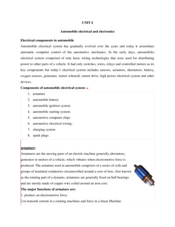
Wiring DiagramsMCM 3.0L/3.0LX2112334311262453NOTE : Gray lead for use with service tachometer.A -Ignition System1 -Distributor2 -Shift Cutout Switch3 -Filter4 -Ignition CoilB -Starting System1 -Alternator2 -Electric Choke (2 BBL Only)3 -Ground Bolt4 -Starter5 -Circuit Breaker6 -Starter Slave SolenoidC-Audio Warning System1 -Water Temperature2 -Drive Unit Oil Level (If Equipped)3 -Oil Pressure SwitchD -Instrumentation System1 -Oil Pressure Sender2 -Water Temperature Sender3 -Trim SenderINDEX4D-2 - WIRING DIAGRAMS90-806535 893
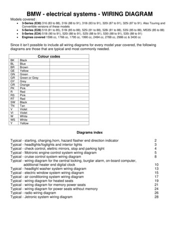
MCM V-6 Alpha Drive Engines31122WHT/REDWHT/GRN3GRY1PUR34264512371877A -Ignition System1 -Distributor2 -Shift Cutout Switch3 -Terminal Block4 -Ignition CoilB -Starting System1 -Alternator2 -Electric Choke (2 BBL Only)3 -Ground Bolt4 -Starter5 -Circuit Breaker6 -Starter Slave Solenoid7 -Fuel PumpC-Audio Warning System1 -Water Temperature2 -Drive Unit Oil Level (If Equipped)3 -Oil Pressure SwitchD -Instrumentation System1 -Oil Pressure Sender2 -Water Temperature Sender3 -Trim SenderINDEX90-806535940 893WIRING DIAGRAMS - 4D-3
MCM V-8 Alpha Drive Engines21123WHT/REDWHT/GRNGRY31PUR34264153272935A -Ignition System1 -Distributor2 -Shift Cutout Switch3 -Terminal Block4 -Ignition CoilB -Starting System1 -Alternator2 -Electric Choke (2 BBL Only)3 -Ground Bolt4 -Starter5 -Circuit Breaker6 -Starter Slave SolenoidC-Audio Warning System1 -Water Temperature2 -Drive Unit Oil Level (If Equipped)3 -Oil Pressure SwitchD -Instrumentation System1 -Oil Pressure Sender2 -Water Temperature Sender3 -Trim SenderINDEX4D-4 - WIRING DIAGRAMS90-806535 893
MCM V-8 Bravo Drive Engines2311WHT/REDWHT/GRNGRY21PUR235341272936A -Ignition System1 -Distributor2 -Ignition CoilB-Starting and Charging Systems1 -Alternator2 -Ground Stud3 -Starter Motor4 -Circuit Breaker5 -Starter Slave SolenoidC -Audio Warning System1 -Water Temperature2 -Drive Unit Oil Level (If Equipped)3 -Oil Pressure SwitchD -Instrumentation System1 -Oil Pressure Sender2 -Trim Sender3 -Water Temperature SenderINDEX90-806535940 893WIRING DIAGRAMS - 4D-5
MIE V-8 All Inboard and Ski Engines1132WHT/REDWHT/GRNGRY1PUR2263415729372NOTE : Taped back brown and black wire may be used for an accessory. LOAD MUST NOT EXCEED 5 AMPSA-Ignition System6 -StarterSlave Solenoid1 -DistributorC -Audio Warning System2 -Ignition Coil1 -Water Temperature2 -Transmission Fluid TempertureB -Starting and Charging System3 -Oil Pressure1 -Alternator2 -Ground StudD -Instrumention System3 -Starer Motor1 -Oil Pressure Sender4 -Circuit Breaker2 -Water Temperature Sender5 -Neutral Safety SwitchINDEX4D-6 - WIRING DIAGRAMS90-806535 893
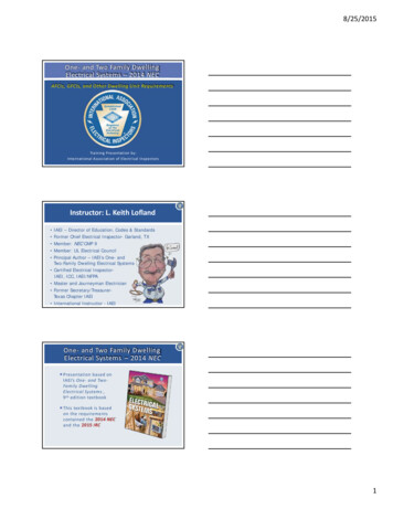
MCM Quicksilver Instrumentation82143596BSI772938NOTE 1: Connect wires together with screw and hex nut. Apply Quicksilver Liquid Neoprene to connection andslide rubber sleeve over connection.NOTE 2: Power for a second fused accessory panel may be tasken from this connection. Load MUST NOT exceed35-40 amps. Panel ground wire MUST BE connected to instrument terminal that has an 8 gauge black (ground)harness wire connected to it.123456789-TachomterAudio Warning Buzzer (if Equipped)Oil PressureWater TemperatureBattery MeterIgnition SwitchTrim IndicatorTo 12 Volt Source (purple wire connection)20 Ampere FuseINDEX90-806535940 893WIRING DIAGRAMS - 4D-7
MIE Quicksilver Instrumentation7214365BSI872939NOTE 1: Connect wires together with screw and hex nut. Apply Quicksilver Liquid Neoprene to connection andslide rubber sleeve over connection.NOTE 2: Power for a second fused accessory panel may be tasken from this connection. Load MUST NOT exceed35-40 amps. Panel ground wire MUST BE connected to instrument terminal that has an 8 gauge black (ground)harness wire connected to it.12345678-TachomterAudio Warning Buzzer (if Equipped)Oil PressureWater TemperatureBattery MeterIgnition SwitchTo 12 Volt Source (purple wire connection)20 Ampere FuseINDEX4D-8 - WIRING DIAGRAMS90-806535 893
Dual Station Wiring (Using a Neutral Safety Switch in Only one Remote KBLKBLKGRYLT. BLUPURNOTE 3YEL/RED21RED/PUR54BRN/WHTGNDLTBSI3NOTE 1SW PURRED/PURORNTANPURBLKPURLT. BLUBLKBLKPURPURGRYYEL/REDORNNOTE 2YEL/REDNOTE 3NOTE 3NOTE 3BNOTE 1YEL/REDBRN/WHTYEL/RED672940NOTE 1: Brown/white wire is taped back at instrument end. If installing on boat that is equipped with MerCruiser Stern Drive, brown/whitewire is connected to trim sender terminal block. If installing on MerCruiser Inboard, brown/white wire is taped back at engine end, or it maybe used for an accessory (limit 5 amperes)NOTE 2 : An accessory fuse panel may be connected at this location. The combined current draw of the primary station and secondarystation MUST NOT exceed 35 amperes.NOTE 3 : Connect wires together with screw and hex nut. Apply Quicksilver Liquid Neoprene to connection and slide rubber sleeve overconnection.A12345-Secondary StationStop -Start PanelTachometerOil PressureWater TemperatureBattery MeterB1234567-Primary StationIgnition SwitchTachometerOil PressureWater TemperatureBattery MeterTo Engine20 Ampere FuseINDEX90-806535940 893WIRING DIAGRAMS - 4D-9
Dual Station Wiring (Using A Neutral Safety Switch In both Remote EL/REDBLKBLKPURGRYLT. BLUPURNOTE 3NOTE 3YEL/RED21RED/PURISW UNSWLT12V754BRN/WHTGNDLTBS3NOTE RTANORNPURBLKLT. BLUPURBLKBLKGRYPURPURYEL/REDORNNOTE 26NOTE 3YEL/REDNOTE 1BYEL/REDNOTE 3BRN/WHTYEL/REDNOTE 3YEL/RED72941NOTE 1: Brown/white wire is taped back at instrument end. If installing on boat that is equipped with MerCruiser Stern Drive, brown/whitewire is connected to trim sender terminal block. If installing on MerCruiser Inboard, brown/white wire is taped back at engine end, or it maybe used for an accessory (limit 5 amperes)NOTE 2 : An accessory fuse panel may be connected at this location. The combined current draw of the primary station and secondarystation MUST NOT exceed 35 amperes.NOTE 3 : Connect wires together with screw and hex nut. Apply Quicksilver Liquid Neoprene to connection and slide rubber sleeve overconnection.A12345-Secondary StationStop -Start PanelTachometerOil PressureWater TemperatureBattery MeterB1234567-Primary StationIgnition SwitchTachometerOil PressureWater TemperatureBattery MeterTo Engine20 Ampere FuseINDEX4D-10 - WIRING DIAGRAMS90-806535 893
Dual Station Wiring (Using a Neutral Safety Switch in Engine Wiring KBLKPURGRYLT. BLUPURNOTE 3YEL/REDI45BRN/WHTGNDLTBS321RED/PURNOTE 1SW PURRED/PURORNTANPURBLKPURLT. BLUBLKBLKGRYPURPURYEL/REDORNNOTE 26YEL/REDNOTE 3NOTE 3NOTE 1BBRN/WHTYEL/REDNOTE 372942NOTE 1: Brown/white wire is taped back at instrument end. If installing on boat that is equipped with MerCruiser Stern Drive, brown/whitewire is connected to trim sender terminal block. If installing on MerCruiser Inboard, brown/white wire is taped back at engine end, or it maybe used for an accessory (limit 5 amperes)NOTE 2 : An accessory fuse panel may be connected at this location. The combined current draw of the primary station and secondarystation MUST NOT exceed 35 amperes.NOTE 3 : Connect wires together with screw and hex nut. Apply Quicksilver Liquid Neoprene to connection and slide rubber sleeve overconnection.A12345-Secondary StationStop -Start PanelTachometerOil PressureWater TemperatureBattery MeterB1234567-Primary StationIgnition SwitchTachometerOil PressureWater TemperatureBattery MeterTo Engine20 Ampere FuseINDEX90-806535940 893WIRING DIAGRAMS - 4D-11
Fuel Gauge andSenderGaugesBattery MeterGaugeaNote 13c412PNKb72814PNKBLKBLKa - Lamp Mounting Holeb - Purple (or White) Jumper Wire from This Terminal to I . . . . (or ) Terminal on Water Temperature or Oil PressureGaugec - Black Jumper Wire from This Terminal to GroundTerminal on Water Temperature or Oil Pressure Gauge72816Note 2Note 1: Connect terminal to Ignition or Accessory Terminal of Ignition.Note 2: Connect to Negative Battery Terminal or Suitable Ground.Cruiseloga1 - Tank Sender2 - Sender Capsule3 – Fuel Gauge (Black Case)b72815a - Connect to Ignition Switch 12 VoltPositive( ) Source (PURPLE WIRE)b - Connect to Negative (–) Ground (BLACK WIRE)INDEX4D-12 - WIRING DIAGRAMS90-806535 893
Audio Warning SystemOil Pressure Gauge! WARNINGBuzzer is not external ignition-proof; therefore,DO NOT mount buzzer in engine or fuel tankcompartments.43PUR1RED272819TAN/BLU13TAN/BLU1 - Ground (Black)2 - Switched 12 Volt Terminal (PURPLE)3 - Sender Lead (LIGHT BLUE)7281721234-ClockAudio Warning BuzzerWater Temperature SwitchOil Pressure Switch12 Volt Power Source3Water Temperature Gauge211 - Connect Wire (DARK BLUE)to an Ignition Terminal of anAdjacent Gauge or to Any Switched 12 Volt Terminal.2 - Connect to Instrument Harness (RED/PURPLE) Lead andSlide a Rubber Sleeve over the Connection.3 - Connect Wire (BLACK) to a Terminal on an Adjacent Gaugeor to Another Suitable Ground.12728183728191 - Ground (BLack)2 - Switched 12 Volt Terminal (PURPLE)3 - Sender Lead (TAN)INDEX90-806535940 893WIRING DIAGRAMS - 4D-13
Quicksilver Instrumentation For 454 Magnum EFI Ski728143568NOTE 1: Connect wires together with screw and hex nut. Apply Quicksilver Liquid Neoprene to connection andslide rubber sleeve over connection.NOTE 2: Power for a second fused accessory panel may be tasken from this connection. Load MUST NOT exceed35-40 amps. Panel ground wire MUST BE connected to instrument terminal that has an 8 gauge black (ground)harness wire connected to it.12345678-TachomterAudio Warning Buzzer (if Equipped)Oil PressureWater TemperatureBattery MeterIgnition SwitchTo 12 Volt Source (purple wire connection)20 Ampere FuseINDEX4D-14 - WIRING DIAGRAMS90-806535 893
Wiring Diagrams for 502 EFIA21B312c5413b2Ca71693A - Audio Warning System1 - Oil Pressure Switch2 - Drive Unit Oil LevelB123-Instrumentation SystemOil Pressure SenderWater Temperature SenderTrim SenderC12345-Charging and Starting SystemAlternatorGround StudStarterCircuit BreakerStarter Slave Solinoida - Positive Power Wire To EFI System Harnessb - Harness Connector To EFI System Harnessc - Auxiliary Tachometer LeadINDEX90-806535940 893WIRING DIAGRAMS - 4D-15
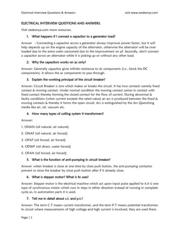
Wiring Diagrams (Continued)BLK BLU BRN GRNGRYORNPNK PUR RED TAN WHTYEL LIT DRK 1 - Vapor Separator Tank (VST)2 - Throttle Body3 - Distributor4 - Coil5 - Electronic Spark Control (ESC) Module6 - Assembly Line Data Link (ALDL)7 - Manifold Absolute Pressure (MAP) Sensor8 - Manifold Air Temperature (MAT) Sensor9 - Knock Sensor10 -Idle Air Control (IAC)11- Throttle Position Sensor (TPS)12 -Coolant Temperature Sensor (CTS)13 -Electronic Control Module (ECM)14 -Fuel Pump Relay)15 -Ignition Relay16 -Fuel Pump Fuse (15 Amp)17 -Injector Fuse(15 Amp)18 -ECM Fuse (10 Amp19 -Harness Connector to Starting/Charging Harness20 -Harness Connector to Lanyard Stop Switch (Optional)21 -Harness Connector for Dual Engine Data Link Cable22 -Positive ( ) Power Wire to Engine Circuit BreakerBlackBlueBrown Green Gray 110201361812517211519141622NOTE: All black wires with a ground symbol are interconnected within the EFI system harness.71692MCM (Stern Drive) –454/502 MAGNUM EFI ENGINE SYSTEM HA
EFI Wiring Diagram 4D-17. . . . . . . . . . . . . . . . . . . ECM Component Connector Charts 4D-21. . . . . . . 4D - WIRING DIAGRAMS. 90-806535940 893 WIRING DIAGRAMS - 4D-1 Wiring Colors for MerCruiser BIA Color Code Where Used Black All Grounds Brown Reference Electrode-MerCathode Orange Anode Electrode-MerCathode Lt. Blue/White Trim- ”Up” Switch Gray Tachometer Signal Green/White Trim .