Transcription
Technical Drawing اﻟرﺳــــــــم اﻟﮭــــــــــــﻧدﺳﻲ Dr. Anwar Abu-ZarifaDr. Anwar Abu-Zarifa . Islamic University Gaza . Industrial Engineering Department1
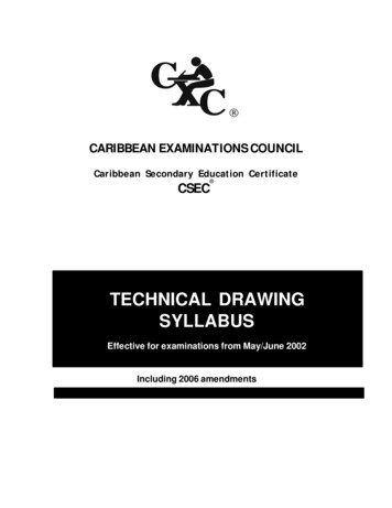
Office:IT Building, Room: I413Office Hrs: 12:00 – 13:00 (So, Tue, We)Text Book: BASIC OF ENGINEERING DRAWING, A. Abu-Zarifa, IUGReference Books: Reference Books:§Technical Drawing, Giesecke etc. , Prentice Hall, 13th Edition, 2008§Engineering Drawing And Design, Jensen ect., McGraw-Hill Science, 7th Edition, 2007§Fundamentals of Graphics Communication, Bertoline etc., McGraw-Hill, 6th Edition, 2010§Basic Technical Drawing, M.S. Samy Mousa, Maktabat El Yazji, 2000§Mechanical Design of Machine Elements and Machines, Collins ect., Wiley, 2 Edition, 2009Grading:Home worksMidtermFinal exam25%30%45%Dr. Anwar Abu-Zarifa . Islamic University Gaza . Industrial Engineering Department2
BASIC OF ENGINEERING DRAWING, A. AbuZarifa, IUGTechnical Drawing with EngineeringGraphics Frederick E.Technical Drawing (13th Edition)Frederick E. GieseckeDr. Anwar Abu-Zarifa . Islamic University Gaza . Industrial Engineering Department3
Unit 1Introduction to Technical DrawingDr. Anwar Abu-Zarifa . Islamic University Gaza . Industrial Engineering Department4
Engineers: People who use technical means to solveproblems. They design products, systems, devices, andstructures to improve our living conditions.Technical Drawings: a clear, precise language used in thedesign process for communicating, solving problems, quicklyand accurately visualizing objects, and conducting analyses. Agraphical representation of objects and structures is doneusing freehand, mechanical, or computer methods.Dr. Anwar Abu-Zarifa . Islamic University Gaza . Industrial Engineering Department5
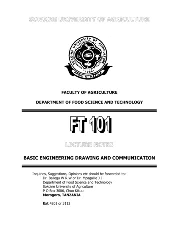
92% of the design process is graphical The remaining 8% is mathematics and written communicationBreakdown of Engineer’s timeWho uses engineering graphics?Dr. Anwar Abu-Zarifa . Islamic University Gaza . Industrial Engineering Department6
Development of Engineering GraphicsMultiview DrawingsFrancesca (1420-92)Dr. Anwar Abu-Zarifa . Islamic University Gaza . Industrial Engineering Department7
Artistic drawing vs. Technical drawingWhat’s the difference?Dr. Anwar Abu-Zarifa . Islamic University Gaza . Industrial Engineering Department8
Drawing ToolsTwo mechanical pencils:0.7 and 0.5 mm, or 0.5 and0.3 mm combinations;Pencil grades – HB and HOne compass and onedividerOne set of 45- and 30/60degree trianglesOne scales (Metric unit)and T-SquareOne protractorA3 Paper formatOne good eraser (and ifyou can afford, oneerasing shield)Dr. Anwar Abu-Zarifa . Islamic University Gaza . Industrial Engineering Department9
Drawing ToolsDr. Anwar Abu-Zarifa . Islamic University Gaza . Industrial Engineering Department
Dr. Anwar Abu-Zarifa . Islamic University Gaza . Industrial Engineering Department11
Alphabet of linesDr. Anwar Abu-Zarifa . Islamic University Gaza . Industrial Engineering Department12
Alphabet of lines cont.Dr. Anwar Abu-Zarifa . Islamic University Gaza . Industrial Engineering Department13
ScalesDr. Anwar Abu-Zarifa . Islamic University Gaza . Industrial Engineering Department14
Unit 2Geometric ConstructionsCompass and straightedge constructionsDr. Anwar Abu-Zarifa . Islamic University Gaza . Industrial Engineering Department15
Regular PolygonsDr. Anwar Abu-Zarifa . Islamic University Gaza . Industrial Engineering Department16
Dr. Anwar Abu-Zarifa . Islamic University Gaza . Industrial Engineering Department17
Dr. Anwar Abu-Zarifa . Islamic University Gaza . Industrial Engineering Department18
Dr. Anwar Abu-Zarifa . Islamic University Gaza . Industrial Engineering Department19
1.2.3.4.5.A regular pentagon has allsides of equal length andall interior angles are equalmeasure (108 )Bisect radius OD at CStrike arc AE, with C as center (Radius R)Stricke arc EB, with A as center (Radius r)Draw line ABSet of distances AB around the circumferenceDr. Anwar Abu-Zarifa . Islamic University Gaza . Industrial Engineering Department20
Dr. Anwar Abu-Zarifa . Islamic University Gaza . Industrial Engineering Department21
Dr. Anwar Abu-Zarifa . Islamic University Gaza . Industrial Engineering Department22
ANY REGULAR POLYGON in A GIVEN CIRCUMSCRIBED CIRCLEDr. Anwar Abu-Zarifa . Islamic University Gaza . Industrial Engineering Department
Dr. Anwar Abu-Zarifa . Islamic University Gaza . Industrial Engineering Department
Dr. Anwar Abu-Zarifa . Islamic University Gaza . Industrial Engineering Department25
Dr. Anwar Abu-Zarifa . Islamic University Gaza . Industrial Engineering Department
Dr. Anwar Abu-Zarifa . Islamic University Gaza . Industrial Engineering Department
اﻟﻘوس ﯾﻣس اﻟداﺋرة ﻣن اﻟداﺧل اﻟﻘوس ﯾﻣس اﻟداﺋرة ﻣن اﻟﺧﺎرج Dr. Anwar Abu-Zarifa . Islamic University Gaza . Industrial Engineering Department28
Dr. Anwar Abu-Zarifa . Islamic University Gaza . Industrial Engineering Department29
Dr. Anwar Abu-Zarifa . Islamic University Gaza . Industrial Engineering Department30
Unit 3Dimensioning FundamentalsDr. Anwar Abu-Zarifa . Islamic University Gaza . Industrial Engineering Department31
Dimensioning Orthographic and isometric views define the shape andgeneral features of the object Dimensioning adds information that specifies– Size of the object– Location of features (e.g. holes)– Characteristics of features (e.g. depth and diameter ofhole) Dimensions also communicate the tolerance (or accuracy)requiredDr. Anwar Abu-Zarifa . Islamic University Gaza . Industrial Engineering Department32
How are Objects Dimensioned? Objects are dimensioned based on twocriteria:– Basic size of the object and size and locationsof its features– Details of construction for manufacturing Defined Standards from ANSI (AmericanNational Standards Institute) existDr. Anwar Abu-Zarifa . Islamic University Gaza . Industrial Engineering Department33
Scaling vs. DimensioningDrawings can be different scales, but dimensions are ALWAYSat FULL scaleDr. Anwar Abu-Zarifa . Islamic University Gaza . Industrial Engineering Department34
Units of MeasureAngle Dimensions Length– English: Inches, unlessotherwise stated Up to 72" Feet and inches over 72"– SI: millimeter, mm Angle– degrees, minutes, secondsDr. Anwar Abu-Zarifa . Islamic University Gaza . Industrial Engineering Department35
Dimensioning – TerminologyDr. Anwar Abu-Zarifa . Islamic University Gaza . Industrial Engineering Department36
Text Height and StandardConfigurations.25 in.375 inDr. Anwar Abu-Zarifa . Islamic University Gaza . Industrial Engineering Department37
Dimensioning Basic Shapes Rectangular PrismDr. Anwar Abu-Zarifa . Islamic University Gaza . Industrial Engineering Department38
Dimensioning Basic ShapesPositive CylindersCylinders(solid)(hole)NegativeAvoid dimensioning tohidden linesDr. Anwar Abu-Zarifa . Islamic University Gaza . Industrial Engineering Department39
Dimensioning Basic Shapes Cone Do not overdimensionDr. Anwar Abu-Zarifa . Islamic University Gaza . Industrial Engineering Department40
Dimensioning Basic Shapes FrustumDr. Anwar Abu-Zarifa . Islamic University Gaza . Industrial Engineering Department41
Dimensioning Shows:A) SizeB) Location and OrientationDr. Anwar Abu-Zarifa . Islamic University Gaza . Industrial Engineering Department42
Principles of Good Dimensioning The overriding principle of dimensioning isCLARITY Principles – not an infallible rule set, needto apply good judgment. See 6.13 in Technical GraphicsDr. Anwar Abu-Zarifa . Islamic University Gaza . Industrial Engineering Department43
General Guidelines: Clarity is theGoal Place dimension in view that most clearlydescribes feature A view where a feature is hidden isgenerally NOT the most descriptive Avoid dimensioning to hidden lines.Dr. Anwar Abu-Zarifa . Islamic University Gaza . Industrial Engineering Department44
General Guidelines: Clarity is theGoal Dimension Outside of ViewAvoidGood PracticeDr. Anwar Abu-Zarifa . Islamic University Gaza . Industrial Engineering Department45
General Dimensioning Guidelines Start with basic outside dimensions of the object– Height– Width– Depth Add dimension for location and size of removed features Add general and specific notes – such as tolerancesDr. Anwar Abu-Zarifa . Islamic University Gaza . Industrial Engineering Department46
Practice ProblemHow many Dimensionsare needed?Dr. Anwar Abu-Zarifa . Islamic University Gaza . Industrial Engineering Department47
Practice ProblemHow many Dimensionsare needed?Answer: 8AU 2006Dr. Anwar Abu-Zarifa . Islamic University Gaza . Industrial Engineering Department48
Example DimensioningStep 1. Dimension basicoutside dimensions:1.004 HEIGHT4 WIDTH2.004 DEPTH1.25Dr. Anwar Abu-Zarifa . Islamic University Gaza . Industrial Engineering Department49
Practice ProblemGiven:Height: 2 mmWidth: 2 mmDepth: 1.5 mmHole Diameter: 1 mmDr. Anwar Abu-Zarifa . Islamic University Gaza . Industrial Engineering Department50
Practice ProblemΦ 1.0Dr. Anwar Abu-Zarifa . Islamic University Gaza . Industrial Engineering Department51
Unit 4Shap Description(Orthographic Projection)Dr. Anwar Abu-Zarifa . Islamic University Gaza . Industrial Engineering Department52
Even simple, primitiveshapes often needseveral views to fullydescribe their topology.Dr. Anwar Abu-Zarifa . Islamic University Gaza . Industrial Engineering Department53
Holes and cylinders may appear “True Shape and Size”(TSS), or foreshortened depending on the view in whichthey appear. (Foreshortened circles will appear as ellipses.)Dr. Anwar Abu-Zarifa . Islamic University Gaza . Industrial Engineering Department54
Dr. Anwar Abu-Zarifa . Islamic University Gaza . Industrial Engineering Department55
Orthographic ProjectionØOrthographic projection (sometimes referred to as multi-view projection),is a geometric procedure used in the engineering disciplines to projectmultiple graphic images of three-dimensional objects, onto a single twodimensional plane. The procedure is also called engineering drawing ordrafting, and is the primary means of communication used by designers andengineers in the design process.ØMultiple views in an orthogonal orientation (each rotated 90º from theother), is fundamental to the definition of feature and part characteristicssuch as size, location, orientation, and functional relationships.ØThe object can only be viewed from the front, top, right side, left side,back, or bottom. With the images indelibly fixed on the planes, and the boxunfolded, the projected images or views would always be orientedorthographically, and aligned with each other, from view to view on thedrawing.Dr. Anwar Abu-Zarifa . Islamic University Gaza . Industrial Engineering Department56
Ortho means “at90 degrees”, andis a form ofparallel projection.Orthographicprojections areused to showseveral views ofthe same object inone drawing set.Dr. Anwar Abu-Zarifa . Islamic University Gaza . Industrial Engineering Department57
Orthographic Projection TheoryObservation of an object begins with the direction from which the object is to beviewed—the line of sight.Dr. Anwar Abu-Zarifa . Islamic University Gaza . Industrial Engineering Department58
Orthographic Projection TheoryThe viewing station for the observer is always an infinite distance from the object. Viewing Stationat InfinityDr. Anwar Abu-Zarifa . Islamic University Gaza . Industrial Engineering Department59
Orthographic Projection TheoryThe plane of projection is located between the viewing station and the object (thirdangle projection).Line of Sight Viewing Stationat InfinityProjection Plane(Picture PlaneViewing Plane)Dr. Anwar Abu-Zarifa . Islamic University Gaza . Industrial Engineering Department60
Orthographic Projection TheoryThe line of sight is always normal to the plane of projectionLine of Sight Viewing Stationat InfinityProjection Plane(Picture PlaneViewing Plane)Dr. Anwar Abu-Zarifa . Islamic University Gaza . Industrial Engineering Department61
Orthographic Projection TheoryThe object may be located anywhere behind the plane of projectionObjectLine of Sight Viewing Stationat InfinityProjection Plane(Picture PlaneViewing Plane)Dr. Anwar Abu-Zarifa . Islamic University Gaza . Industrial Engineering Department62
Orthographic Projection TheoryBecause the observation location is at infinity, parallel visual rays extend from theobject to the plane of projection, and produce the image on the projection plane.ObjectLine of Sight Viewing Stationat InfinityParallel Visual RaysProjection Plane(Picture PlaneViewing Plane)Dr. Anwar Abu-Zarifa . Islamic University Gaza . Industrial Engineering Department63
GLASS BOX CONCEPTDr. Anwar Abu-Zarifa . Islamic University Gaza . Industrial Engineering Department
The glass box concept theorizes that an object is suspended inside a six-sided glass cube(notice the use of hidden lines on the glass box, depicting lines that would not be visiblefrom the given perspective).Dr. Anwar Abu-Zarifa . Islamic University Gaza . Industrial Engineering Department65
As the object is viewed from a specific orientation (perpendicular to one of the sides of the cube) visualrays project from the object to the projection plane. These projectors are always parallel to each other.Dr. Anwar Abu-Zarifa . Islamic University Gaza . Industrial Engineering Department66
The object’s image is formed on the Frontal projection plane by the pierce points of thevisual rays.Dr. Anwar Abu-Zarifa . Islamic University Gaza . Industrial Engineering Department67
The process is repeated to construct the right side view on the profile planeDr. Anwar Abu-Zarifa . Islamic University Gaza . Industrial Engineering Department68
Similarly, the top view is projectedto the horizontal planeDr. Anwar Abu-Zarifa . Islamic University Gaza . Industrial Engineering Department69
For many three-dimensional objects, two to three orthographic views are sufficientto describe their geometry.Dr. Anwar Abu-Zarifa . Islamic University Gaza . Industrial Engineering Department70
The box can be unfolded to show themultiple views in a single x-y planeDr. Anwar Abu-Zarifa . Islamic University Gaza . Industrial Engineering Department71
Because the observation point is located atinfinity, the integrity of feature size andlocation are maintained, and the views areoriented orthogonally in relationship to eachother.TOPFRONTRIGHT SIDEDr. Anwar Abu-Zarifa . Islamic University Gaza . Industrial Engineering Department72
Notice that the projectors or extension lines,are perpendicular to the folding lines of theglass box. (Fold lines and extension lines aredrawn very lightly, when used, and are not partof the finished drawing.)TOPFRONTRIGHT SIDEDr. Anwar Abu-Zarifa . Islamic University Gaza . Industrial Engineering Department73
Dimensional Data Can then be added to the drawingNotice the three basic line types: Solid – A Visible Edge Hidden - An Invisible Edge Center – Center of a Cylinder (Internal orExternal)Dr. Anwar Abu-Zarifa . Islamic University Gaza . Industrial Engineering Department74
The Glass Box ConceptClick on image to animate - click outside for next slideDr. Anwar Abu-Zarifa . Islamic University Gaza . Industrial Engineering Department75
ORIENTATION OF OBJECT FEATURES INORTHOGRAPHIC PROJECTIONDr. Anwar Abu-Zarifa . Islamic University Gaza . Industrial Engineering Department76
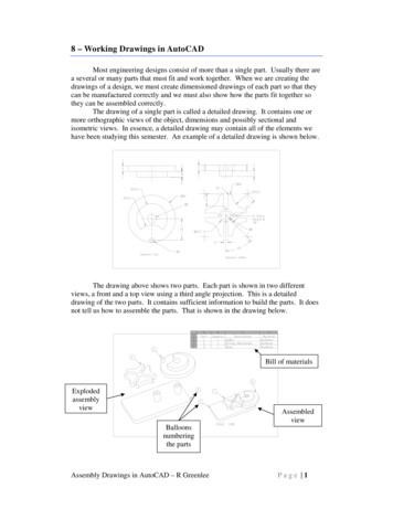
Directional Orientation in Orthographic ProjectionHeight hWidth wDepth dTOPTwo or three views of a 3-dimensionalobject are often sufficient for a completedefinition of part geometry. Width anddepth are displayed in the top view; heightand width in the front view, height anddepth in the side view.dwFRONTRIGHT SIDEwdhhDr. Anwar Abu-Zarifa . Islamic University Gaza . Industrial Engineering Department77
DIRECTION AND ORIENTATIONINORTHOGRAPHIC PROJECTION(PRINCIPAL PROJECTION PLANES)Dr. Anwar Abu-Zarifa . Islamic University Gaza . Industrial Engineering Department
FIRST-ANGLE PROJECTIONDr. Anwar Abu-Zarifa . Islamic University Gaza . Industrial Engineering Department79
Projection methods:3RD Angle (US Standard)ISO (1ST Angle Metric Standard)NOTE:Reverse construction methodswork just as well in 1ST Angleprojection.Dr. Anwar Abu-Zarifa . Islamic University Gaza . Industrial Engineering Department80
1st angle and 3rd angle Orthographics. The difference:Third-angle ProjectionFirst-angle ProjectionDr. Anwar Abu-Zarifa . Islamic University Gaza . Industrial Engineering Department81
Unit 5Creating Isometric SketchesDr. Anwar Abu-Zarifa . Islamic University Gaza . Industrial Engineering Department82
Introduction to IsometricProjection3CUBE4 Isometric means equal measure All planes are equally or proportionately shortened andtilted All the major axes (X, Y, Z) are 120 degrees apartDr. Anwar Abu-Zarifa . Islamic University Gaza . Industrial Engineering Department83
Making an Isometric Sketch Defining Axis60o60o30o30oIsometric AxisDr. Anwar Abu-Zarifa . Islamic University Gaza . Industrial Engineering Department84
Making an Isometric Sketch Axis ConventionHeightDepthWidthChoose the longestdimension to be thewidth or the depth foroptical stabilityIsometric Axis ConventionDr. Anwar Abu-Zarifa . Islamic University Gaza . Industrial Engineering Department85
Usage of the Grid PaperCorrect orientationIncorrect orientationNote the alignment of the axesDr. Anwar Abu-Zarifa . Islamic University Gaza . Industrial Engineering Department86
Object for PracticeDr. Anwar Abu-Zarifa . Islamic University Gaza . Industrial Engineering Department87
Blocking in the ObjectBegin with Front FaceHeightFront FaceWidthDr. Anwar Abu-Zarifa . Islamic University Gaza . Industrial Engineering Department88
Blocking in the Object: Add SideFaceSide FaceHeightDepthDr. Anwar Abu-Zarifa . Islamic University Gaza . Industrial Engineering Department89
Blocking in the Object: Add Top FaceTop FaceDr. Anwar Abu-Zarifa . Islamic University Gaza . Industrial Engineering Department90
Adding Detail Cut Outs – Part 1Dr. Anwar Abu-Zarifa . Islamic University Gaza . Industrial Engineering Department91
Adding Detail Cut Outs – Part 2Dr. Anwar Abu-Zarifa . Islamic University Gaza . Industrial Engineering Department92
Adding Detail Cut Outs – Part 3Dr. Anwar Abu-Zarifa . Islamic University Gaza . Industrial Engineering Department93
Darken Final Lines - Part 4Note:All visible edgeswill be darkenedDr. Anwar Abu-Zarifa . Islamic University Gaza . Industrial Engineering Department94
Isometric ellipses In an isometric drawing, the object isviewed at an angle, which makes circlesappear as ellipses. Holes CylindersAU 2006Dr. Anwar Abu-Zarifa . Islamic University Gaza . Industrial Engineering Department95
Ellipses Can be in Any of ThreePlanesDr. Anwar Abu-Zarifa . Islamic University Gaza . Industrial Engineering Department96
Sketching an Isometric CylinderDr. Anwar Abu-Zarifa . Islamic University Gaza . Industrial Engineering Department97
Four Center Method of Drawing an Isometric EllipseDr. Anwar Abu-Zarifa . Islamic University Gaza . Industrial Engineering Department
Dr. Anwar Abu-Zarifa . Islamic University Gaza . Industrial Engineering Department
Dr. Anwar Abu-Zarifa . Islamic University Gaza . Industrial Engineering Department
Unit 6Missing ViewsDr. Anwar Abu-Zarifa . Islamic University Gaza . Industrial Engineering Department101
3-D Sketch from a Multi-view Drawing with Missing ViewConstruction the third View (Missing View)Construction Isometric Sketches from Ortho ViewsDr. Anwar Abu-Zarifa . Islamic University Gaza . Industrial Engineering Department
Isometric GridMissing ViewsSquare GridGiven the frontand right sideview, determinethe top andisometric views.Dr. Anwar Abu-Zarifa . Islamic University Gaza . Industrial Engineering Department
?Step 1Create theOutline (Box)for IsometricViewDr. Anwar Abu-Zarifa . Islamic University Gaza . Industrial Engineering Department
?Step 2Draw knownsurfaces ofIsometric viewDr. Anwar Abu-Zarifa . Islamic University Gaza . Industrial Engineering Department
?Step 2 (contd)Draw knownsurfaces ofIsometric viewDr. Anwar Abu-Zarifa . Islamic University Gaza . Industrial Engineering Department
?Step 2 (contd)Draw knownsurfaces ofIsometric viewDr. Anwar Abu-Zarifa . Islamic University Gaza . Industrial Engineering Department
?Step 2 (contd)Draw knownsurfaces ofIsometric viewDr. Anwar Abu-Zarifa . Islamic University Gaza . Industrial Engineering Department
?Step 3FinalizeIsometric ViewDr. Anwar Abu-Zarifa . Islamic University Gaza . Industrial Engineering Department
ADDING TOP VIEWStep 4AAdd OutsideBoundary(width and depth fromfront and right sideviews)Dr. Anwar Abu-Zarifa . Islamic University Gaza . Industrial Engineering Department
ADDING TOP VIEWStep 4BAdd Visible Lines(for the Steps)Dr. Anwar Abu-Zarifa . Islamic University Gaza . Industrial Engineering Department
Step 4CAdd Hidden LineDr. Anwar Abu-Zarifa . Islamic University Gaza . Industrial Engineering Department
Dr. Anwar Abu-Zarifa . Islamic University Gaza . Industrial Engineering Department
Unit 7Sectional ViewsDr. Anwar Abu-Zarifa . Islamic University Gaza . Industrial Engineering Department114
Section Views Section views are used whenimportant hidden details arein the interior of an object. These details appear ashidden lines in one of theorthographic principal views;therefore, their shapes arenot very well described bypure orthographic projection.Dr. Anwar Abu-Zarifa . Islamic University Gaza . Industrial Engineering Department115
Types of Section Views Full sectionsHalf sectionsOffset sectionsBroken-out sectionsRevolved sectionsRemoved sectionsDr. Anwar Abu-Zarifa . Islamic University Gaza . Industrial Engineering Department116
Cutting Plane Section views show how an object would look if acutting plane (or saw) cut through the object andthe material in front of the cutting plane isremovedDr. Anwar Abu-Zarifa . Islamic University Gaza . Industrial Engineering Department117
Section Lines Section lines can be usedto show different types ofmaterials or different partsof the same material. Refer to TechnicalGraphics text for acomplete listDr. Anwar Abu-Zarifa . Islamic University Gaza . Industrial Engineering Department118
Full Section View In a full section view,the cutting planecuts across theentire object Note that hiddenlines become visiblein a section viewDr. Anwar Abu-Zarifa . Islamic University Gaza . Industrial Engineering Department119
Full Section View Show cutting plane in the top viewMake a full section in the front viewNote how the cutting plane is drawn and how the crosshatching lines markthe surfaces of material cut by the cutting plane.Dr. Anwar Abu-Zarifa . Islamic University Gaza . Industrial Engineering Department120
Full Section View No hidden lines onthe section view, ifpossible. Note: Interior linesbehind cutting planebecame visible.Dr. Anwar Abu-Zarifa . Islamic University Gaza . Industrial Engineering Department121
Dr. Anwar Abu-Zarifa . Islamic University Gaza . Industrial Engineering Department122
Multiple Sectioned ViewsNote the directionsof arrows on the cutting plane.SECTION A-ABASECTION B-BABDr. Anwar Abu-Zarifa . Islamic University Gaza . Industrial Engineering Department123
Half Section View The cutting planes donot cut all the waythrough to the object. They cut only half wayand intersect at thecenterline.Dr. Anwar Abu-Zarifa . Islamic University Gaza . Industrial Engineering Department124
Half Section ViewHalf Section usedmainly forsymmetric objectsDr. Anwar Abu-Zarifa . Islamic University Gaza . Industrial Engineering Department125
Offset SectionsOffset sectionsare used to showinterior featuresthat do not liealong a straightlineDr. Anwar Abu-Zarifa . Islamic University Gaza . Industrial Engineering Department126
Offset SectionsDr. Anwar Abu-Zarifa . Islamic University Gaza . Industrial Engineering Department127
Offset SectionsAU 2005Dr. Anwar Abu-Zarifa . Islamic University Gaza . Industrial Engineering Department128
Name the Three Types of Sections Full Section (half of the object is removed) Half Section (a quarter of the object isremoved) Offset Section (the cutting plane line is drawnto pick up an object's features)Dr. Anwar Abu-Zarifa . Islamic University Gaza . Industrial Engineering Department129
Broken Out SectionsA broken-outsection view iscreated bybreaking offpart of theobject to revealinterior featuresDr. Anwar Abu-Zarifa . Islamic University Gaza . Industrial Engineering Department130
Broken OutSectionsHidden lines are used onlywhen needed for clarity.Dr. Anwar Abu-Zarifa . Islamic University Gaza . Industrial Engineering Department131
Revolved SectionsA Revolvedsection iscreated bypassing acutting planethrough theobject, thenrevolving thecross section 90degreesDr. Anwar Abu-Zarifa . Islamic University Gaza . Industrial Engineering Department132
Revolved SectionsRevolved sectionsshow the shape ofan object's crosssectionsuperimposed on alongitudinal viewDr. Anwar Abu-Zarifa . Islamic University Gaza . Industrial Engineering Department133
Revolved Sections – TubesDr. Anwar Abu-Zarifa . Islamic University Gaza . Industrial Engineering Department134
Revolved Sections – I BeamDr. Anwar Abu-Zarifa . Islamic University Gaza . Industrial Engineering Department135
Removed SectionsA removedsection view iscreated bymaking a crosssection, thenmoving it to anarea adjacent tothe view.Dr. Anwar Abu-Zarifa . Islamic University Gaza . Industrial Engineering Department136
Removed SectionsA Removed sectionsare like revolvedsections but movedaside.Section B-BASection A-ABB Note how they arenamed.Section C-CCCDr. Anwar Abu-Zarifa . Islamic University Gaza . Industrial Engineering Department137
Unit 7Introduction to AutoCadDr. Anwar Abu-Zarifa . Islamic University Gaza . Industrial Engineering Department138
OUTLINE Giving commandsObject snapZooming and panningDrawing 2D shapesDrawing 3D shapesEditingDr. Anwar Abu-Zarifa . Islamic University Gaza . Industrial Engineering Department
How do we give a command? Command line Toolbars(view/Toolbars) Drop-down menusYou can pick any one(s) that you are comfortable with.Dr. Anwar Abu-Zarifa . Islamic University Gaza . Industrial Engineering Department
Dr. Anwar Abu-Zarifa . Islamic University Gaza . Industrial Engineering Department
What is OSNAP? Osnap (Object Snap) settings make it easier to select a 2dobject’s Centerİntersection Osnap will be active whenAutoCAD is expecting you topick a point on the working area Type osnap on yourcommand window:Dr. Anwar Abu-Zarifa . Islamic University Gaza . Industrial Engineering Department
Zooming. You will need to zoom in and out while drawing withAutoCAD. This doesnt change your objects or UCS, only theway you see your working space. This can be done in manyways:1.2.Scroll barsTyping z or zoom in your command window. All Center Dynamic Extents Previous Scale WindowDr. Anwar Abu-Zarifa . Islamic University Gaza . Industrial Engineering Department
Lets draw a LINE: remember that AutoCAD recognizes an object by itscoordinates. You will need two given points to draw aline.(x2,y2,z2)(x1,y1,z1) You can start at a random point on your WCS for yourFIRST POINT, but you should specify the coordinates ofyour SECOND POINT.Dr. Anwar Abu-Zarifa . Islamic University Gaza . Industrial Engineering Department
Lets draw a LINE (1):ba301. Give the command–––Type “line” on the command window, ORClick on the line icon on the Draw toolbar, ORSelect Line on the Draw menu2. Specify the first point (a)–Click on a random point on your working area (black space)3. Specify the second point in relation to the first point––@distance degrees@5 30Dr. Anwar Abu-Zarifa . Islamic University Gaza . Industrial Engineering Department
Lets draw a LINE (2):a1.2.3.4.7 unitsbHit F8 (ortho on)Give the commandSpecify the first pointSpecify the second point in relation to the first point––Point the cursor to the left hand side. You will see that thecursor snaps only to 0o-90o-180o-270oType 7 and hit enterDr. Anwar Abu-Zarifa . Islamic University Gaza . Industrial Engineering Department
Lets draw a LINE (3):a(4,8,11)b(5,22,13)If we know the coordinates of the line we want to draw,we can simply type them into the command line.(However, this mostly is not the case.)1. Give the command2. Specify the first point (4,8,11)3. Specify the second point (5,11,23)Dr. Anwar Abu-Zarifa . Islamic University Gaza . Industrial Engineering Department
What else?a Rectangle: two diagonal lines(pick first point, select the second one withrelation to the first. @5 -33) Circle/Arc: center and radiusbda Polygon: specify the number of edges andlength of a sidedA small tip: you can use the EXPLODE command for the tool to splitthe object into its components or linesDr. Anwar Abu-Zarifa . Islamic University Gaza . Industrial Engineering Department
Editing COPYo ARRAY MOVEo SCALE MIRRORo STRETCHDr. Anwar Abu-Zarifa . Islamic University Gaza . Industrial Engineering Department
More editing o OFFSET STRETCHo ROTATE EXPLODEo ERASEDr. Anwar Abu-Zarifa . Islamic University Gaza . Industrial Engineering Department
Hatching Hatching is used to add shaded patterns to objects and shapes within anAutocad drawing. Hatch patterns can be used to indicate a material to beused, such as a concrete hatch. Alternatively it could be used to make anarea of a drawing stand out. You will pick:––––PatternScaleAnglepointsDr. Anwar Abu-Zarifa . Islami
§Fundamentals of Graphics Communication, Bertolineetc., McGraw-Hill, 6th Edition, 2010 . Technical Drawing (13th Edition) Frederick E. Giesecke Technical Drawing with Engineering Graphics Frederick E. BASICOFENGINEERINGDRAWING,A.Abu-Zar