Transcription
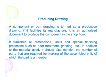
Producing DrawingA component or part drawing is termed as a productiondrawing, if it facilities its manufacture. It is an authorizeddocument to produce the component in the shop floor.It furnishes all dimensions, limits and special finishingprocesses such as heat treatment, grinding, etc., in additionto the material used. It should also mention the number ofparts that are required for making of the assembled unit, ofwhich the part is a member.
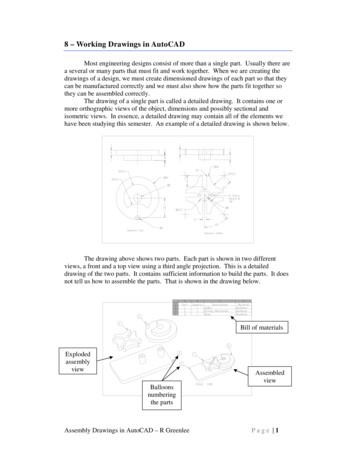
Production drawing of a component should also indicatethe sub or main assembly where it will be assembled. It isnecessary to prepare the production drawing of eachcomponent on a separate sheet, since a craftsman willordinarily make one component at a time. However, insome cases, the drawings of related components mayalso appear on the same sheet. Figure 1.2 shows theproduction drawing of a jig bush.
Fig. 1
Need for a production drawingThe graphic representation of a product, starts at thetransformation stage of ideas into a drawing by a designengineer. A production drawing is a complete workingdrawing, representing all the details of the product, regardingsize, shape, material, process, tools and equipment.The craftsman is completely guided by the productiondrawing, during the manufacture of the product. Hence, anymistake in a production drawing will result in loss of time,money and decreased productivity. Further, it is a legaldocument while going for subcontracting of works. Hence, aproduction drawing should be prepared without any scope formore than one interpretation.
The design engineer uses orthographic or pictorialviews to record his ideas, free hand. These arecalled working sketches. These sketches are usedfor both the component and assembly drawings.The working drawings are sent to the shop, in theform of blue prints, ammonia prints or other similarforms of reproduction. Therefore, the drawings mustbe made as tracings.
Elements of production drawingFollowing are the basic elements of a production drawing.1. Format of drawing sheet,2. Size and shape of the component,3. Projection method,4. Material specification and shape such as castings,forgings, plates, rounds, etc.,5. Indication of surfacetreatments, if any,roughnessandotherheat
6. Limits, fits and tolerances of size, form, and position,7. Production method,8. Process sheet,9. Specification of standard components,10. Conventions used to represent certain machinecomponents, and11. Inspection and testing methods.
Drawing Sheet SizesDrawing paper and cloth are available in rolls of variouswidths and in standard trimmed sizes. Most of thedraughting rooms use standard sheets, printed withborder and title block. There are five standard sizes fordrawing sheets (First choice), specified by Bureau ofIndian Standards (BIS) SP: 46-1988, as given below. Thestandard sizes help save paper and are also convenientfor storing.
DesignationA0Dimension (mm)841 X 1189A1594 X 841A2420 X 594A3297 X 420A4210 X 297Drawing sheets may be used with their longer sidespositioned horizontally or vertically. The original drawingshould be made on the smallest sheet, permitting thenecessary clarity and resolution.
Drawing sheet layoutThe layout of a drawing sheet should, by the clarity andneatness of its appearance, facilities the reading of thedrawing. It should also facilitate essential references to belocated easily.Borders, enclosed by the edges of the trimmed sheet and theframe, limiting the drawing space shall be provided with allthe sheet sizes. It is recommended that these borders have aminimum width of 20 mm for the sizes A0 and A1 and aminimum width of 10 mm for other sizes. A file margin fortaking perforations may be provided on the edges, far left ofthe title block. It should have a minimum width of 20 mm.
Four centering marks shall be provided in order to facilitatepositioning of the drawing, when reproduced or microfilmed.Two orientation marks may be provided to indicate theorientation of the drawing sheet on the drawing board.It is recommended to provide on all drawings, a figurelessmetric reference graduation, with minimum length of 100mm and divided into 10 equal parts. The metric referencegraduation shall preferably be disposed symmetrically aboutthe centring mark, near the frame in the border, with aminimum width of 5 mm.
The provision of the grid reference system (zoning) isrecommended for all sizes, in order to permit easy location onthe drawing, of details, additions, modifications, etc. Thenumber of divisions should be even and be chosen in relationto the complexity of the drawing. However, the length of anyside of the rectangle shall be from 25 to 75 mm. Therectangles of the grid should be referenced by means ofcapital letters along one edge and numerals along the other.The numbering direction may start at the sheet corner,opposite to the title block and be repeated on the oppositesides.The trimming marks may be provided in the borders, at thefour comers of the sheet in order to facilitate trimming. Thesemarks may be in the form of right angled isosceles triangles.
The pre-printed drawing sheets when used, should includethe following features:1. Title block,2. Frame for limiting the drawing space,3. Centring marks, and4. Optional features:i) metric reference graduation, ii) grid referencesystem, and iii) trimming marks.
Fig. 2 represents a typical layout of a drawing sheet.Fig. 2
Title blockThe drawing sheet layout must also provide a title block,which should be located at the bottom right hand corner ofthe sheet; both for sheets positioned horizontally orvertically, with a maximum length of 170 mm. This shouldprovide the following basic information:
1. Title of the drawing,2. Sheet number,3. Scale (s),4. Symbol, denoting the method of projection,5. Name of the firm, and6. Initials of the staff designed, drawn, checked and approved.The direction of viewinggeneral, with that of theblock is shown in Fig. 3.block may be arrangedoverall size specified.the title block should correspond indrawing. A typical layout of the titleHowever, the heading inside the titleas per the convenience, within the
A production drawing may include the followingadditional information, located either in the drawingsheet or in the title block:1. Job order number,2. Surface treatment, roughness, etc.,3. Key to machining and other symbols,4. A general note on tolerance on dimensions, notindividually toleranced,5. Reference to tools, gauges, jigs and fixtures,6. Parts list, and7. Alternations and revisions.
Fig. 3
Information on a drawingEvery drawing should be numbered. Some companies useserial numbers such as 70524 or a number with prefix orsuffix, K2-70524 or 70524-K2. Many different numberingsystems are in use, in which various digits of the drawingnumbers indicate different things, such as model number ofthe machine and the general nature or use of the part.If all the drawings are made to the same scale, the scaleshould be indicated in or near the title block. Otherwise, theindividual scales should be indicated below the respectivedrawings.
General notes can be given on the working drawings tospecify the tolerances of dimensions.According to the BIS SP:46-1988, Engineering drawingpractice for schools and colleges; first angle projectionmethod only, is required to be followed.Specifications regarding general notes, material, heattreatment, finish, general tolerances and number requiredare located on or near the title block.
Notes should always be letteredhorizontally in capital letters andbegin above the leader line and mayend below also. Further, notesshould be brief and clear and thewording should be standard in formas shown in Fig. 3.42. The meaningof the notes in each case is givenbelow:
Standard abbreviations Standard abbreviations in draughting arerecommended as notes to provide a briefand clear instructions. Table 3.1 providesthe draughting abbreviations for generalterms, Table 3.2 represents s for rolled sections of steel.
Principles of DimensioningIntroductionA detail drawing is expected to provide not only thecomplete shape description of the part, but also furnish sizedescription. This is provided in the form of distance betweenthe surfaces, location of holes, kind of finish, type ofmaterial, etc. These features are illustrated on a drawing bythe use of lines, symbols, figures, and notes, calleddimensioning. Proper dimensioning requires engineeringjudgment and thorough knowledge of the practices andrequirement of the production department. Dimensions areclassified into the following types:
1. Functional dimension (F) – A dimension that is essentialto the function of the part.2. Non functional dimension (NF) – A dimension that is notessential to the function of the part.3. Auxiliary dimension (AUX) – A dimension given forinformation purpose only. It does not govern theproduction or inspection operations and is derived fromother values shown on the drawing. An auxiliarydimension is enclosed in parenthesis and no toleranceapplies to it.
Figure 1 indicates the classification of dimensionsFig. 1 Classification of dimensions
Principles of DimensioningThe following are the basic principles of dimensioning:1. All dimensional information necessary to define a partclearly and completely shall be shown directly on adrawing, unless this information is specified in associateddocumentations.2. Each feature shall be dimensioned once only on adrawing.3. Dimensions shall be placed on the view or section thatshows clearly, the corresponding features (Fig. 2).
Fig. 2 Placement of dimensionswhere the shape is best shown
4. As far as possible, on a drawing, dimensions should beexpressed in one unit only, preferably in millimeters,without showing the unit symbol (mm). Unit on thedrawing, however, may be shown in a note (Fig. 9).5. No more dimensions than are necessary to define a partshall be shown on the drawing. No feature of a part shallbe defined by more than one dimension in any onedirection (Fig. 3).
Fig. 3 Placement of only necessary dimensions
6. As far as possible, dimensions should be placed outsidethe view (Fig. 4).Fig. 4 Placement of dimensions outside the view
7. Dimensions should be represented from the visibleoutlines, rather than from hidden lines (Fig. 5).Fig. 5 Marking of dimensions from the visible outlines
8. Dimensions should be given from a base line, a centre lineof a hole, or a finished surface. Dimensioning to a centreline should be avoided, except when it passes through thecenter of a hole (Fig. 6).Fig. 6 Avoiding dimensioning to the centre line
9. Interesting projection and dimension lines should beavoided. Were unavoidable, however, neither line shouldbe shown with a break (Fig. 7a). Dimension line shouldnot be used as an extension line (Fig. 7b).A centre line or the outline of a part should not be used as adimension line, but may be used in place of a projection line(Fig. 7c); where centre line is used as a projection line, itmay be continued as a centre line.
Fig 7
10. If the space of dimensioning is insufficient, the arrowheads may be reversed and the adjacent arrow headsmay be replaced by a dot (Fig. 8).Fig. 8 Dimensioning in narrow spaces
Execution of DimensionsThe elements of dimensioning include theprojection line, dimension line, leader line,dimension line origin indication, its termination,notes, the dimension, etc. The various elementsof dimensioning are shown in Fig. 9.
Fig. 9 Elements of dimensioning
Projection and dimension lines should be drawn as thincontinuous lines. Projection lines should extend slightlybeyond the respective dimension line. It should beperpendicular to the feature being dimensioned. Wherenecessary, however, they may be drawn obliquely, butparallel to each other in special cases, such as on taperedfeatures (Fig. 10).Fig. 10 Dimensioning a tapered feature
A leader line is a line referring to a feature (dimension,object, outline, etc.). Leader lines should terminate (Fig. 11).Fig. 11 Termination of leader lines
i. with a dot, it they end within the outline of an object,ii. with an arrow head, if they end on the outline of an object,iii. without dot or arrow head, if they end on a dimension line.Leader lines should be included to the horizontal at anangle greater than 30.
Fig. 12 Dimensioning several arcsFig. 13 Unbroken dimension line
When several arcs are dimensioned, it is preferable thatseparate leaders be used rather than extending the leaders(Fig. 12).A dimension line should be shown unbroken, even where thefeature to which it refers is shown broken (Fig. 13).Dimension lines should show distinct termination, in the formof an arrow heads or oblique strokes or where applicable, anorigin indication (Fig. 14). The size of the termination shouldbe proportionate to the size of the drawing on which it is used.One style of termination only should be used on a singledrawing. However, where space is too small for an arrowhead, the oblique stroke or a dot may be substituted.
Fig. 15 Dimensioning of radii
Only one arrow head termination, with its point on the arcend of the dimension line, is to be used where a radius isdimensioned (Fig.15).The arrow head termination may beeither on the inside or on the outside of the feature outline,depending upon the size of the feature. Dimensions shouldbe written on a drawing, according to one of the following twomethods. Only one method should be used on any onedrawing.Aligned systemDimensions should be placed parallel to the dimension linesand preferably near the middle, above and clear off thedimension line (Fig. 16a). An exception may be made wheresuperimposed running dimensions are used (Fig. 16b).
Fig. 16 Aligned dimensioning
Dimensions should be written, so that they may be readfrom the bottom or from the right side of the drawing.Dimensions on oblique dimension lines should be orientedas shown in Fig. 17.Angular dimensions may be oriented as shown in Fig. 18.Fig. 17 Oblique dimensioningFig. 18 Angular dimensioning
Uni-directional systemDimensions should be written so that they may be read fromthe bottom of the drawing. Non-horizontal dimension linesare interrupted, preferably near the middle, for the insertionof the dimension (Fig. 19).Angular dimensions may be oriented as shown in Fig. 20.
Fig. 19 Unidirectional dimensioning Fig. 20 Angular dimensioning
The placing of dimensions frequently needs adopting tovarying situations. For example, dimensions may be,i. closer to a termination, to avoid having to follow a longdimension line, where only part of the dimension lineneeds to be shown (Fig. 21).ii. above the extension of the dimension line, beyond one ofthe terminations, at the end of a leader line whichterminates on a dimension line; above a horizontalextension of dimension line where space does not allowplacement (Fig. 8).
Dimensions out-of-scale (except where break lines are used)should be underlined with a straight thick line (Fig. 22), wherefeature size modification does not warrant an extensivedrawing revision, to correct the feature scale.Fig. 21 Dimensioning closer to termination Fig. 22 Indication of out-of-scale dimension
Arrangement of dimensionsThe arrangement of dimensions on a drawing mustindicate clearly the design purpose. Generally, it is theresult of a combination of various design requirements.Chain dimensioningThis consists of chains of simple dimensions being usedwhere the possible accumulation of tolerances does notendanger (Fig. 23) the functional requirement of the part.
Fig. 23 Chain dimensioning
Parallel dimensioningThis consists of placement of a number of single dimensionlines, parallel to one another and spaced to write thedimension easily (Fig. 24). Superimposed runningdimensioning may be used (Fig. 16b) where there are spacelimitations.Fig. 24 Parallel dimensioning
Dimensioning from a common feature may be executed asparallel dimensioning or as superimposed runningdimensioning.Combined dimensioningSingle dimensions, chain dimensioning and dimensioningfrom a common feature may be combined on a drawing (Fig.25).Fig. 25 Combined dimensioning
The dimension figures should be placed approximately at thecentre of the dimension line, but the dimension figures inparallel dimensioning should be staggered (Fig. 26).Fig. 26 Staggering dimensions
Where an over-all dimension is shown, the intermediatedimension is redundant and need not be shown (Fig. 27).Fig. 27 Redundant dimensions
The first row of dimensions should be placed atleast 10 mmfrom the view and the successive rows should be atleast 6 mmfrom the first row (Fig. 28).Dimension figures should not be placed over the lines ofsectioned areas unless necessary; in which case, clear spaceshould be provided for the dimension figures (Fig. 29).Fig. 28 Spacing of dimensions Fig. 29 Dimensioning sectioned areas
Angles are dimensioned with arcs and extension lines, andthe dimension should not be placed inside the angle cut(Fig. 30).Fig. 30 Dimensioning an angle
Dimensions of lengths and relevant diameters should begiven in the same view in the drawing as far as possible(Fig. 31).Fig. 31 Dimensioning lengths and related diameters
Dimensions which go together, for example, the diameterand depth of a hole, the width and length of a groove,should be entered in the same view as far as practicable(Fig. 32).Dimensioning by co-ordinatesThe sizes of the holes and their co-ordinate dimensionsmay be indicated directly on the drawing or they may beconveniently presented in a tabular form as shown in Fig.33.
Fig. 32 Dimensioning a holeFig. 33 Co-ordinate dimensioning
Special IndicationsIn addition to the features being dimensioned; the nature ofthe feature may also be reflected while dimensioning, forenhanced clarity of the detail.Fig. 34 Shape identification symbols
Shape identification symbolsSymbols are used with dimensions to indicate shapeidentification, thus improving drawing interpretation. Theapplicable indication (symbol) should precede the dimension(Fig. 34).DiametersDimensions of diameters should be placed on the mostappropriate view to ensure clarity and should be preceded bythe symbol Ø in order to distinguish the diameter from alength. Figure 35 indicates the method of dimensioningdiameters.
Fig. 35 Dimensioning diameters
When centre lines cross each other in a view, at theintersection point, the longer dashes only should beintersected symmetrically (Fig. 36).Fig. 36 Centre lines at the crossing points
Chords, arcs, angles and radiiDimensions of chords, arcs and angles should be as shownin Fig. 37.Fig. 37 Dimensioning of chords, arcs and angles
Where the centre of an arc falls outside the limits of thespace available, the dimension line of the radius shouldbe broken or interrupted, according to whether or not it isnecessary to locate the centre (Fig. 15).Where the size of the radius can be derived from otherdimensions, it shall be indicated with a radius arrow andthe symbol R, without an indication of the value.Equidistant featuresWhere equidistant features or uniformly arranged elementsare part of the drawing specification, dimensioning maybe simplified as follows:1. Linear spacings may be dimensioned as shown in Fig. 38(one space may be dimensioned to avoid possibility ofconfusion).
Fig. 38 Dimensioning equidistant features
2. Angular spacing of holes and other features may bedimensioned as shown in Fig. 39.Fig. 39 Dimensioning equispaced angular feature
Chamfers and counter-sinksChamfers may be dimensioned as shown in Fig. 40, andcounter-sinks, as shown in Fig. 41.Fig. 40 Dimensioning champers
Fig. 41 Dimensioning counter-sinks
Tapered featuresTapered features are dimensioned, either by specifying thediameters at either end and the length, or the length, one ofthe diameters and the taper or taper angle (Fig. 42a).A slope or flat taper is defined as the rise pr unit length and isdimensioned by the ratio of the difference between the heightsat the ends to its length (Fig. 42b).
Fig. 42 Dimensioning tapered features
Screw threadsScrew threads are always specified with proper designation.The nominal diameter is preceded by the letter M. The usefullength of the threaded portion should be dimensioned asshown in Fig. 43. While dimensioning the internal threads,the length of the drilled hole should also be dimensioned.
Fig. 43 Dimensioning screw threads
KeywaysDimensioning of keyways, both external and internal, isfollowed as shown in Fig. 44. Figure 44a shows themethod of dimensioning, as recommended for the keywayon a shaft, located at its end and Fig. 44b, for keywaylocated at some intermediate position. Figure urement of the given dimensions.
Fig. 44 Dimensioning keyways
Spherical featuresFigure 45 represents correct and incorrect method ofdimensioning a spherical feature. Here too, the dimensioningrequirement is measurement feasibility.Fig. 45 Dimensioning spherical features
Quality ControlIn the bygone era, quality control consisted of inspection ofgoods produced and finally picking the good ones. Later itwas realized that during the manufacture, the products(semi-finished or unfinished) could be inspected so that thefinal quality cost may be reduced.
This leads to what is called total quality control and Kaizenapproach to quality maintenance. International organizationfor standards (ISO), Geneva comprising of representation byover 100 countries, set up a technical committee for qualitymanagement and quality assurance. System standards werefinalized and released as ISO-9000 series in 1987. Thesestandards aim to document/implement company wide qualityassurance programmes that lead to certain level ofconsistency in product service characteristics. Theseporgrammes are bottom-up programmes involving everyindividual, unlike earlier top-down procedures. They aremeant not just to control product quality, but to maintain itsuniformity and predictability.
An organization, should attempt to fulfil the following whileaiming to adopt ISO-9000:a) to improve customer satisfaction,b) to increase competitiveness,c) to reduce the cost of quality.Any organization, production/service oriented, has to setup ashort or long term implementation programme byconstituting a steering committee chaired by a seniorexecutive. This committee is responsible for coordinatingquality improvement process activities through the plantfunctions.
Definition of ISO-9000 seriesISO-9000 is the most comprehensive model for ion,installation and service. This comprises of four series.ISO-9001 is a quality system model for quality assurance indesign/development, production and installation.
ISO-9002 is a quality system model for quality assurancein production and installation.ISO-9003 is a quality system model for quality assurancein final inspection test.ISO-9004 is a quality system model for qualitymanagement and quality system elements and guidelines.
Why ISO certification?Company may not be able to export its products withoutISO-9000.Streamlining of operations and control of waste, rework,etc. is the byproduct impact (direct cost reductionbenefits).ISO 9000 is a powerful marketing weapon. Theorganization will have an edge over other suppliers indomestic market also.
It is a credibility passport which says that the companymeets international standards in designing/developing,producing, installing and service the products it supplies.ISO-9000 facilities mutual recognition of any product legallyproduced or marketed in one country to be accepted inprinciple in a another country.ISO-9000 series registration lays the foundations on whichwise management must relentlessly improve to become andremain customer sensitive, high quality and low costcompany.
IS 14000The member countries when adopt the ISO-9000 series,different numbers are given to the quality models. Whenthe Bureau of Indian Standards implemented ISO-9000series in toto, the standards are in family of IS-14000 withIS-4001 to Is-4004.For a quality consciousness, any organization whetherproduction/service oriented, should document theprocedures used and get them audited and inspected atregular intervals whether the aim is to get the certificationor not.
transformation stage of ideas into a drawing by a design engineer. A production drawing is a complete working drawing, representing all the details of the product, regarding size, shape, material, process, tools and equipment. The craftsman is completely guided by the production drawing, during the manufac