Transcription
8 – Working Drawings in AutoCADMost engineering designs consist of more than a single part. Usually there area several or many parts that must fit and work together. When we are creating thedrawings of a design, we must create dimensioned drawings of each part so that theycan be manufactured correctly and we must also show how the parts fit together sothey can be assembled correctly.The drawing of a single part is called a detailed drawing. It contains one ormore orthographic views of the object, dimensions and possibly sectional andisometric views. In essence, a detailed drawing may contain all of the elements wehave been studying this semester. An example of a detailed drawing is shown below.The drawing above shows two parts. Each part is shown in two differentviews, a front and a top view using a third angle projection. This is a detaileddrawing of the two parts. It contains sufficient information to build the parts. It doesnot tell us how to assemble the parts. That is shown in the drawing below.Bill of numberingthe partsAssembly Drawings in AutoCAD – R GreenleePage 1
Note: The assembly views in the drawing above are shown asisometric or pictorial views. This is usually not done inAutoCAD drawings. AutoCAD assembly views are usuallyorthographic because of the difficulty in drawing pictorialviews.The Bill of Materials (BOM) lists all of the parts needed to make the machine.Each part is numbered in the BOM and the same number is used in the balloons thatpoint to each part. The bill of materials lists the part number, the name of the part,and the material from which the part is made.Both exploded and unexploded assembly views are shown in this particularexample but if the assembly can be fully explained with a single view, then only oneview need be shown. The view may be similar to one of the ones in the drawingabove or it may be a sectional view. Sectional assembly views are especially useful ifsome parts are inside of housings or are concealed from view.A set of working drawings consists of a detailed drawing for each part thatmust be manufactured and sufficient assembly drawings to explain how the parts areassembled.Detailed DrawingsThe first step in creating a set of working drawings is to create the detaileddrawings showing each part. Here you usually show a front view and possibly otherviews (top view, right side view, left side view, etc.) if they are required to fullydescribe the geometry. Sectional views and isometric views may also be included ifthe geometry is not easily understood from the orthographic projections. Dimensionsare included on these drawings so the part can be manufactured correctly. The titleblock on the drawing should contain the name of the part and this should be the samename used in the Bill of Materials.After the detailed views are drawn, you can create the assembly drawings.These drawings are created by combining views from the detailed drawings to showhow the parts are assembled. The process involves several simple steps.1. First you need to create the assembly drawing. You can do this by opening theStandard A4 drawing sheet (You may have named it differently.) Once it isopen, remember to use “Save as” to save the drawing under a different name.I usually use the abbreviation “ ASM” as the last characters in the file nameso that I will know that this is an assembly drawing.2. Open the detailed drawing to show the view of the part you want to insert intothe assembly drawing.3. Turn off all layers that are not needed in the view so that what is left can beeasily selected. Dimensions and projection lines are not usually shown inassembly drawings so these layers should be turned off.4. Select the view you want to copy to the assembly drawing by dragging a boxaround it with the mouse. Move the mouse to a location to the left and abovethe view and click. Next, move the mouse to a location to the right and belowthe view and click again. AutoCAD will select all of the objects in the view.Assembly Drawings in AutoCAD – R GreenleePage 2
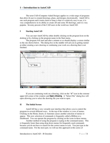
AutoCAD Selects Lines1 – Click here with mouse2 – Click here with mouse5. Hold down the CTRL key and press the C key. This will copy everything youhave selected to the program clipboard.6. Next, you switch from the detailed drawing to the assembly drawing you arecreating. You can do this by clicking on the big red “A” in the upper rightcorner and select the assembly drawing in the list of open files.7. Paste the view from the detailed drawing into the assembly drawing byholding down the CTRL key and pressing the V key. Use the mouse to movethe view to a convenient location then click to complete the copy.8. Repeat this process for all of the parts in the assembly. When you havefinished, you should have a drawing containing copies of all of the parts in theassembly. The figure below shows a bracket that is used to bolt two platestogether. We will use this as an example.Building the AssemblyAfter the parts have beencopied to the assembly drawing, wecan arrange them so that they areoriented correctly. We start byconnecting Parts 4 and 5. Use theMOVE command to move Part 4 sothat points “A” and “B” are at thesame location. Point “A” is located atthe intersection of the centerline andthe bottom of Part 4 and point “B” islocated at the intersection of thecenterline and the top of Part 5.Assembly Drawings in AutoCAD – R Greenlee214A3B5Page 3
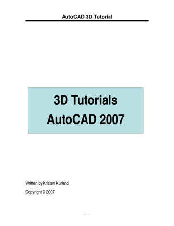
MOVESelect objects: wSpecify first corner:Specify opposite corner:Select objects:Specify base pointSpecify second point{Part 4 will be selected with a window}{Click above and to the left of Part 4}{Click below and t the right of Part 4}{Press enter – the selection is complete}{Click on Point “A” at the intersection of the holecenterline and the bottom of Part 4}{Click on Point “B” at the intersection of the holecenterline and the top of Part 5The resulting placement isshown in the figure on the right.CDNext we will align point “C”with point “D”. Point “C” is located atthe intersection of the centerline withthe right side of Part 1. Point D islocated at the intersection of thecenterline and the left side of Part 4 asshown in the figure on the right. Hereagain, use the MOVE command tomove Part 1 into the correct location.Assembly Drawings in AutoCAD – R GreenleePage 4
Next, create a copy of the boltand insert the copy into the verticalhole. The copy is created with theCOPY command as shown below.Copy bolt to hereCOPYSelect objects: WSpecify first corner:Specify opposite corner:Specify base point:Specify second point{select the bolt with a window}{click above and to the left of the bolt}{click below and to the right of the bolt}{select a point on the bolt}{select a point away from all other objects to placethe bolt}Specify second point or [Exit/Undo] Exit :{press enter}The results of the copy are shown in the figure above. The bolt on the rightwill be rotated 90 degrees clockwise and inserted into the hole. The first step is torotate the bolt which is done with the ROTATE command. This command alsorequires that you select all of the objects to be rotates and you can again use the Woption to create a selection window. When you rotate the bolt, be careful not to rotateit over another part. You can control the rotation by picking a base point (center ofrotation) that is near the end of the boltROTATESelect objects: WSpecify first corner:Specify opposite corner:Select objects:Specify base point:Specify rotation angle: -90{click above and to the left of the bolt}{click below and to the right of the bolt}{press enter}{click near the bottom to keep the bolt from rotatingover another part. In this case pick point 1}{the angle is negative because the rotation isclockwise}Now we insert the bolt into the vertical hole. Use the MOVE command andselect a mid point on the bolt head (point 1) and the intersection of the centerline andthe top of the hole (point 2) as the base point and the second point in the MOVEcommand.MOVESelect objects:WSpecify first corner:Specify opposite corner:Select objects:{upper left}{lower right}{press enter}Assembly Drawings in AutoCAD – R GreenleePage 5
Specify base point:Specify second point:mid{enter mid and select point 1}{let OSNAP find the intersection of the top of thehole and the centerline – point 2}12When you have finished, your drawing should resemble the one shown aboveon the right.Next copy the nut, rotate it -90degrees, and place it on the bolt as shown inthe figure at the right. You can use the COPY,ROTATE, and MOVE commands just as youdid for the bolt. The resulting drawing isshown on the right.Some of the interior lines of the bolt, should be changed to hidden lines. Youcan make these changes with the CHANGE command.CHANGE{Select the lines that should be changed to the hidden layer}Select objects: 1 foundSelect objects: 1 found, 2 totalSelect objects: 1 found, 3 totalSelect objects:Specify change point or[Properties] ]: PEnter property to change[Color/Elev/LAyer/LType/ : LAEnter new layer name Object :Enter property to change[Color/Elev/LAyer/LType/ :Assembly Drawings in AutoCAD – R Greenlee{press enter}{we are changing the properties}{we want to change the layer}hidden{press enter}Page 6
The bolt with hidden lines withcorrect hidden lines is shown on theright.These lineswere changedto HIDDENContinuing moving androtating parts until the parts are fullyassembled and your drawing looks likethe one on the right.Assembly Drawings in AutoCAD – R GreenleePage 7
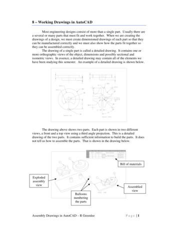
Creating BalloonsNext, we need to create theballoons that identify parts. Balloonsare called leaders in AutoCAD and wemust first define balloon style leadersbefore we can draw them. Start bytyping:Click on “New”mleaderstyleThis produces the dialog box on theright. Click on the “New” button tocreate a new leader style.31. Enter “Balloons” forthe name of the newleader style we arecreating.212. Mark the“Annotative” checkbox.3. Click on “Continue”.4Next we define how the newmultileader will look in the dialog boxshown on the right.121. Click on the “Content” tab2. Select “Block” for themultileader type33. Select “Circle” for the sourceblock4. Select the “Leader Structure”tabAssembly Drawings in AutoCAD – R GreenleePage 8
The settings in the “LeaderStructure” tab are:2141. Mark the “Maximum leader 3point” check box.52. Set the number to 273. Mark the “Second segmentangle” check box694. Set the angle to 05. Mark “Automatically include8landing”6. Mark “Set landing distance’7. Set the landing distance to 1.5 or what seems reasonable. This is a personalpreference.8. Mark “Annotative”9. Click “OK”In the “Multileader StyleManager” dialog box:21. Make sure “Balloons” ishighlighted.2. Click on “Set Current”3. Click on “Close”13Now you are ready to draw the leaders. Change the layer to “Dimension”layer and create the balloons by clicking on:1. Click on the “Annotate” tab at the top of the window2. Click on the “Multileader” icon in the annotate ribbon at the top of thewindow.3. Click at a point on a part whereyou want the leader to start4. Click where you want theballoon to be placed5. Enter the number of the part.124Repeat the process above untilall of the parts have been numbered.When you have finished, your drawingshould look like the one on the right.The numbers may appear a little smallbut they are annotative and will havean appropriate size on the drawingsheet.3354Assembly Drawings in AutoCAD – R GreenleePage 9
Placing on the SheetNext we will place the drawing on the sheet. We do this using the sametechnique we have used before. Click on:1.2.3.4.Click on the “Layout1” tab at the bottom of the window.Double click in the drawing area to activate the viewport.Enter the command zoom allUse the mouse to drag the drawing to the correct location. Size the drawingby scrolling the wheel on the mouse.5. If the arrowheads are too small, correct their size by modifying theMultileader style. Use the “Leader Format” tab to change the size of thearrowheads.The drawing should be locatedas shown in the figure on the right.The assembly is placed on the left sideof the drawing sheet to leave room forthe bill of materials.Bill of MaterialsNext we will create the bill of materials (BOM). The bill of materials is atable that lists:1.2.3.4.The part numberThe part nameThe number of parts required for the complete assemblyThe material from which the part is made. The material is not listed forpurchased parts such as bolts, nuts, etc.You can create the table with the TABLE command or you can just draw it. It isfrequently simpler to just draw it and that is what we are going to do. We will use theOFFSET command to create this table.Assembly Drawings in AutoCAD – R GreenleeP a g e 10
OFFSETSpecify offset distance: 10Select object to offset:Specify point on side to offsetor [Exit/Multiple/Undo] Exit : MSpecify point on side to idesidesidesidetotototototo{Distance between lines}{Click on the top border line}{Enter M to create multiple offsets usingthe 5mm offset distance}{Click below the top border line 6 timesuntil all of the lines have been created}offset:offset:offset:offset:offset:offset or [Exit/Undo]: {Press enter twice toexit}Next we create vertical lines byoffsetting the right border line. Createlines at 20, 35, 65, and 85 from theright border. After you have createdthe vertical lines, use the TRIMcommand to trim the lines to form atable. The results are shown on theright.1Next, use theMTEXT command to fillin the table. You mayneed to set the size of textused in the table. Do thisby clicking on:21. Click on the“Annotate” tab.2. Click on the “Text”arrow3. Check the“Annotative” box4. Set the text height to 55. Click on “Apply” then “Close”Assembly Drawings in AutoCAD – R Greenlee354P a g e 11
Finally, fill in the table as shown below.Assembly Drawings in AutoCAD – R GreenleeP a g e 12
6. Next, you switch from the detailed drawing to the assembly drawing you are creating. You can do this by clicking on the big red “A” in the upper right corner and select the assembly drawing in the list of open files. 7. Paste the view from the detailed drawing into the assembly drawing