Transcription
LECTURE 1INTRODUCTION TO MACHINEDRAWING1. Graphic LanguageA technical person can use the graphic language as powerful means of communicationwith others for conveying ideas on technical matters. However, for effective exchange ofideas with others, the engineer must have proficiency in (i) language, both written andoral, (ii) symbols associated with basic sciences and (iii) the graphic language.Engineering drawing is a suitable graphic language from which any trained person canvisualize the required object. As an engineering drawing displays the exact picture of anobject, it obviously conveys the same ideas to every trained eye.Irrespective of language barriers, the drawings can be effectively used in other countries,in addition to the country where they are prepared. Thus, the engineering drawing is theuniversal language of all engineers.2. Importance of Graphic LanguageThe graphic language had its existence when it became necessary to build new structuresand create new machines or the like, in addition to representing the existing ones. In theabsence of graphic language, the ideas on technical matters have to be conveyed byspeech or writing, both are unreliable and difficult to understand by the shop floor peoplefor manufacturing. This method involves not only lot of time and labor, but alsomanufacturing errors. Without engineering drawing, it would have been impossible toproduce objects such as aircrafts, automobiles, locomotives, etc., each requiringthousands of different components.3. Need for Correct DrawingsThe drawings prepared by any technical person must be clear, unmistakable in meaningand there should not be any scope for more than one interpretation, or else litigation mayarise. In a number of dealings with contracts, the drawing is an official document and thesuccess or failure of a structure depends on the clarity of details provided on the drawing.Thus, the drawings should not give any scope for misinterpretation even by accident.It would not have been possible to produce the machines/automobiles on a mass scalewhere a number of assemblies and sub-assemblies are involved, without clear, correctand accurate drawings. To achieve this, the technical person must gain a thoroughknowledge of both the principles and conventional practice of drawing. If these are notachieved and or practiced, the drawings prepared by one may convey different meaningto others, causing unnecessary delays and expenses in production shops.1
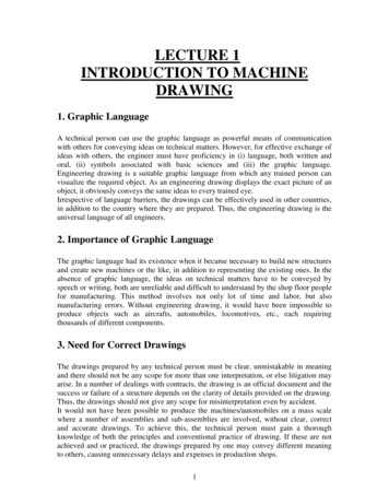
Hence, an engineer should posse good knowledge, not only in preparing a correctdrawing but also to read the drawing correctly.4. Classifications of Drawings4.1Machine DrawingIt is pertaining to machine parts or components. It is presented through a number oforthographic views, so that the size and shape of the component is fully understood. Partdrawings and assembly drawings belong to this classification. There are two types ofmachine drawing:4.1.1 Part DrawingComponent or part drawing is a detailed drawing of a component to facilitate itsmanufacture. All the principles of orthographic projection and the technique of graphicrepresentation must be followed to communicate the details in a part drawing. Fig. 1shows an example of part drawing ( Note that the drawing was drawn according to adifferent drawing standard)Fig. 1 Part drawing of a machine component.2
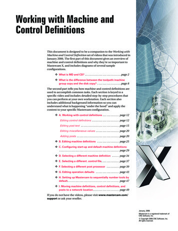
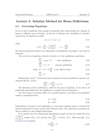
Fig. 2. Part drawing Examples.4.1.2 Assembly DrawingA drawing that shows the various parts of a machine in their correct working locations isan assembly drawing. Fig. 3 shows an example of an assembly drawing ( Note that thedrawing was drawn according to a different drawing standard).3
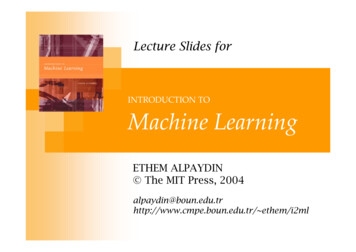
Fig. 3. Assembly drawing of a machine.The assembly drawing can be shown in exploded view as shown in the Fig. 4.Fig. 4. Exploded view drawing of a machine.4
4.1.3 Production DrawingA production drawing, also referred to as working drawing, should furnish all thedimensions, limits and special finishing processes such as heat treatment, honing,lapping, surface finish, etc., to guide the craftsman on the shop floor in producing thecomponent. The title should also mention the material used for the product, number ofparts required for the assembled unit, etc. Fig. 5 shows an example of a productiondrawing ( Note that the drawing was drawn according to a different drawing standard)Fig. 5. Production drawing of a machine component5
An assembly drawing of a fuel injector for a diesel engine. Drawn to BS and ISO Standards, as shown in Fig. 6, this is a typicalprofessional CAD drawing which could be produced using most CAD software on the market.Fig. 6. Part drawing of a machine component.6
5. Drawing Layout5.1 Drawing LayoutFig. 7. Drawing Layout.7
5.2 Drawing Layout ExampleFig. 8. Drawing Layout Example.8
5.3 Drawing Layout example solutionFig. 9. Drawing Layout Example Solution.9
5.4 Table dimensionsFig. 10. Drawing Table.10
5.5 An example of filled tableFig. 11. Filled-Drawing Table.11
6. Drawing Conventions6.1. Line Types12
Fig. 12. Example of different line types.Interrupted view applicationFig. 13. Interrupted view example.13
6.2 Part numberingFig. 14. Part Numbering Example.6.3 Drawing conventions14
6.4 Abbreviations for MaterialsMaterialAluminumBronzeCast IronStainless SteelAbbreviationALBRZC.I.ST.7. Lettering15
8. Hatching ReviewFig. 15. Hatching of two adjacent parts.8.1 Sections not to be hatchedFig. 16. Example of sections.16
Indicate the correct and incorrect methods of sectioning of machine elements representedin Fig. 14.Fig. 17. Hatching of two adjacent parts.Indicate the correct and incorrect methods of sectioning of machine elements representedin Fig. 15.Fig. 18. Hatching of two adjacent parts.Indicate the correct and incorrect methods of sectioning of machine elements representedin Fig. 19.17
Fig. 19. Hatching of two adjacent parts.18
9. Sectional ViewA sectional view is obtained by imagining the object, as if cut by a cutting plane and theportion between the observer and the section plane being removed. Figure 4.1a shows anobject, with the cutting plane passing through it and Fig., the two halves drawn apart,exposing the interior details.Fig. 20. Section Example.19
Indicate the correct and incorrect methods of sectioning of machine elements representedin Fig. 19.Fig. 21. Correct and incorrect section views.Half SectionFig. 22. Half Section Example.20
10. First and Third Angel ProjectionFirst AngleThird AngleFirst AngleThird AngleFig. 23. First and Third Angel Projection.21
KNUCKLE JOINTKnuckle joint is a type of mechanical joint used in structures, to connect two intersectingcylindrical rods, whose axes lie on the same plane. It permits some angular movementbetween the cylindrical rods (in their plane). It is specially designed to withstand tensileloads.Fig. 24. Knuckle Joint Examples.22
Applications of Knuckle JointTractorsTrainsAutomobile wipersCranesRobotic jointsAdvantages of Knuckle Joint:Knuckle joint can withstand large tensile loads.It has good mechanical rigidity.It is easy to manufacture and set up.It can be easily dismantled and assembled.Design is simple and easy.Disadvantages of Knuckle Joint:The joint cannot withstand large compressive loads.It permits angular movement in only one plane.Fig. 25. Assembly of Knuckle Joint.23
Split PinFig. 26. Split Pin.24
Component or part drawing is a detailed drawing of a component to facilitate its manufacture. All the principles of orthographic projection and the technique of graphic representation must be followed to communicate the details in a part drawing. Fig. 1 shows an example of part drawing ( Note t


![Academy Cloud Foundations Course Outline [English]](/img/13/academy-20cloud-20foundations-20course-20outline-20-english.jpg)