Transcription
Engineering Drawings:Detail DrawingsA short lecture on Detail Drawings as per the Australian Standard AS1100By Paul Briozzo
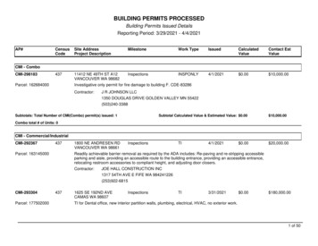
What is a Detail Drawing ?An Engineering Detail Drawing contains the key points to enable the manufacture ordescription of a single component that defines and communicates part of a completedesign to other interested parties.
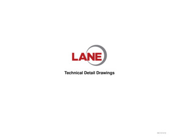
Detail Drawing: An Example
Detail Drawings must provide sufficient information to enable themanufacture a part. Enough orthogonal views : enough views to adequate describe the component.Dimensions : Must be evenly distributed, structured and not duplicated.Scale : Drawing must state the scale used to fit the component onto the drawing sheet.The type of projection : Third Angle Projection is mandatory in ENGG1960.Drafting Standard (AS1100) : This is effectively covered in prescribed texts.The name or title of drawing : What is the name of the component ?The drawing number : What is the number (in-house system) of the component ?Dimensional units used : mm, m, inches, feet etc.Tolerances : What are the manufacturing tolerances for each part of the component.Surface texture (or roughness) : How smooth/rough each part of the component has to be.Treatments (coatings, tempers etc.) : Does the component need protective coatings ?Reference to assembly drawing : What does my component fit into ?Material : What material is the component manufactured from ?Drafter (who drew it), Checker (who checked it), Approver (who approved it) and datesZones : Where on the drawing are you referring to ?Revision : What has been revised and why and what revision is this drawing ?Sheet Size : A4, A3, A2, A1 or A0Company : School of AMME, University of SydneySheets Reference (eg. Sheet 1 of 3) : When more than one sheet is required.
Enough Orthogonal ViewsWall Bracket drawing shows three regular views. Could have been donewith two regular views and a sectional view replacing the end elevation.
DimensionsWall Bracket drawing shows dimensioning reasonably well located with theexception of the plan view which has three dimensions located within theview.
ScaleWall Bracket drawing shows the scale to which the drawing is drawn within thetitle block as is required by AS1100. The scale in this case is 1:1 or “Full Size”other preferred scales in the metric system are:For enlargement: 2:1, 5:1, 10:1, 20:1, 50:1For reduction:1:2 (half size), 1:2.5, 1:5, 1:10, 1:20, 1:50,1:100, 1:200, 1:5001:1000, 1:2000, 1:5000, 1:10 000
The Type of Projectionrd(3 Angle)Wall Bracket drawing shows the Third Angle Projection Symbol within the title block.The symbol is sometimes located outside of the title block. The conical cylinderrepresents the orientation of views that should be reflected in your drawings.
Drafting Standard AS 1100The Wall Bracket drawing shows the Drafting Standard used within the title block.AS1100 is the drawing standard that is used within Australia. It defines every aspectof the drawing. AS1100 provides a standard that (if followed by all companies), allowsfor a clarity, understanding and uniformity across all drawings generated nation wide.
Name or Title of Drawing /Drawing NumberThe drawing shows its name, WALL BRACKET within the title block. The name ortitle of the drawing is the name by which (in this case) the detail drawing iscommonly referred to by many parties involved. This name is not unique.The drawing number (abbreviated to DRG No) is the part number which is oftenused to locate or recognise the part within a database. This number is unique.There may be many parts that are named “WALL BRACKET”. However, thenumber of the drawing must be unique.
Dimensional Units UsedThe units used throughout the drawing. In this case millimetres are used. Howeverother metric or imperial units may be used. E.g. microns, metres, inches or feet.Centimeters are not used in Engineering Drawings.
TolerancesTolerance can be defined as the difference between the maximum and minimumlimits of size. In this view, two tolerances are shown. One tolerance can be seenfrom the back of the Wall Bracket to the centre of the hole. The black triangle on theend of the dimension line infers that this is a datum surface. The other tolerancerefers to the hole diameter.
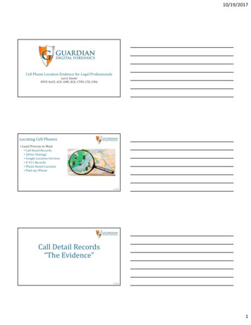
Surface Texture or RoughnessSymbols which indicate the surface texture of roughness that a component or aparticular feature of a component requires must be inserted.The surface texture symbol should be located sothat it can be read from the bottom orright hand side of the drawing.
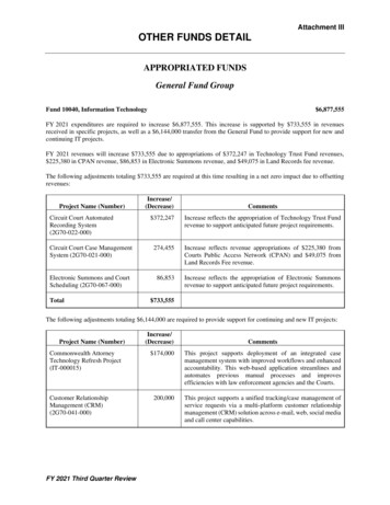
Standard Roughness Values
Surface Treatments (coatings, tempers etc.)The treatment or coating that the component is finished to is stated in the titleblock. If the process is a company or military standard that is often followed e.g.the aircraft industry, NASA, The Australian Army, then reference to a standarddata sheet is made.
Reference to Assembly DrawingsDetail drawings seldom describe the intent of an engineering design. An engineeringdesign is usually defined by many individual detail drawings which combine to forman assembly drawing. The name and or drawing number of the assembly drawing inwhich the detail drawing is “called up” or “used on” is stated in the title block.
MaterialEngineering designs are highly dependant on the material from which they aremanufactured. Clearly this is something that must be stated in the drawing as itvital information that must be passed on to the manufacturer of the part and manyother parties. This information is normally stated in the title block. If theinformation is extensive a separate note located in the drawing or a separate datasheet may be used.
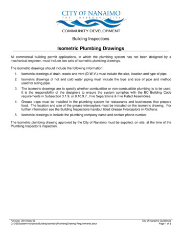
Names and DatesEngineering designs are the work of many people within an organisation. Theinitials or names indicate who was responsible for the various duties. In the abovetitle block, DRN indicate who was responsible for drafting the drawing. The initialsCKD indicate who checked the drawing. Usually this task is completed by a highlyexperienced drafter or the chief drafter in a drawing office. The initials APPDindicate who approved the drawing. This signatory is usually the project engineerwho overseas the entire project. The title “ISSUED” is the final approval whichwould be signed off by a senior or chief engineer.These signatures carry responsibilities and dictate accountability.
Zone Reference SystemThe numbers and capital letters surrounding a drawing provide a method whereby two peoplemay discuss (perhaps over a telephone call) a particular feature on a drawing. This is mostuseful on large format sheets such as A0 and A1 sizes.
Revisions or ModificationsRevisions to designs may occur due to design development, manufacturing processrefinement or the removal of errors. These changes require revisions to all of thedrawings affected. In the drawing above, a revision is noted regarding the change ofthread from 5/8” Whitworth to M16 Metric. There is usually more documentationassociated with these changes than is noted in this example.
Drawing Sheet SizesFrom AS1100 Part 101, the preferred paper sizes are A0, A1, A2, A3 and A4. An A0sheet has 1m2 of drawing area available. Subsequent sheet sizes are simply halfvalues of their predecessor. In this subject, A4 and A3 are the two sizes that we will bedealing with as these are two sizes that we have printing facilities for.
Name of Company orOrganisationIn the example above, the Company that owns the rights to the drawing is “A.Shambles Ltd.” In your work within this subject, the organisation should be noted as“The School of AMME, University of Sydney – ENGG1960”
Drawing Sheet ReferenceMany detail designs require multiple sheets to adequately define their content.Multiple views, auxiliary views, sections, extensive title blocks and notes may requiremore space than is available on a single sheet. If this is the case, then multiple sheetsmay be used. In the example above please note that this is, “SHEET 1 of 1” i.e. onlyone sheet is required to adequately define the detail design on a single sheet of A2 .A multiple sheet drawing (or assembly) must have all drawing sheets quoting thesame drawing number and name.A multiple sheet drawing (or assembly) must be referenced sequentially i.e. SHEET 1of 3, SHEET 2 of 3, SHEET 3 of 3 etc.
Drawing Sheet Reference(a bad example)Why ?
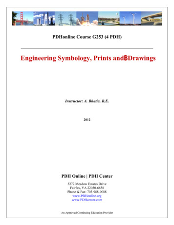
Detail Drawing Example
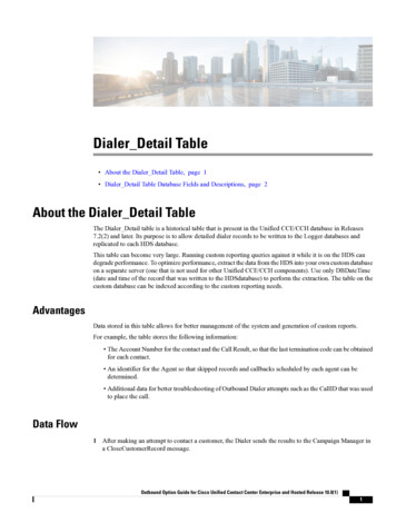
Detail Drawing Example:Lotus Elan Recreation
Name or Title of Drawing / Drawing Number . The drawing shows its name, WALL BRACKET within the title block. The name or title of the drawing is the name by which (in this case) the detail drawing is commonly referred to by many parties involved. This name is not unique. The drawing number (abbreviated to DRG N. o) is the part number which is oftenFile Size: 2MBPage Count: 28