Transcription
62TE UpdateFront Wheel Drive 6 SpeedPresented by:Mike SouzaATRA Senior ResearchTechnician
Welcome To Today’sPresentationSponsored By:62TE Update Webinar 2014 ATRA. All Rights Reserved.
Why Six-Speed?The 62TE transaxle offers distinct advantages over four-speedtransaxles. Providing additional ratios offers quicker acceleration due toshorter shift intervals and the ability to maintain an engine’s optimal RPMrange, providing the highest efficiency. This translates into increased fueleconomy.
The 62TE is the new generation of FWD/AWD Transaxles inproduction for Dodge/Chrysler. The concept has been aroundfor many years but has been introduced in the 2007 Model Year. These models include: “JS” Seabring, Seabring Convertible,and Avenger with the 3.5L V6 “CS” Pacifica with the 4.0L V6. The concept was to take a proven reliable 41TE (4 speed) andsplit the transfer/pinion drive with an underdrive/direct clutch todrive a double ratio to the final drive. Although this is classified as a 6 speed fwd transaxle, there are7 forward speeds due to the addition of a 4th gear prime ratiothat is used during a 6-4 kickdown. This prevents a double swap of components allowing for asmooth kickdown.
The 62TE transaxle is identified by a bar code label (1) that isfixed to the transaxle or the “PK” number plier CodeComponent CodeBuild Day (Julian Date)Build YearLine/Shift CodeBuild SequenceLast Three Part Number DigitsRevision LevelTransmission Part NumberPart Number Prefix
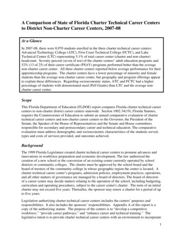
62TE Three Speed SensorsISSThe ISS has been relocated to the top of the case, and like the 41TE, continuesto read turbine speed from the input clutch hub.TSSThe 40/41TE OSS has been relocated to the rear of the case (backside) andrenamed the TSS. It continues to read rotation of the front annulus/rear carrierassembly.OSSThe OSS is located at the rear of the case and is unique to the 62TE. It readsthe rotation of the underdrive compounder output carrier.Input ShaftSpeed Sensor (ISS)Transfer ShaftSpeed Sensor (TSS)Crank SensorOutput ShaftSpeed Sensor (OSS)
62TE Case ConnectorThe are two different metals used to control andsignal the module both solenoid command andcircuit monitors. Pressure Switches are GOLD pinsand Solenoids are TIN pins
62TE Pressure Switch Status
Other Changes from the 41TE to the 62TE RFE-style solenoid/pressure switchassembly with 23-way connector Electronically Modulated ConverterClutch (EMCC) Variable Force Solenoid (VFS) Line Pressure (LP) VFS Line Pressure sensorRFE Style Transaxle Range Sensor (TRS)Solenoid PressureTCC solenoid(EMCC) VFSLine Pressure(LP) VFSSwitch AssemblyLine PressureSensor (Transducer)Transaxle Range Sensor (TRS)
Other Changes from the 41TE to the 62TE Low clutch switch valve New blocker valve (Direct Clutch Switch)Prevents simultaneous application of the DC and LCTCC Switch ValveLow Clutch Switch ValveTCC Control ValveSolenoid Switch Valve#2#1Blocker Valve(Direct Clutch Switch)TCC Regulator ValveL/R Switch ValveManual ValvePressure Regulator Valve
Other Changes from the 41TE to the 62TEThe 62TE valve body has nine (9) check balls (used for plugs)and four used in the hydraulic shift control circuit:The 9 check balls used for plugsare non removable.Some valve bodies do nothave the U/D check ball #2.
Other Changes from the 41TE to the 62TE Three additional oil transfer tubes which supply the UD compounderassembly
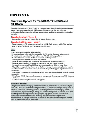
This 6 speed transaxle is basically a 41TE with some additionalcomponents referred to as the Underdrive (UD) Compounder Assembly.Underdrive (UD)Compounder Assembly: 41TELow Clutch (LC)Direct Clutch (DC)Overrunning Clutch (ORC)Planetary gear set62TE
The underdrive compounder assembly has two modes ofoperation: Direct and Reduction.The 2-3, 3-2, and 4-2 shifts require a “Double Swap” shift. Thisoccurs when two elements are turned off while two differentelements are engaged.The clutch-to-clutch synchronization takes place within 40 – 70milliseconds, producing a smooth shift. If the underdrivecompounder assembly shifts too early (in relation to the shiftstaking place in the main centerline), a shudder or harsh shiftresults.If the underdrive assembly shifts to late, the driver experiences a“Double Bump” sensation.To avoid a double swap shift in a 6-4 downshift, the transaxle shiftsinto 4th prime, which requires the deactivation of the OD clutch andthe simultaneous application of the UD clutch.
A freewheel (sprag) is used to provide this nonsynchronousclutch apply and release sequence.The sprag holds in first, third and fourth providing a smoother 12, 2-1, 4-5 and 5-4 shift.P A AppliedSame Ratios carried over from the 41TE H Holding * Limp-in Mode Applied in coast onlyP Prime
Power Flow
Power Flow
Power Flow
Power Flow
Power Flow
Power Flow
Power Flow
Power Flow
Compounder Assembly RemovalRemove the valve body & feed tubesbefore removing compounder assemblyRemove snap ring(no need to remove all the bolts)
Compounder Assembly RemovalThe O.E. tool or similar makes removal of the Compounder Assembly amuch easier job.Only remove bolts neededto install toolMiller Tool #9908
Main Compounder ComponentsPlanetary AssemblyDirect ClutchLow ClutchOver-run Clutch Assembly (Sprag)
Component DisassemblyRemove the Planetary Gear set.There is an Adjustable Shimbetween the Sun Gear & Planet.
Component DisassemblyUsing two small picks or scribes remove the Retainer Clip3Tabs
Component DisassemblyUsing two small picksor scribes remove theSplit BearingThen Remove theDirect Clutch assembly.Check the “Split” Roller Bearingfor wear or damage
Direct Clutch Disassembly – Reassembly1: Remove Tapered Snap ring2: Remove Selectable Plate3: Remove #1 thrust bearing, hub, and #2 thrust bearing4: Remove single sided frictions5: Compress Balance piston with tool #8250 and removesnap ring6: Remove PistonASSEMBLE (Reverse Procedure)Miller # 9727 pistoninstallation tool
Direct Clutch EndplayMeasure with clutch hub removedMeasure clutch clearance using30 psi of air pressure throughcompounder feed hole.Clearance is 0.037” to 0.056”
Low Clutch Disassembly – Reassembly1: Remove Transfer Shaft2: Remove Sprag, Snap Ring, Reaction Plate andClutch Plates3: Remove Clutches and Steels4: Compress Return spring with tool #97255: Remove PistonASSEMBLE (Reverse Procedure)Miller Tool 9725
Low Clutch EndplayMeasure clutch clearance using 30 psi of air pressure throughcompounder feed hole.Clearance is:0.048-0.76mm (.018-.029 in)
Underdrive “One-Way Clutch”The inner race has offset splines, the outer race has the ID groove(faces down when installed correctly). The outer race should rotatecounter clockwise when all is together correctly.HeldTurnID Groove
Scarf Cut Sealing RingsCheck the Scarf Cut Sealing Rings for wear anddamage. Replace as needed.
Common ProblemDirect Clutch Piston De-lamination (split rubber seal).Some pistons with minimal damage may air check well.
Torque ConverterThe 62TE Torque Converter is what they call as “Squished Design”.This change had to happen do to space availability.41TE62TE
Torque Converter
62TE Front PumpThe 62TE Front Pump is also called “squished design” do to thelimited space. Side by side the changes are obvious.41TE62TE
62TE Front Pump AssemblyWhen assembling the front pump it is important to note that the pumpgears now have assemble dots. These dots must face up whenassembling.41TEThe side of the gears with thegreater chamfer on the end ofthe teeth goes into the pumppocket first (facing down).62TE
62TE Front Pump AssemblyFace to gear clearance is 0.0008 – 0.0018 in. Check with plasticgauge!Outer gear and pocket0.0079 – 0.0035 in.Outer gear and crescent0.0023 – 0.0035 in.Inner gear and crescent0.0036 – 0.0151 in.
Cooler Bypass ValveThe cooler bypass valve is a high risk area. It is a good idea to replace thevalve with a NEW VALVE when doing a repair on the transmission.
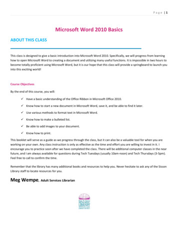
Most Common FailureLow Clutch Sealing Ring GroovesSealing RingGrooves
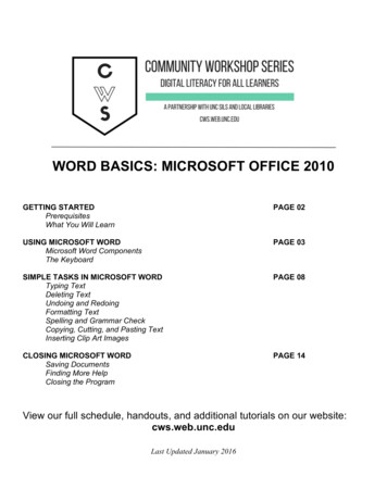
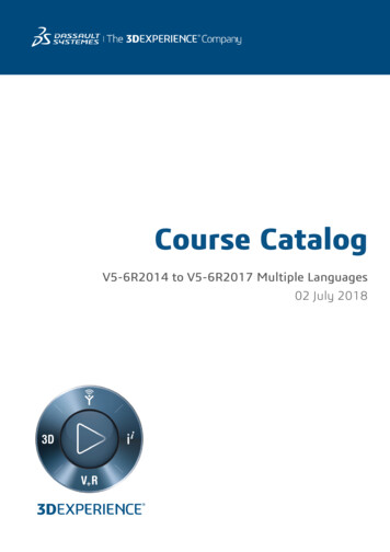
NormalMost common failureRing Land WearUnderdriveCompounderLow Clutch DrumApprox. 0.005”Clearance
Badly WornMost common failureRing Land WearUnderdriveCompounderLow Clutch Drum
Extreme WearMost common failureRing Land WearUnderdriveCompounderLow Clutch Drum100% FailureRateAvailable inaftermarket with steelinsert
New Failure On The Technical HotlineUnderdrive CompounderDirect Clutch HousingA common problem isthe snap ring groove iswornDTC’s P0792, P0735, No Line Rise, Slips 1-2
Most Common Code DTC P2764, TCC Stuck“ON”Line Pressure TransducerReplace theTCC solenoidPart #5169313AA.Solenoid BlockLine Pressure Solenoid
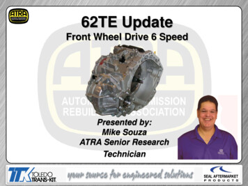
Most Common Builder ErrorIf the seal is installed upside down it will block the 2/4 clutch circuit andresult in a loss of 3rd in limp mode, 4th or 6th. Install the seal with the slotfacing up as shown.Correct“First TimeBuilder Error”
Today’s PresentationSponsored By:Thank You For Attending62TE Update Webinar 2014 ATRA. All Rights Reserved.
To avoid a double swap shift in a 6-4 downshift, the transaxle shifts into 4th prime, which requires the deactivation of the OD clutch and . is used to provide this nonsynchronous clutch apply and release sequence. The sprag holds in first, third and fourth providing a smoother 1-2, 2-1, 4-5 and 5-