Transcription
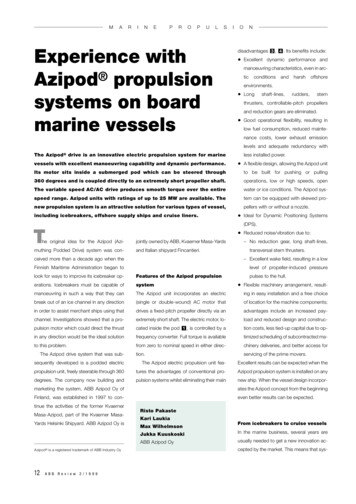
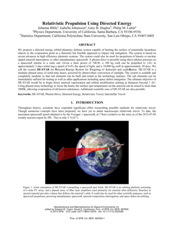
Relativistic Propulsion Using Directed EnergyJohanna Biblea, Isabella Johanssona, Gary B. Hughesb, Philip M. LubinaaPhysics Department, University of California, Santa Barbara, CA 93106-9530;bStatistics Department, California Polytechnic State University, San Luis Obispo, CA 93407-0405ABSTRACTWe propose a directed energy orbital planetary defense system capable of heating the surface of potentially hazardousobjects to the evaporation point as a futuristic but feasible approach to impact risk mitigation. The system is based onrecent advances in high efficiency photonic systems. The system could also be used for propulsion of kinetic or nucleartipped asteroid interceptors or other interplanetary spacecraft. A photon drive is possible using direct photon pressure ona spacecraft similar to a solar sail. Given a laser power of 70GW, a 100 kg craft can be propelled to 1AU inapproximately 3 days achieving a speed of 0.4% the speed of light, and a 10,000 kg craft in approximately 30 days. Wecall the system DE-STAR for Directed Energy System for Targeting of Asteroids and exploRation. DE-STAR is amodular phased array of solid-state lasers, powered by photovoltaic conversion of sunlight. The system is scalable andcompletely modular so that sub elements can be built and tested as the technology matures. The sub elements can beimmediately utilized for testing as well as other applications including space debris mitigation. The ultimate objective ofDE-STAR would be to begin direct asteroid vaporization and orbital modification starting at distances beyond 1 AU.Using phased array technology to focus the beam, the surface spot temperature on the asteroid can be raised to more than3000K, allowing evaporation of all known substances. Additional scientific uses of DE-STAR are also possible.Keywords: DE-STAR, Photon Drive, Directed Energy, Relativistic Travel, Interstellar Travel1. INTRODUCTIONThroughout history, scientists have expended significant effort researching possible methods for relativistic travel.Though numerous concepts have been proposed, we have yet to attain macroscopic relativistic travel. To date, themaximum spacecraft speed obtained is by the Voyager 1 spacecraft, at 17km/s (relative to the sun), as of the 2013-07-05weekly mission report by JPL. This is only 5.7x10⁻⁵c.Figure 1. Artist conception of DE-STAR 4 propelling a spacecraft past Earth. DE-STAR is an orbiting platform consistingof a solar PV array, and a phased array of fiber laser amplifiers used primarily for asteroid orbit deflection. Reaction toejected material provides a thrust that deflects the asteroid’s orbit. It could also be used for other scientific purposes, such asspacecraft propulsion, powering interplanetary spacecraft, asteroid composition interrogation, and space debris de-orbiting.Nanophotonics and Macrophotonics for Space Environments VII,edited by Edward W. Taylor, David A. Cardimona, Proc. of SPIE Vol. 8876, 887605 2013 SPIE · CCC code: 0277-786X/13/ 18 · doi: 10.1117/12.2035346Proc. of SPIE Vol. 8876 887605-1
1.1 History of Relativistic Propulsion ResearchOne of the earliest projects focused on relativistic travel was Project Orion1, studied in the early 1950s at Los AlamosNational Laboratory. This proposed spacecraft used nuclear pulse propulsion, that is atomic bombs exploding behind thespacecraft, as their propulsion source. The resultant vehicle velocity expectation was between 0.08c and 0.1c. Concernregarding potential radioactive contamination resulted in the cancellation of the project. In 1973, the BritishInterplanetary Society initiated design of an unmanned interstellar spacecraft known as Project Daedalus2. The project,utilizing then current technology, proposed traveling 6 light years in approximately 50 years. Daedalus was a two-stagespacecraft design that employed fusion rockets. The first rocket stage obtained a projected speed of 0.071c over twoyears, and the second stage, spanning 1.8 years, achieved a cruising speed of 0.12c. The proposed Daedalus payload of450 tons made it ideal for scientific research. The Daedalus project concluded that Interstellar flight is achievable.Between 1987 and 1988, the US Naval Academy and NASA developed Project Longshot3, a spacecraft utilizing nuclearpulse propulsion powered by nuclear fission. Project Longshot proposed a prospective trip to Alpha Centauri B at0.045c, spanning 100 years. Other more exotic propulsion systems include antimatter propulsion such as the systemproposed by Robert Forward of Hughes Research Laboratories4. Antimatter annihilation emits pions whose kineticenergy is then converted into thrust. The Marshall Space Flight Center has built antimatter traps5 (HiPAT), necessary forthis engine, which store antiprotons for later use. Other areas of current thought that hold academic interest includegravity manipulation and warping of space-time.1.2 History of Photon PropulsionThe method of using a laser to propel spacecraft is not new, one proposed method would be to use a terrestrial laser6,while another method proposed by Robert L. Forward7 in 1984 suggests using a solar pumped laser. Forward proposesusing a 1000km diameter Fresnel zone lens to focus the laser beam on the spacecraft composed of a mirror systemweighing 1000kg. Further discussion by Young K. Bae8 describes the advantages of using a Photonic Laser Thruster(PLT) as opposed to more conventional engines to build an Interstellar Photonic Railway. This futuristic railway wouldcompose of multiple manned space structures located along the "tracks" and used to propel spacecraft onward.2. METHODOLOGY2.1 DE-STARWhile there have been many suggested methods of interstellar travel, the method we propose, in particular does notrequire on-board engines. Utilization of the DE-STAR 4, a conceptual space-based laser system9, as a photon drive,propels a 100kg spacecraft with a 30m diameter reflector to 0.6% the speed of light at the edge of the solar system. If weassume full reflector illumination at the edge of the solar system (roughly 900m diameter reflector) then we obtain 2% c,which is increased to 3% (21/2 times 2% c, see Section 2.3) with continued partial illumination for large distances. DESTAR is a proposed modular system composed of an array of phase-locked lasers and powered by solar panels. Withcurrent technology, a DE-STAR 4 (104m per side) outputs an average of 70GW laser power. A reflector mounted at therear of the spacecraft reflects incoming photons generating 470N thrust. In this paper, we demonstrate how directedenergy from a DE-STAR could be used as a mechanism for relativistic propulsion, as depicted in Fig. 1.2.2 Case I: Spot Size Smaller Than Reflector (Ds D)As the spacecraft travels away from DE-STAR the spot size of the lasers will grow and eventually be larger than thereflector on the spacecraft. While the spot size is smaller than the reflector, it is straightforward to solve for time as afunction of velocity. We know that the force due to the radiation pressure of the reflected laser beam isF where P is the power at the spacecraft, andεr 1 εPε rcwhere(1)εis the reflection coefficient,ε 0for no reflection(absorption) and ε 1 for complete reflection. We note that given an initial power, P0, from DE-STAR, relativisticeffects must be taken into account. That is:Proc. of SPIE Vol. 8876 887605-2
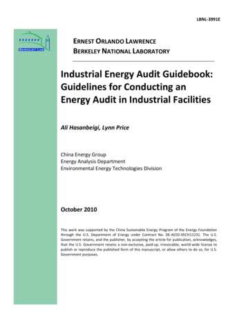
F P0ε rγcSince it is known that force is the derivative of the momentum,(2)ρ m0γ v , where m0 is the resting mass.P0ε r d ρ γcdt(3)P0ε r dγ dvv γ m0 γc dv dt(4)Further simplifying, we obtain t in terms of the relativistic speedβ v/cm0 c 2dβt P0ε r (1 β 2 ) 2(5)Which then solves to the analytical formm0 c 22 P0ε r β1 1 β ln 22 1 β 1 β(6)m0 c 2t 2 P0ε r β tanh 1 ( β ) 2 1 β (7)t We now can now invert our equation and obtain plots ofβversus time.We plot the speed achieved by a 100kg spacecraft during various time intervals after initial propulsion by DE-STAR 4 inFig. 2. The velocity is non-relativistic at early times followed by the transition to relativistic travel and ultimatelyreaching the relativistic limit.Figure 2. The left plot shows velocity versus time up to 10% c using the inverted equation for time (7), setting m0 100kg, P0 50GW, and ε r 2 , and depicts the spacecraft traveling at non-relativistic velocities for the first 46 days. As the velocity increases,the spacecraft begins to display relativistic effects. At approximately 4 years, the velocity approaches its relativistic limit, c, shown inthe right plot. This figure assumes a reflector size of sufficient diameter such that the spot size is always smaller than the reflector. Atsufficiently large time, this becomes unrealistic for all known materials. These figures confirm that our equations obey the relativisticlimit. For example, a time of 4.5x10⁶s corresponds to a spot size (diameter) of 7.2x10³meters and a time of 108s corresponds to a spotdiameter of 2.7x10⁶m.Proc. of SPIE Vol. 8876 887605-3
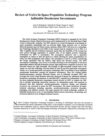
As a reality check, let us calculate how thick a reflector with diameter of 106m and mass of 100kg (as assumed in Fig. 2)must be. Given a density of 1g/cm3 we have a thickness of 10-13m, or 10-4nm. While this is not possible with currenttechnology (Section 2.4) it may one day be possible with nano-technology, we discuss this further in Section 2.4.We can confirm the non-relativistic limit forlnβ 1 1 β2 β 2 n 1 2β , β 11 β1 2n 1t m0 c 2m vc ρ(β β ) 0 P0ε r F2 P0ε r(8)(9)As expected, for heavy spacecraft (large m0) the time to relativistic speed is longer. In the instance of a 104kg spacecraftthe speed remains non-relativistic even after 190 months, as shown in Fig. 3.Figure 3. Plot of velocity versus time for m0 102kg (blue dashed line) and m0 104kg (red solid line) with P0 50GW andε r 2 . As expected the heavier mass is non-relativistic for a longer period of time. Be sure to note that 108s corresponds toan approximately 106m diameter spot size, an unrealistic sized reflector.A 1,000 kg (assuming a 30m reflector) spacecraft propelled by DE-STAR 4 (70GW) reaches Mars in about 10 days. The100 kg spacecraft discussed here reaches Mars in approximately 3 days. With constant illumination, the spacecraftundergoes rapid and prolonged acceleration followed by slow leveling off to constant velocity approaching therelativistic limit at approximately 5 light years distance from the Earth.Proc. of SPIE Vol. 8876 887605-4
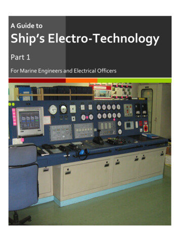
Figure 4. (a) Numerically solving for velocity and plotting it as a function of distance gives a sense of distance over whichthe spacecraft approaches it's relativistic limit. (b) Numerical solutions show rapid acceleration over the first six yearsfollowed by leveling off. Note that at the start, the acceleration is not much more than one third of Earth's gravity. (c) Inroughly 6 years the spacecraft will travel approximately 300,000AU ( 5ly). All of these plots assume Case I, where thereflector is always larger than the spot size. Both plots use m0 100kg, P0 50GW, and ε r 2 .While it is not straightforward to analytically solve for v(t), it is alternatively possible to use numeric methods to solvefor distance and acceleration. We numerically solved for d(t), a(t), and v(d), shown in Fig. 4.Figure 5. Plot of velocity, distance, and DE-STAR spot size (reflector size required) with respect to time. It is important tonotice the size of the reflector that would be required in Fig. 2 in order to obtain 90% the speed of light. The y-axiscorresponds to different units depending on which set of data you observe.We must take into consideration the size of the reflector necessary at large distances. Assuming DE-STAR 4 isdiffraction limited as seen in Fig. 5, we conclude that the reflector size required to reach 90% c (Fig. 3) is approximately106m. As this is unrealistic, we must consider what happens when the spot size is larger than the reflector.2.3 Case II: Spot Size Larger Than Reflector (Ds D)We consider the situation of a reflector size smaller than the laser spot size, that is Ds D as shown in Fig. 6. In thefollowing we assume perfect reflection, that is ε r 2 . Results are currently available for the non-relativistic case. Therelativistic case must be considered and is ongoing research.Proc. of SPIE Vol. 8876 887605-5
Figure 6. As the spacecraft distance from DE-STAR increases the laser spot size begins to spill over the area of the reflectorresulting in loss of potential power input.Figure 7. Diagram depicting relevant variables as discussed in Section 2.3. Note that image is not to scale.In order to solve the non-relativistic case we must first define L0 to be the distance at which Ds D. Now let L be thedistance to the reflector in meters. We solve for the kinetic energy from L 0 L0 (Ds D) (See Fig. 7.)KE1 FL0Given that L0 (10)PdDand F 0 we rewrite our kinetic energy to a more reasonable formc2λKE1 P0 dDcλ(12)We can further solve for the kinetic energy from L L0 , KE2 FdLL0(13)for Ds D we know that the force is given by2P L F 0 0 c L 2Proc. of SPIE Vol. 8876 887605-6(14)
By using equations (13) and (14) we can then solve for our kinetic energyKE2 P0 d 2 D 2 1 1 2cλ L0 L (15)We now want to find the total kinetic energy by adding (15) and (12).KEtotal 2 P0 L L0 2 cλ L0 (16)v( L) 4 P0 L L0 2 0 mc L (17)which we can then solve for v(L)As this calculation does not take into account relativistic effects it will only be accurate for v c. If we say that v0 is thespeed for which L L0, that is v0 4P0L0 , then for any subsequent distance we can writemcv( L) v0 2 L0L(18)This is especially important, as we learn that approaching infinite distance our speed will essentially be2v0 . Another 1/2point of interest is that the velocity is a function of m, so for small mass the velocity will increase. Mass isproportional to one over the square of the diameter, hence speed will be proportional to 1/D1/2. Though it iscounterintuitive, smaller reflectors (where the mass of the payload is insignificant compared to the reflector mass) gofaster. Since v (2aL)1/2 where a is the acceleration and is inversely proportional to mass ( 1/D2 ) and L is the distanceover which the acceleration occurs, which is proportional to D, the product is proportional to D-1/2. This raises thepossibility of highly relativistic speeds for small reflectors and nano-spacecraft. The key technological advance would bea small reflector capable of handling extremely large fluxes.2.4 ReflectorWe have alluded to the importance of the reflector, which is arguably the most critical component. The extreme amountof power (70GW) contacting the surface requires near perfect reflection. Since our laser is extremely narrow-band, wecan easily tune the reflector for lower energy loss. With dielectric coatings, 99.999% reflectivity efficiency has beenachieved on glass, and with current technology, it appears to be possible to achieve 99.99 % on plastics. Problems beginto arise as the reflectivity decreases. Excess energy heats up the reflector, potentially damaging or destroying it. Table 1depicts the temperature rise of a reflector of given reflectivity assuming 70GW power and only back-side emission,which lowers the temperature. Dual side emission would be better but is not assumed here to be conservative.Table 1. Table depicts the temperature due to heat dissipation for three different reflectivities. It is assumed that there areonly single side (back) emissions. These temperature elevations are practical for possible reflector materials.ReflectivityHeat DissipationTemperature99.999%800W/m2350K (76.85 C)99.995%4kW/m2520K (246.85 C)99.99%8kW/m2610K (336.85 C)A thin film roll coat reflector is a possible option for large reflector design. A diameter of at least 30m is required at1AU to match the DE-STAR 4 spot size9. In order to reduce the weight of our spacecraft, we also require a reflector thatProc. of SPIE Vol. 8876 887605-7
is thin and lightweight. The current reflector design (Fig. 8) has 99.995% reflectivity, resulting in temperature elevationto approximately 500K. A film density of 10g/m2 leads to a reflector measuring 900m2 (30m spot size) and 10μm thick,weighing only 9kg. This is realistic and satisfies our requirements. Given the distance of 1AU and DE-STAR 4 thediffraction limited spot size is 30m by 30m. With our initial power of 70GW this gives us 80MW/m2 at 1AU.Figure 8. Graph of the percent reflectance for a thin film roll reflector. The green line of 1060nm corresponds to DE-STAR'slaser wavelength. (Source: figure and data from Surface Optics - private communications (2013)).In the future it may be possible to use nano-technology to produce ultra thin reflectors. Assuming that we have a 1nmthick graphene reflector that is optimized for our laser, the mass will decrease by 104m leading to a 100 times increase invelocity. However, graphene reflectors are not yet developed and not yet able to be tuned to our laser.Table 2. The mass of a reflector with density 1g/cm3 is shown for various thicknesses (t) and diameters (D) assuming asquare reflector shape.D 1mD 10mD 102mD 103mD 104mD 105mD 106mt 1nm10-6kg10-4kg10-2kg100kg102kg104kg106kgt 10nm10-5kg10-3kg10-1kg101kg103kg105kg107kgt 102nm10-4kg10-2kg100kg102kg104kg106kg108kgt 103nm10-3kg10-1kg101kg103kg105kg107kg109kgt 104nm10-2kg100kg102kg104kg106kg108kg1010kg2.5 Realistic ExampleLet us consider a realistic example. Suppose we have a DE-STAR 4 photon drive outputting an average of 70GW(470N). Let our spacecraft have a 30m reflector and 9kg weight as depicted in Section 2.4. Allowing for a 91kg structureand payload, our total spacecraft weight is 100kg. Under these conditions, it would take the spacecraft approximately 3days to reach Mars, and it would be traveling 0.4% the speed of light and about 0.6% c at the end of the solar system. Ifwe wanted to simply propel the reflector with minimal payload (say 1kg additional payload plus the 9kg reflector) thespeeds would increase by 101/2 (approximately 3.2) or 1.4% c at 1 AU and 2% c at the edge of the solar system. For asmall CubeSat like payload this is an interesting option.Proc. of SPIE Vol. 8876 887605-8
3. PRACTICALITYWhile we have attempted a realistic approach to this rather futuristic topic, consideration of its practicality is desired.Foremost, DE-STAR is designed primarily as an asteroid impact defense system. It is, however, important to note that asa standoff system, DE-STAR is available on a continuous basis not only for ongoing planetary defense but also foralternate topics under study. While other methods for destroying or deflecting asteroids have been proposed (kineticimpactors, nuclear weapons, etc.), these systems are "stand-on" methods. That is, each is available for a single missionand as such, would have a risk of failing. For true planetary defense, numerous backup systems would need to be onstandby, ready for immediate deployment10. Additionally, unlike DE-STAR, the cost of other approaches can not bedistributed amongst multiple uses, thus mitigating the cost. DE-STAR is in a state of constant readiness. In the case wemake here, DE-STAR is able to co-operate as a planetary defense system and a source for photons to drive relativistictravel.Figure 9. By stationing a second DE-STAR photon drive at the mission destination, a spacecraft can be decelerated undercontrolled conditions. This deceleration is achieved by a "ping-pong" method where the spacecraft rotates and first one DESTAR and then the second provide opposing forces to the reflector.Of importance in the design concept we have put forth here, is the detachment of the photon drive from the spacecraft.The elimination of onboard spacecraft engines other than the light duty ones necessary for steering creates meaningfuladvantages in terms of weight. These advantages translate directly to increased capability for acceleration anddeceleration. Other uses include unmanned flyby missions to distant objects. In cases of short distance travel, such as amanned mission to Mars for instance, two DE-STAR systems are employed, one orbiting the Earth and one stationed atthe destination. The two photon drives are used to "ping-pong" the spacecraft between them thus achieving controlleddeceleration as shown in Fig. 9.4. ONGOING WORKDE-STAR is a continuing research project. The relativistic case when the laser spot size is larger than the size of thereflector requires further thought (Section 2.3). Additionally, reflector science is an area of rapid development, whichwarrants further discussion. The field of nano-technology will likely increase our ability for drastically thinner and largerreflectors enabling Ds D at larger distances. Other projects include interstellar communications, asteroid deflection,and asteroid spectroscopy.Proc. of SPIE Vol. 8876 887605-9
4.1 Future PossibilitiesWe have restricted the analysis to the size of DE-STAR needed for planetary defense but a far future society may masterbuilding even larger DE-STAR systems than a DE-STAR 4. In the non-relativistic limit the speed to the point L0 of thebeam no longer filling the reflector isv0 4P0L0mc(19)Note that the power P0 scales as the d2 where d is the array size and the distance to beam filling L0 scales as d(divergence angle scales as 1/d) and thus the speed to L0 scales as d3/2 for a given reflector size. Hence a scale up to a DESTAR 5 or 6 would increase the speed by 103/2 32 and 1003/2 1000 respectively. These are clearly large factors toconsider. We can barely imagine building a DE-STAR 4 let alone a class 5 or 6 but a future society might be able to andthis would enable large-scale relativistic travel. In the relativistic limit from Eq. 6 we can compute the time to a givenspeed is given bym0 c 2t 2 P0ε r β1 1 β ln 22 1 β 1 β(20)Thus the time to a speed scales as 1/P0 or d-2. Hence a DE-STAR 5 or 6 would shorten the time to a given speed by afactor of 102 and 104 respectively or alternatively allow mass increases of the same factor. These are clearly dramaticchanges.5. CONCLUSIONWe propose a method of relativistic travel utilizing a stationary photon drive. Utilization of DE-STAR, propels a 100kgspacecraft with a 30m reflector to obtain 0.4% c at the edge of the solar system and with continued illumination 0.6% c.If we maintain a fully illuminated reflector (900m diameter at 30AU) we would have a speed of 2% c at the edge of thesolar system and 3% (21/2 times 2%) with continued partial illumination for large distances. In order to calculate thetravel velocity of the spacecraft, two cases must be considered; the laser spot smaller than the reflector on the spacecraftand then again, once the size of the laser beam spills over the reflector diameter. We provide a solution for t(v) in thecase of DE-STAR spot size smaller than the reflector, and subsequently numerically solve for acceleration and distancealong with v(d). We then address the non-relativistic case as the spot size becomes larger than the reflector. Work isongoing for the relativistic portion of this case. We find that our solutions are reasonable and approach the proper limits.The reflector diameter is of significant importance, as larger reflectors allow us to propel our spacecraft for longerdistances. Though it should be noted that lighter reflectors allow for faster velocities. A thin film roll reflector with99.995% reflectance has been designed and is currently possible to construct. The design is of sufficient quality tooperate within projected heat buildup constraints. The reflector weight is sufficiently small (9kg for 30m by 30m) toallow the addition of a reasonable payload and meets our propulsion projections. We conclude, upon further discussionof practicality constraints, the feasibility of our proposed method of relativistic travel if DE-STAR is indeed a launchedsystem.ACKNOWLEDGEMENTSWe acknowledge funding from the NASA California Space Grant NASA NNX10AT93H in support ofthis research. We are grateful to the Zemax support team for the optical simulations.Proc. of SPIE Vol. 8876 887605-10
REFERENCES[1] Bussard, R., "Concepts for Future Nuclear Rocket Propulsion," Journal of Jet Propulsion 28, 223-227 (1958).[2] Bond, A., and Martin, A. R., "Project Daedalus - Final Report," Journal of the British Interplanetary SocietySupplement, 5-7 (1978).[3] Beals, K. A., Beaulieu, M., Dembia, F. J., Kerstiens, J., Kramer, D. L., West, J. R., and Zito, J. A., "ProjectLongshot: An Unmanned Probe to Alpha Centauri," US Naval Academy, NASA-CR-184718, (1988).[4] Forward, R. L., "Antiproton annihilation propulsion," Journal of Propulsion and Power 1, 370-374 (1985).[5] Schmidt, G., "Propulsion research and technology at NASA Marshall Flight Center," 34thAIAA/ASME/SAE/ASEE Joint Propulsion Conference and Exhibit, DOI:10.2514/6.1998-3230, (1998).[6] Marx, G., "Interstellar vehicle propelled by terrestrial laser beam," Nature 211, 22-23 (1966).[7] Forward, R. L., "Roundtrip interstellar travel using laser-pushed lightsails," Journal of Spacecraft and Rockets 21,187-195 (1984).[8] Bae, Y. K., "Prospective of photon propulsion for interstellar flight," Physics Procedia 38, 253-279 (2012).[9] Lubin, P. M., Hughes, G. B., Bible, J., Bublitz, J., Arriola, J., Motta, C., Suen, J., Johansson, I., Wu, J., Milich, A.,Oleson, M., and Pryor, M., "Directed Energy Planetary Defense," Proc. of SPIE, Optics & Photonics (2013).[10] Hughes, G. B., Lubin, P. M., Bible, J., Bublitz, J., Arriola, J., Motta, C., Suen, J., Johannson, I., Riley, J., Sarvian,N., Wu, J., Milich, A., and Pryor, M., "DE-STAR: Phased Array Laser Technology for Planetary Defense and OtherScientific Purposes," Proc. of SPIE, Optics & Photonics (2013).Proc. of SPIE Vol. 8876 887605-11
Relativistic Propulsion Using Directed Energy Johanna Bible a, Isabella Johansson a, Gary B. Hughes b, Philip M. Lubin a aPhysics Department, University of Ca lifornia, Santa Barbara, CA 93106-9530; bStatistics Department, California Polytechni c State University, San Luis Obispo, CA 93407-0405 ABSTRACT We prop