Transcription
Review of NASA In-Space Propulsion Technology ProgramInflatable Decelerator InvestmentsErin H. Richardson*,Michelle M. Munkt, Bonnie F. JamessNASA, Marshall Space Flight Center, Huntsville, AL, 35812Steve A. MoodGray Research, 655 Discovery Drive Huntsville, AL 35806The NASA In-Space Propulsion Technology (ISPT)Program is managed by the NASAHeadquarters Science Mission Directorate and is implemented by the Marshall Space FlightCenter in Huntsville, Alabama. The ISPT objective is to fund development of promising inspace propulsion technologies that can decrease flight times, decrease cost, or increasedelivered payload mass for future science missions. Before ISPT will invest in a technology,the Technology Readiness Level (TRL) of the concept must be estimated to be at TRL 3. ATRL 3 signifies that the technical community agrees that the feasibility of the concept hasbeen proven through experiment or analysis. One of the highest priority technologyinvestments for ISPT is Aerocapture. The aerocapture maneuver uses a planetaryatmosphere to reduce or alter the speed of a vehicle allowing for quick, propellantless (orusing very little propellant) orbit capture. The atmosphere is used as a brake, transferringthe energy associated with the vehicle’s high speed into thermal energy. The ISPTAerocapture Technology Area (ATA) is currently investing in the development of advancedlightweight ablative thermal protection systems, high temperature composite structures, andheat-flux sensors for rigid aeroshells. The heritage of rigid aeroshells extends back to theApollo era and this technology will most likely be used by the first generation aerocapturevehicle. As a second generation aerocapture technology, ISPT is investing in three inflatableaerodynamic decelerator concepts for planetary aerocapture. They are: trailing ballute(balloon-parachute), attached afterbody ballute, and an inflatable aeroshell. ISPT alsoleverages the NASA Small Business Innovative Research Program for additional inflatabledecelerator technology development. In mid-2004 ISPT requested an independent review ofthe three inflatable decelerator technologies funded directly by ISPT to validate the TRLand to identify technology maturation concerns. An independent panel with expertise inadvanced thin film materials, aerothermodynamics, trajectory design, and inflatablestructures was convened to assess the ISPT investments. The panel considered all majortechnical subsystems including materials, aerothermodynamics, structural dynamics,packaging, and inflation systems. The panel assessed the overall technology readiness ofinflatable decelerators to be a 3 and identified fluid-structure interaction, aeroheating, andstructural adhesives to be of highest technical concern.I.IntroductionNASA’s In-Space Propulsion Technology Program is investing in technologies that have the potential torevolutionize the robotic exploration of deep space. At the program’s inception, a set of technology investmentpriorities were established using an Agency-wide prioritization process and has changed little thus allowing aconsistent fiamework in which to fund and manage technology development. High-priority technologies are those*Assistant Manager, Aerocapture Technology, In-Space Propulsion Technology Project, NP40Lead Technologist, Aerocapture Technology, In-Space Propulsion Project, NP40,Senior Member AIAAManager, Aerocapture Technology, In-Space Propulsion Technology Project, NF40Systems Engineer, In-Space Propulsion, Gray Research, Inc., Huntsville, AL1American Institute of Aeronautics and Astronautics
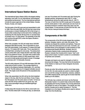
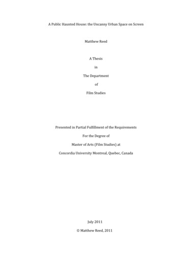
considered enabling for a set of high-value midterm science targets. Medium-priority technologies are those that willenhance or enable missions that are not perceived as critical as those benefiting &om the high-priority technologies,but are still important and need significant funding.The scope nf ISP Techo”!ngy developxent begins at Technolagy Readiness Level (TRL) 3 and continues until aTRL of 6 where that is possible, through ground, or, if appropriate, flight demonstrations. Table 2 providesTechnology Readiness Level definitions.TechnicalReadiness onsBasic principles observed and reportedTechnology concept or application formulatedAnalytical and experimental critical function orcharacteristic proof-of-conceptComponent or breadboard validation in laboratoryenvironmentComponent or breadboard validation in relevantenvironmentSystedsubsystem model or prototype demonstration ina relevant environment (ground or space)Systemprototype demonstration in a spaceenvironmentActual system completed and “flight-qualified”through test and demonstration (ground or space)Actual system “flight-proven” through successfulmission operationsII. AerocaptureAerocapture uses a planet’s atmosphere to accomplish a quick, near-propellantless orbit capture-the placementof a space vehicle in its proper orbit. The atmosphere is used as a brake to slow down a spacecraft, transferring theenergy associated with the vehicle’s high speed into thermal energy.The aerocapture maneuver starts with a hyperbolic trajectory into the atmosphere of the target body. Theatmosphere’s density creates friction, slowing the craft and allowing it to be captured into an elliptical orbit.Onboard thrusters are then used to circularize the orbit.Atmospheric EntryThis nearly fuel-fiee method of decelerating a space vehicle could reduce Hyperbo,,clmerfacethe typical mass of an interplanetary spacecraft by more than half, allowing g;pp;;for a smaller and less expensive launch vehicle and for faster trip times. Infact, aerocapture, when combined with solar electric propulsion technology,enables missions to outer planet destinations that would be impractical usingconventional propulsion.The requirement to slow down a spacecraft by using drag can beachieved in two ways. The craft can be enveloped by a structure andprotected by a rigid heatshield or aeroshell. Such rigid aeroshells are aModulationrelatively mature technology used on Apollo return, Mars Viking, PioneerAtmosphere Ex&Venus, Galileo, Mars Pathfinder and the Mars Exploration Rovers. Anotheroption is for the vehicle to deploy an aerocapture inflatable deceleration Figure 1 Aerocapture Maneuversystem commonly called a ballute-a combination parachute and balloonmade of thin,durable material.2American Institute of Aeronautics and Astronautics
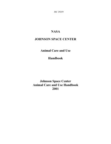
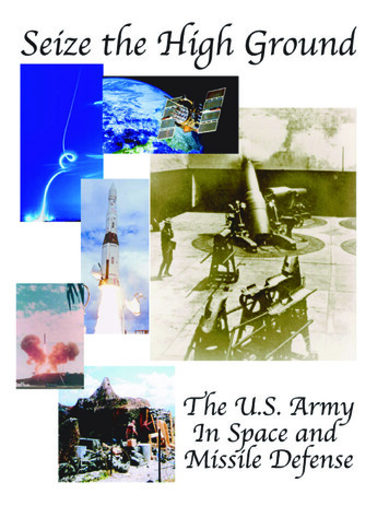
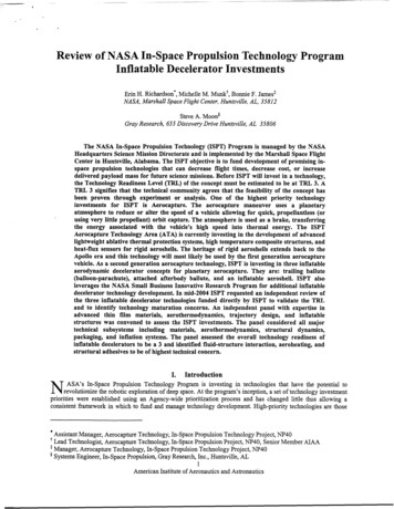
A. Rigid Aeroshell InvestmentsThe rigid aeroshell system encases a spacecraft in a protective shell. This shell provides an aerodynamic controlsurface and a means of protection from the high heatingexperienced during high-speed atmospheric flight. Once aspace vehicle is caphred into orbit, the aeroshe!! isjettisoned.A traditional aeroshell consists of three main parts: (1)the external thermal protection material; (2) adhesives,which are used to bond the thermal protection system(TpC) t the s dc*&-e; z d (3). &;%-kgg!t;-ic;h-a tfiwhich the internal spacecraft and the external thermalprotection material are attached. The challenges toimproving this approach are to customize the design andthickness of the thermal protection material toaccommodate different heating characteristics enduredduring aerocapture, and to develop adhesives capable of Figure 2 Aerocapture of a Rigid Aeroshell Systemwithstanding extremely high temperatures. Rigid aeroshell at Marssystems use lift to change their trajectory during anaerocapture maneuver. By flying at trim angle of attack and using bank angle modulation, the vehicle is able toadjust its trajectory and exit the atmosphere at the proper conditions to ensure orbit capture.In FY2003 NASA awarded five rigid aeroshell technology development contracts as part of the ISPT Cycle 1NASA Research Announcement (NRA). Cycle 1 investments are developing several alternative approaches tostructures and TPS for s m a l l body aerocapture missions. These can be combined in different ways for use inWerent environments. The Cycle 1 investments can be categorized as:i) “Warm structures” development using new adhesives and resins that allow the bondline (i.e., the interfacel”structures to go to higher temperatures (from approximatelybetween TPS and structure) of “ t r a d i t i composite250 C up to 325’C or 400 C). In this case, a separate TPS is still bonded to the facesheet of the structure. This workis being pdormed under two separate awards to the NASA Langley Research Center and Lockheed MartinAS OMUin Denver, C S Colorado.ii) “Hot shctures” development using Carbon-Carbon (C-C) in new construction methods to improve theheatshield concept used on the Genesis sample return capsule, making the system lighter. In this case, the C-Cfacesheet sees the heat load and there is no separate TPS bonded to the face of the structure. This work is beingperformed under an award to Lockheed Martin A S O M inU Denver, C S Colorado.iii) Thermal Protection Systems development focusing on detailed response models and material characterizations work is hehg performed 1mler two s q m t eawards to &e NASA h i s s Xesearchof different TPS systems. mCenter and Applied Research Associates in Englewood, Colorado.thick, lightweight heat flux sensors for use iniv) Sensors development producing 12-mm diameter by 0.75depth in TPS. The task involves extensive arcjet testing, and integration with different TPS materials. This work isbeing performed under an award to ELORET CoIporation in Sunnyvale, California and the NASA Ames ResearchCenter.B. Inflatable Decelerator InvestmentsThe rigid aeroshell is considered the first generation Aerocapture technology. The second generation technologyis the inflatable decelerator. The Aerocapture Technology Area is currently investing in three inflatable deceleratorsystems: the trailing ballute, the afterbody attached ballute, and the forebody attached inflatable aeroshell.The trailing ballute features an inflated toroid that is much larger than the spacecraft it is towed behind and isused similarly to a parachute to slow the vehicle. The toroid shape was selected to allow the hole in the toroid to“swallow” the spacecraft wake. Approximately 24 hours before the spacecraft interfaces with the planetaryatmosphere, the ballute is deployed and allowed to fully inflate. This precludes problems the system wouldencounter during inflation in the atmosphere. The trailing ballute design allows for easy detachment and minimizesintderence with the spacecraft’s operation. Trajectory control is simply through drag modulation. When thespacecraft achieves a predetermined deceleration, the ballute is released, allowing the spacecraft to exit theatmosphere. A propulsive periapsis raise maneuver is required to circularize the orbit. The trailing ballute is beingdeveloped by Ball Aerospace and Technologies Corporation in Boulder, Colorado under an ISPT Cycle 1 NRAaward.3American Institute of Aeronautics and A S O M U C S
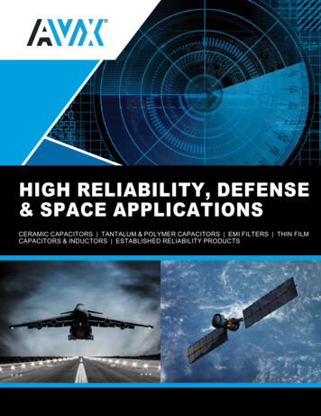
The afterbody attached ballute is much like the towed ballute except that the ballute is attached directly to theback of the spacecraft. Again trajectory control is through dragmodulation and the ballute is released when a certain deceleration isachieved. The afterbody attached ballute is being developed by BallAerospace and Technclogies Corporation in Bodder, Cdorado mdei anFY2004 ISPT NRA Cycle 2 award.The forebody attached inflatable aeroshell is more evolutionary tothe rigid aeroshell. The inflatable aeroshell is often referred to as ahybrid system, with a rigid foreshell and an inflated, attached ballute xteii&g huni &G froni ol“ h e spawxral‘i. Tiajwiury wniroi Cor &einflatable aeroshell will incorporate lift and drag, like the rigid aeroshell9Figure 3 Trailing Ballutesystem; therefore the characterization that the system is moreevolutionary than the drag-only modulated systems. The forebody attached inflatable aeroshell is being developedby Lockheed Martin Astronautics in Denver, Colorado as part of an FY2004 Research Opportunities in SpaceScience (ROSS) Cycle 2 NRA award.Inflatable decelerator systems provide performance advantages over the rigid aeroshell design. One suchadvantage is that the payload does not need to be enclosed in a rigidaeroshell system during interplanetary cruise. Eliminating the rigidaeroshell allows the spacecraft payload to take full advantage of thevolume available in the launch vehicle shroud due to packagingefficiencies enabled by the inflatable systems. Also, with a rigidaeroshell design, the system must fly low into the atmospheresubmitting the spacecraft to sigmficant entry heating, but, with theinflatable decelerator designs, the spacecraft stays very high in theatmosphere where the density is much less and heating can be anorder of magnitude (or more) lower, allowing any protection around i 4 Afterbody Attached BallUtethe payload to be very lightweight.The Aerocapture Technology Area also leverages the Small BusinessInnovative Research (SBR) Program for technology development.Currently the ATA is managing an FY2003 S B R Phase 11 award forthe development of a raked hypercone concept. This concept is beingdeveloped by Vertigo, Incorporated in Santa CIUZ,California. Thiseffort is investigating shape morphing the inflatable aeroshell as ameans of trajectory control. The ATA is also managing a FY2004SEE ? h e I awzd fer the deve!epme t of m “P,eroelas ;,cSimulation Tool for Inflatable Ballute Aerocapture” by CFD ResearchCorporation in Huntsville, Alabama.Figure 5. Forebody Attached InflatableAeroshellIII.Independent Review of Inflatable DeceleratorInvestmentsIn the summer of 2004 the ISPT Program convened a panel ofindependent experts to review and assess current inflatable decelerator investments. An independent expert, for thepurposes of this review, was defied as an expert not currently being funded by ISPT to participate in inflatabledecelerator technology development and not currently working in the same area as a person who was being fundedfor such. The objective of the review was to assess the Technical Readiness Level (TRL) of inflatable deceleratorsystems (trailing ballute, afterbody-attached ballute, forebody-attached inflatable aeroshell) for planetaryaerocapture at small bodies, to identify the most Mfortant subsystem level technologies requiring investment, and toassess the Advancement Degree of Difficulty (AD ) for each technology. If the AD2 was determined to be high orthe TRL was determined to be too low, the ISPT Program may have decided to stop investment in inflatabledecelerator technology development.Experts in the fields of thin film material structures, scientific balloon design and development, aerodynamicsand aerothermal analysis, trajectory control, and advanced spacecraft propulsion were selected to participate on thepanel.4American Institute of Aeronautics and Astronautics
The panel assessed all three concepts being funded directly by the ISPT but, as the contract for the forebodyattached inflatable aeroshell had been awarded late in the summer of 2004, little technology development could bepresented for review.The panel assessed the TlU for each concept and reviewed nine subsystem-level technologies: materials,aerothermodynamics, fluid structure interface, packa @g and storage, trajectory control, structural design,manufacturing, tethers, and inflatioddeployment. The panel assessed the TRL for the trailing and attached ballutedesigns to be TRL 3 and the TFS for the more evolutionary inflatable aeroshell to be TRL 4. The major issuesidentified by the panel included fluid structure interface modeling and analyses, aeroheating, structural stability andstructural adhesives.iden ;f;.ed by the Afz bl: r'ece!etn cr .'e.,,e!cp t?"hid *dcwze n.cp p d p l ; n n z.1pa!;mp: b.1teams as a major concem. Tools do not exist to model thin film structures in a rarefied flow and ground testcapabilities do not exist to adequately verify all aspects of the modeling performed. Currently teams are approachingthe problem by modeling the floflield and the resulting structural response at one point in time, then iterating todetermine the effect of the deformed structure on the flowfield. This interaction continues throughout theaerocapture. Although this is the best approach available, it is time consuming and may not capture all aspects of theinteraction. The panel identified this as a top concem and recommended that a tool be developed that could be usedby multiple concepts. The CFD Research Corporation tool in development under the SBIR Program is expected toprovide a modeling capability but a flight test is considered the only way to verify the modeling performed.Aeroheating is also a known concem. The panel focused on aeroheating on the tethers of the trailing ballute. Thetrailing ballute team has since performed more sophisticated analyses of tether heating and has added thermalprotection to alleviate the heating effects.The major structural concern of the panel was buckling of the ballute systems. The internal pressure for theilm ballute is significantly higher than the maximum dynamic pressure expected upon aerocapture attrailing thin fTitan, but is still much less than 100-Pa. This very low pressure concerned the panel and a recommendation wasmade to perform more thorough analyses to verify the ballute would not buckle.During deep-space missions, inflatable decelerators will be exposed to very cold temperatures (-100 C)for verylong periods of time (on the order of 10 yrs). The panel was concerned that the long term exposure to cold and thenthe rapid temperature increase to 500 C within 10 minutes would present insurmountable challenges to the adhesivesystems. The panel recommended performing a comprehensive long term materials test program to identify andaddress these potential problems.The panel assessed the AD2 for each of the nine subsystem technologies. The AD2 definitions are included inTable 3. The panel concluded that the AD2 for the technologies needed for inflatable decelerator development wereall 2 or less, meaning that the technology challenges could be overcome with a moderate degree of difficulty.ACbOW!C!dpC!Eltrt,sThe work descriied in this paper was fhded in whole or in part by the In-Space Propulsion TechnologyProgram, which is managed by the NASA Science Mission Directorate in Washington, D.C.,and implemented bythe In-Space Propulsion Technology Projects Office at Marshall Space Flight Center in Huntsville, Ala. Theprogram objective is to develop in-space propulsion technologies that can enable or benefit near and mid-termNASA space science missions by significantly reducing cost, mass or travel times.The authors wish to express our thanks to the Technology Review for Aerocapture Inflatable Decelerators panelmembers, Dr.Robert Frisbee, Chairman, for their outstanding effort and exceptional support during the review.5American Institute of Aeronautics and AStrOMUtiCS
.Table 2. Advancement Degree of Difficulty (AD’)1Very low degree of difficulty anticipated in achieving research and developmentobjectives for this technology; only a single, short-duration technological approach needed tobe assured of a high probability of success in achieving technical objectives in later systemsapplications.2Moderate degree of difficulty anticipated in achieving R&D objectives for this technolog;a single technological approach needed; conducted early to allow an alternate approach to bepursued to be assured of a high probability of success in achieving technical objectives inlater systems applications.3High degree of difficulty anticipated in achieving R&D objectives for this technology; twotechnological approaches needed; conducted early to allow an alternate subsystem approachto be pursued to be assured of a high probability of success in achieving technical objectivesin later systems applications4Very high degree of difficulty anticipated in achieving R&D objectives for this te
space propulsion technologies that can decrease flight times, decrease cost, or increase . packaging, and inflation systems. The panel assessed the overall technology readiness of . heatshield concept used on the Genesis sample ret