Transcription
A Guide toShip’s Electro-TechnologyPart 1For Marine Engineers and Electrical Officers
2Marine Insight A Guide to Ship’s Electro-Technology: Part 1Publication date: Oct’ 2013Editor: Raunek KanthariaPublished by: Marine Insight www.marineinsight.comGraphic Design: Anish WankhedeCopyright 2013 Marine InsightNOTICE OF RIGHTSAll rights reserved. No part of this book may be rewritten, reproduced,stored in a retrieval system, transmitted or distributed in any form ormeans, without prior written permission of the publisher.NOTICE OF LIABILITYThe authors and editors have made every effort possible to ensure theaccuracy of the information provided in the book. Neither the authorsand Marine Insight, nor editors or distributors, will be held liable forany damages caused either directly or indirectly by the instructionscontained in this book, or the equipment, tools, or methods describedherein.
CONTENT1. Electricity on Ships - PurposePOWER GENERATIONHIGH VOLTAGE SYSTEMSELECTRICAL PROPULSION SYSTEMS2. Electrical InstrumentsCONSTRUCTION AND WORKING- MEGGERPERMANENT MAGNET MOVING COIL (PMMC)- WORKING AND APPLICATIONRECTIFIER AND RECTIFIER CIRCUITSAMPLIFIER AND AMPLIFIER CIRCUITSTHERMOCOUPLES3. Electrical SafetySAFETY DEVICES ON MAIN SWITCH BOARDELECTRICAL SHOCK- SAFETY AND PRECAUTIONSELECTRICAL FIRE AND INSULATIONGENERATOR SAFETYBLACKOUT SITUATION4. Electrical MaintenanceEARTH FAULTELECTRICAL RELAY MAINTENANCEELECTRICAL MOTOR OVERHAULINGELECTRICAL STARTER PANEL ROUTINEBUSBAR MAINTENANCEALTERNATOR MAINTENANCE3
4ELECTRICITY ON SHIPSA ship is an independent floating structure having itsown power plant for supplying electricity to itsmachinery and systems, which together assist in thepropulsion of the ship from one port to another.POWER GENERATION ON SHIPS: A ship is equivalent to a floating city that enjoysalmost all privileges available to any operational set-up on land. Just like any conventionalcity, the ship also requires the basic amenities to sustain life on board, the chief among thembeing power or electricity. Electricity on ships is generated by an alternator or generator.Shipboard power is generated when a primemover and alternator works together. Forthis purpose, an alternating currentgenerator is used on board. The generatorworks on the principle that as a magneticfield rotating around a conductor varies, acurrent is induced in the conductor.The generator consists of a stationary set ofconductors, wound in coils of iron core alsoknown as the stator. A rotating magnetknown as rotor turns inside this stator,producing a magnetic field, which cutsacross the conductor and generates aninduced EMF or electro-magnetic force as
5the mechanical input causes the rotor toturn. The magnetic field is generated byinduction (in a brushless alternator) and by arotor winding energized by DC currentthrough slip rings and brushes. Few pointsthat are to be noted about power generatedon board ships-AC, 3-phase power is preferred over DC asit gives more power for the same size- 3-phase is preferred over single phase as itdraws more power and in the event offailure of one phase, other 2 can continueworkingPower Distribution on Ships:Th ship’s pow distribution systemconsists of different components fordistribution and safe operation of thesystem. The main components of thissystem are: Ship’s generator - consists of primemover and alternator Main switchboard - a metal enclosuretaking power from the dieselgenerator and supplying it to differentmachinery systems Bus bars - acts as power carrier andallows transfer of load from one pointto another Circuit breakers - act as a switch, andin unsafe conditions can be tripped toavoid breakdown and accidents Fuses - safety devices for machinery Transformers - to step up or stepdown the voltage. When supply is tobe given to the lighting system, a stepdown transformer is used in thedistribution systemIn a power distribution system, thevolt g t which th ship’ s l ct ic lsystem works is usually 440v. However,there are some large installations whereinthe voltage is as high as 6600v.Power on ships is supplied through circuitbreakers to large auxiliary machinery athigh voltage. For smaller supply fuse andminiature circuit breakers are used.The power distribution system, consisting ofthree wires, can be neutrally insulated orearthed. Insulated system is more preferredas compare to earthed system, as during anearth fault essential machinery such assteering gear can be lost.Emergency Power Supply:In case of failure of the ship’s main powergeneration system, an emergency powersystem or a standby system is used. Theemergency power supply ensures that theessential machinery systems continue tooperate the ship.Batteries or an emergency generator or evenboth can supply emergency power on ships.Ratings of the emergency power supplyshould be such that it is able to support allessential systems such as: Steering gear systemEmergency bilge and fire pumpsWatertight doorsFire fighting systemShip’s navigation lights andemergency lights Communication and alarm systems
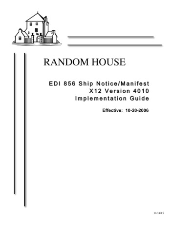
6HIGH VOLTAGE SYSTEMS ON SHIPS: As thship’s siz nd c p city inc s s,bigger machinery/ equipment are installed to ensure its operational efficiency; however highvoltage is used only for few important machinery systems.Usually a 3phase, 60Hz, 440 Volts supply isgenerated and distributed on board ships. Asthe ship size increases, there is a need toinstall more powerful engines and othermachinery systems. This increase in size ofequipment demands more electrical powerand higher voltages.Any voltage used on ship, if less than 1kV(1000 V) is called as LV (Low Voltage)system and any voltage above 1kV istermed as high voltage system.Typical Marine HV systems usually operateat 3.3 kV or 6.6 kV. Passenger liners suchas QE2 operate at 10kV.Why High Voltage on Ships?Let us assume that a ship generates 8MW ofpower at 440V, from 4 diesel generator setsof 2MW, 0.8 power factors each.Each generator feeder cable and circuitbreaker has to handle a full-load current of:I 2 * 106/ ( 3 * 440 * 0.8)I 3280.4 Amps (Approximately, 3300Amps)The protection devices such as circuitbreaker should be rated at approximately90kA for each feeder cable.Let us now calculate the current if thegenerated voltage is 6600Volts.Image Credit: WilhelmsenI 2 * 106 / ( 3 * 6600 * 0.8)I 218.69 Amps (Approximately 220Amps.)Thus the protection devices can be rated aslow as 9 k Amps.Also, Power Loss I2 * rWhere, I - the current carried by theconductor, R - the resistance of theconductor.The power loss varies square of the currentcarried by the conductor. If the supplyvoltage is 440V, then the current carried bythe conductor is 0.002P, and if the voltage israised to 6600V, then the current carried forthe same power is (1.515 *(10 -4)) * P.Thus it implies that the power loss isreduced by a greater extent if the voltage isstepped up. Also, it is always efficient totransmit power at a higher voltage.Conversely, reducing the resistance of theconductor can reduce the power loss.r ρ * l/a.
7By increasing the cross-sectional area of theconductor (diameter), the resistance of theconductor and the power loss can bereduced.But this involves huge increase in costs andsize/ weight of cables, requiring additionalsupports. This method is therefore not usedto reduce the power loss duringtransmission and utilization.Also, it is not necessary to a have bigger sizemotor for high voltage systems. This meansthat the motor can be of a smaller size even ifit’s designed for 6600 Volts as compared tothat of 440Volts.Thus, most of the new ships are fitted withhigh voltage systems.Electrical Propulsion System: The conventional propulsion system of ships is efficientbut requires high operating costs and increases marine pollution. Among all prospectivealternate power sources for ships, electrical propulsion system is one of the most promisingalternatives in tod y’s tim .
8Understanding the SystemApplicationsThe electric propulsion system consists ofa prime mover, which can be of two types:- Diesel drivenThough electrical propulsion is normallyused for smaller vessels, shippingcompanies are now adopting this systemfor big size cargo vessels as well.- Turbine or steam drivenElectrical propulsion is fitted in:Both these systems produce less pollutionas compared to conventional marinepropulsion system, which involves burningof heavy oil. Tugs and trawlersThe propeller shaft of the ship is connectedto large motors, which can be D.C or A.Cdriven, also known as propulsion motors. Cable laying shipsShip’s g n to nd p im movassembly supplies power for the propulsionmotor.Arrangement and OperationThe generator can be direct or alternatingcurrent type with diesel or steam drivenprime mover, depending on therequirements or demands of theowner/ship.In the electrical propulsion system, thedirection of the propeller rotation isgoverned either by the electrical control ofthe motor or by changing the electricalsupply.Normally variable speed electrical motor isused for fixed pitch propeller system andconstant or variable motor can be used forvariable pitch propeller or CPP. Dredgers Dynamic positioning vessels Ice breakers Research ships Floating cranes Offshore VesselsAdvantages of electrical propulsionsystem are: A large amount of power isgenerated by the system and theexcess power can be utilized bysupplying it to cargo pumps, firepumps and other important auxiliarymachinery The space required for installation ofelectrical propulsion machinery isless and compact as compared toconventional systems There is no direct connection of
9propeller shaft and prime mover andhence transmission of severe stressessuch as torsional and vibration isreduced There is more flexibility ininstallation of machinery It provides improvedmaneuverability and highredundancy Increased payload through flexiblelocation of machinery components Environmental benefits from lowerfuel consumption and emissions High performance in tough iceconditions due to maximum torqueat zero speed Reduces lifecycle cost by less fuelconsumption and maintenance costs Better comfort due to reducedvibration and noiseDisadvantages of this system: The efficiency of electrical plant isless than that of conventional system The installation cost of electricalpropulsion plant is much higher Imp ovis d t ining fo ship’s c wis required as the system iscompletely different frommechanical system and involvesmajor automationFrom long-term perspective, electricpropulsions systems are promising powersources for ships, considering their highefficiency and stringent marineenvironmental norms.Know the Complete Operating Procedureof Ship’s P opulsion Pl nt nd OthAuxiliary Machinery Systems. DownloadOur eBook-“The Ultimate Guide toOperating Procedures forEngine Room Machinery”
10ELECTRICAL INSTRUMENTSThe ship consists of series of electrical wires andequipment, which are responsible for running itsmachinery systems. For periodic inspectional and upkeeping of the electrical system onboard ships, a varietyof electrical instruments are used.MEGGER- CONSTRUCTION AND OPERATION: The most important routinemaintenance for electrical machinery involves checking of insulation resistance, which is doneby n inst um nt c ll d “M gg ” o “ohmm t ”.Insulation Resistance:Insulation resistance (I.R) is a criticalp m t s it’s di ctly l t d topersonal safety, safety of machinery andpower reliability. The I.R value of anelectric device changes with aging,mechanical and electrical stresses,temperature, contamination, atmosphere,humidity etc. It is therefore important forseafarers to check this parameter foravoiding fatal accidents due to electricalshock.
11Megger or Ohmmeter:Megger is a portable instrument used tomeasure insulation resistance of electricalmachinery or system. It is battery operatedor mechanically operated (hand crank dcgenerator) and gives direct reading inohms. Megger is used to measure voltageratings in the range of 100V to 5000V.Construction:A Megger consists of following parts:1) Control and Deflecting coils: Theyare normally mounted at right angleto each other and are connectedparallel to the generator. Thepolarities are such that the torqueproduced by them is in the oppositedirection.2) Permanent Magnet: Permanentmagnet with north and south polesare used for construction toproduce magnetic effect fordeflection of pointer.3) Pointer and scale: A pointer isattached to the coils with its endfloating on a scale ranging from“z o” to “infinity”. Th unit fo thisis “ohms”.4) D.C generator or batteryconnection: Hand operated D.Cgenerator supplies testing voltage formanually operated Megger. Inautomatic type Megger, testingvoltage is supplied by battery andelectronic voltage charger5) Pressure coil and currentcoil: They are provided forpreventing damage to the instrumentin case of low external sourceresistance.
12Working The voltage for testing is supplied bya hand generator incorporated in theinstrument or by battery or electronicvoltage charger. It is usually 250V or500V and smaller in size A test volt of 500V D.C is suitablefo t sting ship’s quipm ntoperating at 440V A.C. Test voltageof 1000V to 5000V is used for highvoltage system onboard The current carrying coil (deflectingcoil) is connected in series andcarries the current taken by thecircuit under test. The pressure coil(control coil) is connected across thecircuit Current limiting resistor – CCR andPCR are connected in series withpressure and current coil to preventdamage in case of low resistance inexternal sources In hand generator, the armature ismoving in the field of permanentmagnet or vice versa, to generate atest voltage by electromagneticinduction effect With an increase of potential voltageacross the external circuit, thedeflection of the pointer increasesand with an increase of current, thedeflection of pointer decreases.Thus, the resultant torque on themovement is directly proportional tothe potential difference and inverselyproportional to the resistance When the external circuit is open,torque due to voltage coil will bemaximum and the pointer will read“infinity”. When there is shortcircuit, th point will d “0”
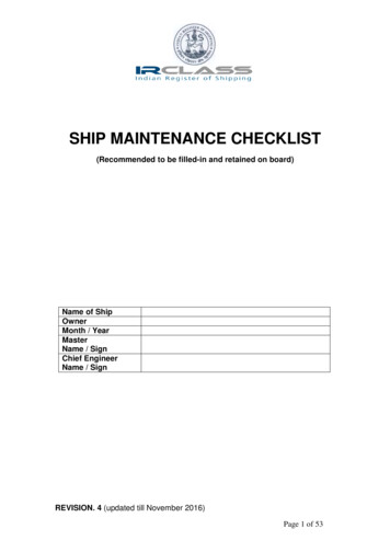
13PERMANENT MAGNET MOVING COIL INSTRUMENT (PMMC): Variety ofinstruments are used onboard for measuring parameters of electrical machinery and systems. Apermanent magnet moving coil (PMMC) is one such instrument which is popularly usedonboard for several applications.Principle of Operation:When a current carrying conductor isplaced in a magnetic field, it experiences aforce and tends to move in the direction asp Fl ming’s l ft hand rule.“If the first and the second finger and thethumb of the left hand are held so that theyare at right angle to each other, then thethumb shows the direction of the force onthe conductor, the first finger pointstowards the direction of the magnetic fieldand the second finger shows the directionof the current in the wire.”Construction:A coil of thin wire is mounted on analuminum frame (spindle) positionedbetween the poles of a U shaped permanentmagnet made of magnetic alloys such asalnico.The coil is pivoted on the jeweled bearingand is free to rotate. The current is fed tothe coil through spiral springs, which aretwo in numbers. The coil current, which isto be measured, moves in a strongmagnetic field produced by a permanentmagnet and a pointer is attached to thespindle to show the measured value.Image Credit: tpub
14When a current flows through the coil, itgenerates a magnetic field that isproportional to the current when used as anammeter. The deflecting torque isproduced by the electromagnetic action ofthe current in the coil and the magneticfield.The controlling torque is provided by twophosphorous bronze flat-coiled helicalsprings. These springs serve as a flexibleconnection to the coil conductors.The eddy current set up in the aluminumcoil dampens the oscillation.Applications:The PMMC has a variety of uses onboardship such as:1) Ammeter:When PMMC is used as an ammeter,except for a very small current range, themoving coil is connected across a suitablelow resistance shunt, so that only smallpart of the main current flows through thecoil.The shunt consists of a number of thinplates made up of alloy metal, which isusually magnetic and has a lowtemperature coefficient of resistance, fixedbetween two massive blocks of copper. Aresistor of same alloy is also placed inseries with the coil to reduce errors due totemperature variation.2) Voltmeter:When PMMC is used as a voltmeter, thecoil is connected in series with highresistance. Rest of the function is same asabove. The same moving coil can be usedas an ammeter or voltmeter with aninterchange of above arrangement3) Galvanometer:Galvanometer is used to measure smallvalue of current along with its directionand strength. It is mainly used onboard todetect and compare different circuits in asystem.5) Ohm Meter:The ohmmeter is used to measureresistance of the electric circuit byapplying a voltage to a resistance with thehelp of battery. A galvanometer is used todetermine the flow of current through theresistance. The galvanometer scale ismarked in ohms and as the resistancevaries, since the voltage is fixed, thecurrent through the meter will also vary.Advantages: The PMMC consumes less powerand has great accuracy It has uniformly divided scale andcan cover arc of 270 degree The PMMC has a high torque toweight ratio It can be modified as ammeter orvoltmeter with suitable resistance It has efficient dampingcharacteristics and is not affected bystray magnetic field It produces no losses due tohysteresis
15Disadvantage: The moving coil instrument can only be used on D.C supply as the reversal of currentproduces reversal of torque on the coil It is very delicate and sometimes uses AC circuit with a rectifier It is costly as compared to moving coil iron instruments It may show error due to loss of magnetism of permanent magnetTHERMOCOUPLES: Thermocouple is a device widely used as a pyrometer on board shipsfor continuous measurement of temperature for machinery systems such as main engine,auxiliary engine, gas turbines etc.It is absolutely important to choose thecorrect thermocouple material for differenttemperature range operations, dependingupon the machinery and thermocouplelocation where the parameter has to bemeasured.Construction of Thermocouple:A thermocouple consists of two dissimilarhomogeneous materials connectedtogether. The materials used depend uponthe application and usage. Normally,following materials are used for differenttemperature ranges:ceramic sheath covered again by a metalsheath and are fitted at desired locationssuch as exhaust manifold etc. One end of thethermocouple is placed in hot junction andother end is kept in a constant cold junction.These materials are led to a temperatureindicator through an amplifier andcompensator lead. The amplifier andcompensator lead (normally made up ofcopper and does not effect the circuit) helpsin transmitting the output to a remotelocation.Principle & WorkingCopper – Constantan (copper nickel alloy)for range of –200 to 400 CThermocouple works with the principle of“s b ck ff ct” which st t s th t-Iron – Constantan for temperature range of 40 to 750 C“Temperature between two dissimilarmetals in a circuit converts intoelectric current”Chrome – Alumel (alloy of nickel,manganese, aluminium and silicon) fort mp tung of 200 to 1350 C.These materials are connected together in aWhen two dissimilar metal wires, supposeiron and constantan, are coupled togetherand exposed to difference in
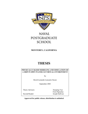
16temperatures at both the ends, EMF isgenerated and the current flows from hot tocold side.The magnitude of the current depends onthe temperature difference between thejunctions. If one junction is kept atconstant temperature, then the value oftemperature for the other junction can beeasily determined.Advantages of Thermocouple Can be used for remote temperaturesensing Temperature difference can bemeasured with high accuracy Can be used for continuoustemperature sensing They are inexpensive and easilyinterchangeableRECTIFIER AND RECTIFIER CIRCUITS: Since most of the ships generate A.C currentfrom its alternator, it becomes essential to use a device, along with the transformer, that canconvert this A.C current into D.C current for using equipment or circuit running on directcurrent. Rectifier is a circuit, which utilizes one or more semiconductor diodes to convert analternating current into a pulsating direct current.All electrical and electronic equipment orcircuits on board ships play a vital role inthe op tion of ship’s m chin y systems.Equipment onboard vessels utilizealternating current, direct current or bothdepending upon the nature of operation.Some of the important circuits and setupsare run through D.C current. Hence it isimportant to convert the generated A.Ccurrent in to D.C current and this processof conversion is known as rectification.Rectifiers are used for this purpose.Half Wave Rectifier
17Types of RectifiersIt is commonly used in three phase circuits.Half wave rectifier:Half wave rectifier consists of a single diodeconnected in series with the load resistor.During the positive half cycle of inputvoltage, the diode is forward biased andconducts for all voltages greater than itsbarrier potential.During negative half of the cycle, the diodeis reverse biased hence it does not conduct.Full wave rectifier:Full wave rectifier circuit allowsunidirectional current to flow to the loadduring the entire input cycle. There are twotypes of single full wave rectifier:Full Wave Rectifier- Two diodes connected back-to-backusing a center-tapped transformer.- Full wave bridge rectifier using fourdiodes connected in the form ofbridge.Bridge rectifier:A single-phase bridge rectifier is used withfour diodes connected in bridge with a noncenter tapped transformer.Full wave rectifier has an advantage ofconverting both polarities of input A.Cwaveforms into D.C and therefore it is moreefficient.A three-phase rectifier circuit consists of sixdiodes, which are in pair of three, connectedin series (anode to cathode).Bridge Rectifier
18Applications onboardSome of the uses of rectifiers on board ships are: Used in marine electronic devices and circuits Used for onboard battery charging from the ship supply Used in detection of radio signals Used in electroplating process Used in ship construction for electrolyte refining of metals Used in operation of D.C motor Used in field excitation of three-phase alternatorAMPLIFIER AND AMPLIFIER CIRCUITS: An Amplifier or an operational amplifier(op-amp) circuit is commonly used in the automation, control and other electronic circuits ofmarine applications. The applied input signal is normally a voltage or a current signal. Thepurpose of an amplifier is to produce an output signal larger than that of the input signal.Purpose of Amplifier:As the name suggest, the purpose of anamplifier or an op amp is to amplify orincrease the input signal to produce anoutput signal, which is much larger thanthat of the input, with a similar waveformas that of the input.The main change in the output signal willbe the increase in the power level. Thisadditional power is supplied by a D.Cvoltage, which is externally provided. Theoutput signal is controlled by the inputsignal in an amplifier.
19converter and vice-versaOperation of Amplifier CircuitThe input of the amplifier consists ofdifferential input voltage V input and Vinput and this difference in the voltage isamplified to produce a larger output. It is used as a servo amplifier inmotors The output signal from amplifier issupplied to a relay in a circuitThe op-amp equation can be given by:V o/p [(V )- (V-)] x A o/lWhere A o/l - is open loop gain of theamplifier.In an op-amp the magnitude of A o/l isvery large which gives a larger output evenwhen the input differential is small.Other important properties It has a high output gain It has high input and low outputimpedance Bandwidth is in very high rangeApplications of Amplifier CircuitAn amplifier circuit is popularly used inmarine electrical/ electronic circuits andapplications such as: It is used to amplify audio signal(loudspeaker, VHF) It is used as voltage and currentregulator It is used as analog to digitalLearn more about all the measuringequipment and tools used on an Oil TankerVessel in our eBook-“The Ultimate Guide to CargoOperation Equipment forTankers”
20ELECTRICAL SAFETYElectrical equipment systems on ships are extremelyhazardous and seafarers must take special care whilehandling them. Personal safety is of utmost importancewhile dealing with electrical systems on ships.ELECTRICAL SHOCK: When we talk about accidents on a ship, an electrical shock is theworst of all kinds. Electrical wires and connections are present everywhere on a ship and it isimportant to prevent yourself and others from getting a major electrical shock.Steps to Minimize the Risk of anElectrical Shock Start with the first round of the day;check all electrical motors, wiring,and switches, for abnormal sounds,variation in temperatures and looseconnections Ensure that all electrical connectionsare inside the panel box so that noone can touch them accidently In accommodation area multiplesock t plugs shouldn’t b used Turn off the breaker before startingany work on an electrical system Use ply cards and notice board asmuch as possible to inform othersabout the ongoing work to avoidccid nt l “st ts” Double check electrical tools such asportable drills for any loose wiresbefore attempting any job Always wear protective clothing,rubber gloves, rubber kneepads andsafety shoes to avoid risk of shock
21 Use electrically insulated handle toolsfor working or checking electricalsystems Before working, remove jewelry,wrist bands and other conductiveitems When working or removing multiplewires, tape off all but the one wireyou are working on Try as much as possible not to workon live system and even if you do so,be a professional and work carefully,taking all necessary safetyprecautions and with utmostconcentration During working in group or pair,organize a tool box meeting anddiscuss the procedure, risk andhazards of the job in hand If you don’t know bout th syst m,ask for assistance. Don’t wo kwithout knowing the system Always think first about yourpersonal safety and safety of fellowseafarers while carrying out anyelectrical work on board shipsMAIN AND EMERGENCY SWITCHBOARD SAFETY: It is very important to isolateany type of fault in an electrical system supplied from the main switchboard (MSB), or else, itwill affect all the other systems connected to the same. If such isolation is not provided thenshort circuit in even a smaller system can cause blackout of the whole ship.The main switchboard is an intermediateinst ll tion in th ship’s pow dist ibutioncircuit, connecting the power generators andpower consumers. The power generators onships are auxiliary engines with alternatorsand the different engine room machineriessuch as motors, blowers etc. are theconsumers.Variety of safety devices are used on boardships and installed on the main switchboard(MSB) and electrical distribution panels.This ensures safe and efficient running ofmachinery systems and safety of theseafarers from electric shocks.
22The Important safety devices fitted onmain switchboard are:the default system. Normally, fuses are usedwith 1.5 times of full load current.Circuit breakers: A circuit breaker is anauto shutdown device, which activatesduring an abnormality in the electricalcircuit. Especially during overloading orshort circuit, the circuit breaker opens thesupplied circuit from MSB and protects thesame. Different circuit breakers arestrategically installed at various locationson the ship.Over current relay: OCR is used mainly onthe local panel and MSB for protection fromhigh current. It is installed where a lowpower signal is a controller. Normally relaysare set equivalent to full load current withtime delay.Fuses: Fuses are mainly used for shortcircuit protection and comes in variousratings. If the current passing through thecircuit exceeds the safe value, the fusematerial melts and isolates the MSB fromDead front panel: It is also a safety deviceprovided on the main switchboard individualpanels, wherein you cannot open the paneluntil the power of that panel is completelyswitched off.Maintenance and operational safety plays animportant role for the overall safety of themain switchboard.ELECTRICAL FIRE SAFETY: The root cause of any electrical fire is the insulation of thecircuit or wire. If the insulation is weak or damaged, it may lead to spark, electrical shock orfire in the system causing major accidents and causality. The best way to avoid electrical fireis to maintain the insulation of electrical wires and equipment.The insulation of the electric cable isgenerally made up of rubber or plastic. Theamount of smoke generated by the plasticin case of fire is dependent on factors suchas nature of plastic, type of additive used,flame of fire and ventilation arrangements.In general, most plastics produce a verydense smoke when heated.Some plastic burns very clearly whensubjected to heat and flame, producingvery less smoke. If insulation used is ofurethane foam, a very dense smoke isproduced and visibility in the room is lost.Some plastics contain Poly Vinyl Chloride(PVC), which produces pungent, andirritating odor.
23Rubber when used for insulation produces adense, black, oily smoke and has some toxicqualities. The most common gases producedduring combustion of rubber are hydrogensulphide and sulphur di-oxide. Both thesegases are dangerous for health and can be fatalin certain cases.Ways to Reduce these HazardsThe following steps should to taken aspreventive measures:- Cables having E.P.R (Ethylene Pro
of heavy oil. The propeller shaft of the ship is connected to large motors, which can be D.C or A.C driven, also known as propulsion motors. Ship’s g n to nd p im mov assembly supplies power for the propulsion motor. Arrangement and Operation The generator can be direc