Transcription
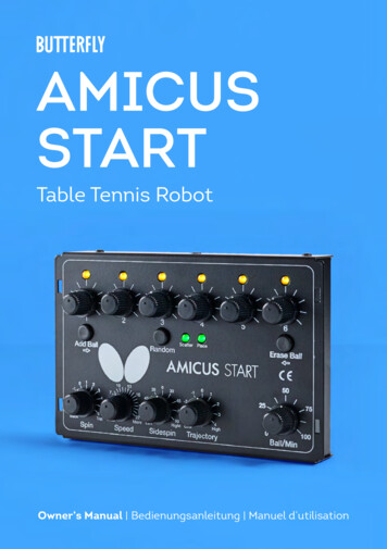
AMICUSSTARTTable Tennis RobotOwner’s Manual Bedienungsanleitung Manuel d’utilisation1
AMICUS START Table Tennis Robot State of the art 3-wheel ball delivery technology provides all types of spin.Rigid sponge wheels with a special coating for longer durability.Compact, solid, functional construction with integral encompassing ball collection net.Lightweight and easily transportable. Weights approximately 6 kg (13 lbs.). User-friendly Control Panel permits quick overall view with easy-to-understand adjustments.Random features include natural scattering of shots, random placement, or both!Adjust height of ball delivery to simulate anything from low serves to high lobs.Regulate all functions with the Control Panel located on the player’s end of the table.Covered by a full 2-year Manufacturer’s Warranty and a 5-year guarantee of parts and service availability. See full warranty information on page 20.CAUTIONS Please read this Owner’s Manual carefully before using the machine.This machine may only be connected to 100-230V voltage.The ball throw wheels rotate at high speed. Avoid touching the wheels during operation!Use this product only in enclosed and dry rooms.Used properly, your AMICUS START will always be a great training partner and friend(AMICUS is Latin for Friend).2
IMPORTANT: Please read instructions carefully prior to use!The Control Panel chapter describes basic adjustments of the AMICUS START table tennis robot.More detailed instructions can be found in the Operation chapter.Contents1. Setup . 42. Control Panel. 63. Operation. 7Nomenclature.7Adjustment Of Head Height. 8Starting Your Robot. 8Balls Thrown To One Placement. 8Balls Thrown To 2 Or More Placements. 9Random Controls. 10The Remote Switch (optional). 10Linking the Remote Switch to the Robot. 11Changing The Battery In Your Remote. 11Take Down, Storage, & Transport.124. Maintenance & Repair.13Cautions.13Checking & Adjusting Wheel Clearance.13Replacing The Wheels.14Ball Jams.15Other Maintenance.165. Troubleshooting. 166. List of Replacement Parts. 187. Technical Data.208. Warranty Information.203
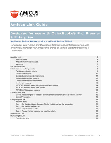
1. Setupa.b.c.d.e.Photo 1ARobot and Net AssemblyPower Supply (Input : 100-240V, Output : 24V DC, 3A)Control PanelControl Panel CableControl Panel Mounting BracketOther parts: Hex wrenches (2 and 4 mm) for wheels, Wheel Adjustment Gauge (black tube with fins), spare rub-ber bands for the SideNets, Velcro strips. White, steel strips to repair of the deflectorplate.1. P lace the robot on top of your table tennis table. Fold downboth sides of the net at the same time until the first stop (Photo1A). Rotate towards you the curved tubular Support Legs intothe position as seen in Photo 1B (about 15–20 cm, or 6-8 in.,apart).Photo 1B2. R otate the entire robot 180 with the Support Legs facing awayfrom you. Grasp the robot with both hands on the bottom ofthe Base. Pick up the robot, angle the Support Legs downward,slip them under the end of your table tennis table, and push therobot onto the end of the table. Gently let go of the base and therobot will hang by its own weight as seen in Photo 2.Please note that AMICUS robots are designed to fit onto 25 mm(1 in.) thick tops. If your top is less than 25 mm thick, you willneed to adjust the support legs using the height adjustingscrews. Turn the screws inward until the thickness differencebetween 25 mm and your particular table surface is sufficientlyequalized.CAUTION: Please use the included longest Velcro strip to helpsecure the robot to the end of the table. This is especially important if children play around the table. The Velcro strip helpsstabilize the robot to prevent it being knocked off the table.3. Loosen the large Black Knob found on the rear of the Ball Tube.Rotate the head 180 and then pull the head upwards until the3rd coloured ring on the tube is just visible (Photo 3A), thentighten the Black Knob to hold it in place (but not too tightly).Lastly, fasten the Head Cable coming from the head to the serialconnector found on top of the Base (Photo 3B).4Photo 2
Photo 3APhoto 3B4. S tanding behind the robot, grip the top points of the net and fold the net down on both sides untilthe net fully opens (as seen in Photo 4A). Fit the plastic Corner Brackets of the net around thecorners of your table as seen in Photo 4B.Photo 4APhoto 4BNOTE: You may attach the two shortest Velcro strips to the corners of your table underneath theCorner Brackets to help the brackets stay down and stabilize the entire net.5. P ull a Side Net along the side line of the table and pass its thick rubber band over the top of thetable’s net standard (see Photo 5A). Then loop the rubber band around the Clamp Screw that holdsthe net onto the table. Attach the Side Net’s Velcro tab to its matching piece located on the CornerBracket as seen in Photo 5B.Photo 5APhoto 5B6. P lug your Power Supply into a power outlet and then into the power jack on the side of the Base.Connect the Control Panel Cable into the jack plug (looks like a headphone jack) on the side of the5
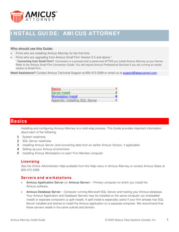
Base (see Photo 6A). Pull the Control Panel Cable to the opposite side of the table and connect itto the Control Panel (see Photo 6B). Next attach the Control Panel Mounting Bracket on the side ofthe table and then hang the Control Panel on the Control Panel Mounting Bracket. You may use aVelcro strip to help secure the bracket onto the side of the table.Photo 6APhoto 6B2. Control Panel1214Add 671Less64Scatter PlaceErase Ball50153094560RightSidespin752530819 452260More LeftSpeed05Low10HighTrajectory0Ball /Min.1001 Ball LEDs (1–6) — When lit and solid, indicates a ball is programmed for that spot. A flashing lightindicates the Current Ball. Number of lit LEDs indicates the number of balls in your Exercise.2 Placement Knobs (1–6) — Sets the left/right placement for that ball. Setting at the 12:00 o’clockposition tells the robot to throw that ball down the centerline. Setting a knob to the left or right of12:00 o’clock tells the robot to throw the ball to the left or right courts, respectively. Setting a knobto the far left or far right tells the robot to throw the ball to the left or right corner.6
3 Add Ball Button — Press this button to add a ball to your Exercise. After pressing, a new ball is addedand its LED starts flashing.4 elete Ball Button — Press this button to delete a ball from your Exercise. Works for Balls 2–6. YouDcannot delete Ball 1.5 Random Button — Press once to select Random Scatter, press twice to select Random Place, and pressa 3rd time to select Random Scatter Place. Press a 4th time to exit. See page 10 for more info.6 Spin Knob — Increases or decreases the amount of backspin or topspin. 0 means no spin. Positivevalues select increasing amounts of topspin. Negative values select increasing amounts of backspin.7Speed Knob — Increases or decreases the speed of the ball.8 S idespin Knob — Shifts the orientation of the sidespin to the left or right. 0 means no sidespin. Positions to the left select increasing degrees of left sidespin. Positions to the right select increasingdegrees of right sidespin.9 Trajectory Knob — Raises or lowers the trajectory (throw angle). 0 indicates the midway point. Positive values indicate higher positions and negative values indicate lower positions.10 Ball/Min knob — Decreases or increases ball frequency (Balls per Minute). Frequency ranges fromabout 6 to over 100 balls per minute. 60 is the average topspin counter rate. 30-45 is often usedfor beginner/novice training. Lower settings can be used for serve return, 3rd ball attack, & otherspecialized drills.3. OperationNomenclatureTo assist in clearly communicating the various features of your robot, it is necessary to define how werefer to certain elements. Here are various terms used throughout this manual:Ball Type — 4 controls affect Ball Type: Spin, Speed, Sidespin, and Trajectory.Ball Placement — the left/right location where a ball lands, determined by the Placement knob.Basic Ball — the ball that is thrown when the Control Panel is first powered on and no adjustments havebeen made. This ball will have no spin with medium speed and height.Current Ball — the ball that is currently selected as indicated by its flashing Ball LED.Ball 1–6 — refers to the Placement Knobs and corresponding Ball LEDs.Exercise — a sequence of between 1 and 6 shots. Also called drill, program, or rally.1–4 Rings — how the head height adjustment is described. E.g., 3- (coloured) Rings would mean the headheight is adjusted so 2 rings (painted on the Ball Tube) are visible (see Photo 7).7
Adjustment Of Head HeightOn most table tennis robots, the height of thehead cannot be adjusted. In contrast, AMICUSEXPERT offers 4 different heights to better simulate realistic play. It is quite easy to adjust thehead height. From be hind the net, push the topof the net down to reach over it. Grab the curvedball tube with one hand and loosen the largeBlack Knob with the other hand (see Photo 7).You can then pull the tube up or push it down toadjust head height. Lock it in place by tighteningthe Black Knob. (Be careful not to tighten theknob too much.)Photo 7IMPORTANT: Before tightening the Black Knob, be sure one of the coloured rings painted on the balltube is right at the top of the lower tube (see Photo 7). Be careful not to tighten the Black Knob tootightly—you can dent the tube if tightened too much. Failure to adjust the head height correctly canresult in ball jams, double throws, missed throws, and other feed issues.Starting Your RobotAfter completing Step 5 on page 5, place about 50 or more 40 or 40 balls into the Ball CollectionTray. The Ball 1 LED should be flashing yellow Turn Ball/Min knob to your desired setting (you will hearthe wheels start spinning) and balls will begin loading into the machine. After a few seconds, the firstball will reach the top of the ball tube. Turn Ball/Min knob to 0 to halt ball feed.Grab your racket and prepare to return balls from your robot. Turn all knobs in middle position, thenturn the Ball/Min knob to your desired setting and observe where the balls land in relation to thecenterline. If balls are delivered either left or right of the centerline, then stop ball delivery. At therobot, loosen the large Black Knob on the rear of the Ball Tube (see Photo 6B) and rotate the head in thedirection necessary for balls to land closer to the centerline. Repeat until all balls are landing close tothe centerline, then turn Ball/Min to 0.Balls Thrown To One PlacementThe easiest way to learn the various controls is to start with a single ball delivered to one location. Onthe AMICUS START, all Balls in an Exercise will have 1 Ball Type (other models allow different Ball Typesfor each Ball). Upon powering on the Control Panel, only the Ball 1 LED should be lit and it should beflashing. If any other Ball LED is lit, press the Delete Ball button until only Ball 1 LED is lit.To adjust Ball Type: T he Trajectory knob (9) raises or lowers the ball trajectory (throw angle). Although there are only9 settings marked on the Control Panel, there are actually about 15 steps of adjustment betweeneach marked increment for a total of over 150 steps of adjustment. This allows you to finely tune theTrajectory from very low for serves, where the ball bounces first on the robot’s side of the net, crosses the net, and then bounces a second time on the player’s side, to high, where the ball is thrown acouple of feet over the net.8
T he Sidespin knob (8) changes the orientation of the sidespin on the ball. The zero setting meansthere is no sidespin on the ball. Each marked increment represents a 15 change in orientation,except for the first mark, which is 30 . Settings to the right of zero are degrees of right sidespin andsettings to the left are degrees of left sidespin. T he Speed knob (7) reduces or increases the speed of the ball. There are 22 increments of speedadjustment, from 1 for very slow, to 22 for very fast. T he Spin knob (6) reduces or increases the amount of spin on the ball. A setting of zero indicatesno spin (dead ball). Settings to the right of zero (1 to 6) indicate stronger and stronger amounts oftopspin. Settings to the left of zero (-1 to -4) indicate stronger and stronger amounts of backspin.To adjust Ball Placement (also called place or location): T he Placement knobs (2) determine the left to right landing spot of each ball. 12:00 o’clockcorresponds with the centerline of the table. Settings to the right of 12:00 correspond with ballsprogressively landing closer and closer to the right corner of the table. Settings to the left of 12:00correspond to balls landing progressively closer and closer to the left corner.To adjust Ball Frequency: T he Ball/Min knob (10) decreases or increases the rate, or frequency, of shots. You can selectsettings from about 6 to over 100 balls/min. When turned to 0, all motors, including the ones for ballfeed and ball throwing, are turned off and go silent.Once you have adjusted the above settings to your liking, turn up Ball/Min to have the robot deliveryour chosen ball type to your chosen location at the desired frequency. If it is not what you want, turnBall/Min to 0 and change the settings until you get the type of shot you want. Then try again. Althoughyou may find it easiest to stop play to make changes to the settings, you can also change settings onthe fly, without stopping play.Balls Thrown To 2 Or More PlacementsOnce you have the Ball Type selected as described in the preceding section, it is a simple matter tohave that same shot delivered to more than one place. To add additional Balls to your Exercise, pressthe Add Ball button. Ball 2 LED will begin flashing, which indicates it is now the Current Ball (and Ball 1LED will stop flashing to indicate it is no longer the Current Ball). To select a different landing spot forBall 2, all you have to do is change the Placement setting.You can continue this same procedure to add up to 6 balls to your Exercise. With each added Ball, youwill notice that the corresponding LED will light up. By looking at the number of Ball LEDs that are lit,you can quickly tell the number of shots in an Exercise.To play your Exercise, turn up Ball/Min, and AMICUS will throw the balls in order, starting with the ballthat has a flashing LED. E.g., if you have 3 balls with lit LEDs and #2 is flashing, AMICUS will throw Ball 2,followed by Ball 3, and followed by Ball 1. Then it will start over with Ball 2. It will continue this order ofthrown balls until you turn Ball/Min to 0.If you want the Exercise to start with a particular Ball each time, be sure to turn off delivery whenthe desired Ball’s LED is flashing. In the above example, if you wanted the Exercise to start with Ball 19
instead of Ball 2, stop the Exercise when Ball 1 is flashing. Upon restarting the drill, Ball 1 will be flashingand will be the first Ball to be thrown.Best practices: Before playing a multi-ball exercise, look at the Ball Placement knob of each Ball witha lit LED to get an idea of where each Ball will be delivered and in what order. Then look at the Ball Typeknobs to determine the type of Ball that will be thrown. This allows you to be prepared for the sequenceof shots and helps you to decide what stroke to use to return the shots.Please note: Because the distance is greater from the robot to the corners of the table than from therobot to the center of the table, AMICUS START automatically varies the length of ball delivery so anExercise runs correctly when it contains mixed placements. This is possible thanks to the built in program and the special placing mechanism.Random ControlsAMICUS START offers 3 types of randomization—Random Scatter, Random Place, and Random Scatter Place. To activate, press the Random button. Your first press selects Random Scatter (the ScatterLED will light up). Press Random a second time and the Place LED will light up (and Scatter LED darkens). Press Random a third time and both Scatter and Place LEDs will light up. Press a fourth time toturn Random off (and both Scatter and Place LEDs darken).Random Scatter is similar to the less precise shots that a human might deliver. Without RandomScatter, the robot typically delivers shots within an area approximately 13 cm (5in.) in diameter. But withRandom Scatter, balls are delivered in an enlarged area of approximately 40cm (16in.) diameter.Random Place requires at least 2 Balls in an Exercise. If there is only a single Ball, the Place LED willnot light up. With Random Place on, the robot will randomly select one of the Placements programmedfor the Exercise and throw the ball there in an unpredictable order. E.g., let’s say an Exercise usesPlacements of Forehand, Center, and Backhand. Without Random Place activated, the order of throwswill always be the same—FH, Center, BH. But with Random Place on, the order could be something likeCenter, FH, BH, BH, FH, Center, etc.Random Scatter Place combines the above two random functions. The landing spots for every Ball areenlarged and the Placements are randomized.Best practices: Avoid programming landing spots that are close to the sideline, end line, or table netwhen using Random Scatter. If you do, many balls are likely to be shot off the side or end of the table orinto the net because of the enlarged area of the landing spots with Random Scatter. When using Random Place, if you want throws delivered to one spot more often than other spots, program more Ballswith the desired placement. E.g., if an Exercise has 4 Balls with one of them placed to the Forehand andthree placed to the Backhand, there is a 1 in 4 chance a ball will be delivered to the Forehand, but a 3 in4 chance a ball will be delivered to the Backhand. Lastly, while Random Place must have at least 2 Ballsin the Exercise, Random Scatter can be used with single ball exercises.The Remote Switch (optional)The small wireless remote (looks similar to an automobile key fob) has a range of 4–5 m (13–16 feet) andhas the following functions:10
1. I f Ball/Min on the Control Panel is set to 0, pushing the top button(Start) of the remote will throw 1 ball (current ball) of the Exercise shownon the Control Panel.2. I f Ball/Min on the Control Panel is not set to 0, pushing the top button(Start) of the remote will cause the exercise shown on the Control Panelto start playing at whatever frequency the Ball/Min is currently set to.The play stops when pushing the (Stop) button.3. P ushing the ( ) button during play will increase the frequency, whilepushing the (-) will decrease the frequency.Linking the Remote Switch to the RobotEach remote is linked to an individual Robot body. This linkage is done at the factory and each Robotand Remote pair is kept together throughout the manufacturing process. In case you buy more Remotes or a new one, you need to link each Remote to your Robot. Here are the steps to perform theLinking procedure:1. H old down the Random button on your control panel until 4 LEDs on the control panel will light up.The 4 LEDS represent a countdown for the linking procedure. Every 3 seconds, one of the LEDs willstop lighting. If all LEDs are dark, the linking process is ended.2. During the countdown, press any one of the buttons on the remote switch.3. T he linking is completed. The robot will automatically end the linking process and resume normaloperation.4. Test your remote by pressing the A button to see if your robot begins throwing balls.Changing The Battery In Your RemoteThe Remote is powered by two 3V, CR2016 button cell batteries. After long use, the batteries will run downand will need to be replaced. After purchasing replacement batteries, open your remote by inserting a coinor flathead screwdriver in the slot located on the wide end of the Remote and twisting to pop it open.Remove the circuit board containing the battery. With your thumbnail, pull the battery holder awayfrom the circuit board. Pop the two depleted batteries out of the battery holder and replace with freshbatteries. When inserting into the battery holder, be sure the positive side ( ) of both batteries face up.Re-insert the battery holder into the circuit board.Reassemble the circuit board into the top housing (battery side up). Position the U-shaped metal piecearound the outside of the top housing. Then place the bottom housing on top and press the top andbottom housings together, starting at the narrow end and working your way to the wide end until thehousings snap in place.11
Take Down, Storage, & TransportUpon finishing your training session, please power off your robot by unplugging from power; or alternatively, plug your robot into a power strip and use the switch on the strip to turn the power off to yourrobot.If you’re ready to remove your robot from the table temporarily, please follow these steps:1. U nplug the robot from power and from the base. Unplugthe Control Panel Cable from the base and the ControlPanel. Roll these cables up and place them temporarilyon your table.2. D isconnect the rubber bands that connect your SideNets to your table. Place the Side Nets in the Ball Traysof the Main Net.3. F old up the Main Net until the first stop of the folding mechanism. Unhook your robot from yourtable and set it on your table with the open end facing you.4. P lace your rolled-up cables, Control Panel, and Control Panel Mounting Bracket in the center areaof the net on top of the balls (you do not need to remove the balls).5. S tand your robot upright on the floor off to the side of your table or in a nearby closet. When you’reready to train again, it’s a quick, easy matter to set your robot back up on your table.If you’re removing the robot for transport or long-term storage, we recommend placing your robotinto the included Carrying Case with these additional steps:6. L oosen the Black Knob on the rear of the Ball Tube, turn the head around 180 so it faces into thenet, and lower the head to only 1 ring. Then retighten the knob.7. R emove the cables, Control Panel, and bracket from the center area and place those items in thestorage pockets of the Carrying Case. The Carrying Case is also a handy place to store this manual,balls, spare parts and tools, and other items that came with your robot.8. F inish folding up the net until the two Net Corner Brackets touch and their mating Velcro piecesadhere to one another. You may need to help the net uprights fold down. You can also stuff parts ofthe net that are sticking out into the central part of the net.9. L ay the robot net side down into the Carrying Case and secure it in place with the 2 straps found onthe bottom of the case.12
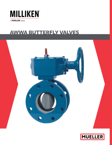
4. Maintenance & RepairCautions1. Before performing any maintenance or repairs, unplug your robot from power.2. B e sure no objects like dented balls, hair, string, etc. fall into the net and then work their way intothe machine where they can cause ball jams or interfere with correct operation.3. T able tennis robots work best with clean, worn balls. When adding new balls, please wash the grittymanufacturing powder off them first with warm, soapy water, then rinsing and drying before using.(Butterfly brand balls are pre-washed at the factory so this step is unnecessary with new Butterflyballs.) Keep your playing area clean to prevent balls that have rolled on the floor from picking up dirtand introducing that dirt into the machine.4. T he wheels have a special coating that prolongs their lifetime. Do not attempt to clean the wheelswith any chemical, as the chemical can be detrimental to the coating.5. A MICUS robots are designed for use in clean, dry, indoor rooms. Do not use outdoors or in any wetor damp environment. Avoid leaving your robot in a hot car or trunk.6. U se only 40 or 40 balls in your robot. The better ball you use (3-star are best), the more consistentyour robot can throw that ball.Checking & Adjusting Wheel ClearanceAMICUS wheels are very durable (at least 1000hours). But eventually, these wheels will weardown after long or intense use. As the wheelswear down, the space among the 3 wheelsenlarges, causing the wheels to lose their grip onthe ball. Dropping the robot or other similar trauma during transport or use can also cause this.One sign that the space among the wheels needsto be adjusted is that the machine releases theballs at irregular lengths at high speed. When thelength of the ball throws becomes irregular, thespace among the 3 wheels needs to be adjusted.To check the space among the wheels, placethe Wheel Adjustment Gauge (black tube with 3fins) in the space among the 3 wheels, fins endfirst, and so the fins do not touch any wheel (seePhoto 8A). Now move it in and out. If the distanceis correct, the gauge can be moved in and outeasily, but with the wheels just barely touchingthe outer surface of the gauge (wheels may turnslightly as the gauge is moved). If the wheelsdo not grip the gauge at all, or conversely, theyPhoto 8APhoto 8B13
tightly grip the gauge, then wheel adjustment iscalled for.Photo 8CTo adjust the wheels, push the gauge into theend of the Ball Tube where the ball comes out soit is held rigidly in place. Then use the 4 mm hexwrench found in the accessories to loosen thehex screw near the cover of the motor (see Photo8B). Now move the motor (gripping its cover)either towards or away from the gauge until thewheel barely touches it (see Photo 8C). Lastly,tighten the 4 mm hex screw to hold the wheel inplace. Do this with all 3 motors.Please note: The diameter of the adjusting tube is 35 mm, which is the ideal amount of space among the3 wheels. The robot functions correctly up to a diameter of 37-38 mm.Replacing The WheelsWhen the wheels can’t be adjusted anymore, or the special coating on the wheels has worn off, thewheels should be replaced. To do so, start with the lower wheel. Using the smaller 2 mm hex wrench,loosen the small setscrew that holds the wheel onto the shaft of the motor (see Photo 9A) Before taking it off, check and memorize the exact position of the wheel on the shaft of the motor. Pull the wheeloff the motor shaft and remove the three #1 Phillips screws that hold the foam wheel onto the hardplastic hub. Remove the wheel from the hub and replace with a new wheel. Then refasten the hub to thewheel. Slip the wheel assembly onto the motor shaft until the position of the original wheel is reached.Tighten the setscrew.Now manually spin the wheel to be sure it is not rubbing on any surface. If so, loosen the setscrewand slightly move
the Base. Pick up the robot, angle the Support Legs downward, slip them under the end of your table tennis table, and push the robot onto the end of the table. Gently let go of the base and the robot will hang by its own weight as seen in Photo 2. Please note that AMICUS