Transcription
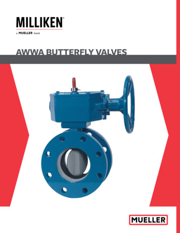
AWWA BUTTERFLY VALVES
TABLE OF CONTENTS3" THROUGH 20" BUTTERFLY VALVESScope of Line511A Flanged — 3" through 20".2510A Mechanical Joint — 4" through 20".2Design Details.3Features and Benefits — 20" and smaller .4Cv Values — 20" and smaller.4Suggested Specifications — 20" and smaller.5Dimensions511A Flanged — 3" through 20".6510A Mechanical Joint — 4" through 20".6Actuator Dimensional Data — 20" and smaller.7Optional Accessories.724" AND LARGER BUTTERFLY VALVESScope of Line511A Flanged — 24" through 72".8510A Mechanical Joint — 24" through 48".8Features and Benefits — 24" and larger.8Dimensions511 Flanged — 24" through 72".9510 Mechanical Joint — 24" through 48".9Suggested Specifications — 24" larger . 101
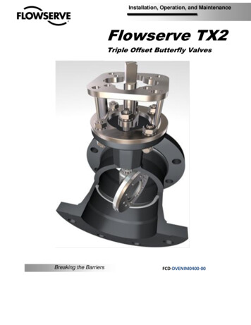
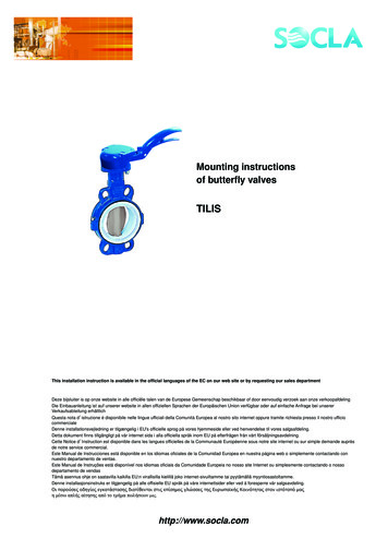
AWWA BUTTERFLY VALVESSCOPE OF THE LINE: AWWA RUBBER SEATED BUTTERFLY VALVESMODEL 511A FLANGED BUTTERFLY VALVESIZES3" through 20"BODY STYLEFlanged x flanged endsPRESSURE CLASSClass 150B per AWWA Standard C504WORKING PRESSURE150 psigFLANGESFlat faced and drilled in accordance with ANSI B16.1, Class 125 standardsRUBBER SEATBonded seat-in-bodyMODEL 511A BUTTERFLY VALVEACTUATION OPTIONS MDT manual actuator with AWWA nut, handwheel or chainwheel Hydraulic or pneumatic cylinder Electric actuatorMODEL 510A MECHANICAL JOINT BUTTERFLY VALVESIZES4" through 20"BODY STYLEMJ x MJ endsPRESSURE CLASSClass 150B per AWWA Standard C504WORKING PRESSURE150 psigRUBBER SEATBonded seat-in-body extends over inner surface to form self-gasketing featureACTUATION OPTIONSMDT manual actuator with AWWA nutPlease see the outside back cover for a listing of other Milliken products2MODEL 510A BUTTERFLY VALVE
AWWA BUTTERFLY VALVESDesign Details: Models 511A and 510A — 20" and SmallerSELF ADJUSTING PERMANENT PACKINGChevron type packing increases sealing force as line pressureincreases. The self adjusting packing bears on turned, groundand polished stainless steel, minimizing wear and assuring longlife. Packing is accessible for replacement without dismantlingthe valve per AWWA Standard C504.LIFETIME BEARINGSChemically inert nylon bearings are sized to meet or exceedAWWA specification pressure loads. They are self-lubricating,require no periodic maintenance and are designed to outlastthe life of the pipe line.CORROSION RESISTANT SHAFTSShafts in rubber seated butterfly valves, 3" through 20", areconstructed of centerless, ground ASTM A276 type 304 ortype 316 stainless steel bar and thus are not susceptible tocorrosion as are carbon steel or other similar materials. Shaftsare one-piece, through-shaft construction, sized to meet orexceed the requirements of AWWA Standard C504 for Class150B butterfly valves.STREAMLINED DISCSThe lens-shaped discs are designed to minimize pressure dropand turbulence. In the full open position, the disc creates nomore friction loss than a 45 elbow. Discs are secured to shaftsby stainless steel pins to transmit required torques and withstand stresses imposed under a variety of operating conditions.BODY SEATOur standard seats are constructed of Buna N rubber andbonded to the valve body. This molding process ensures thatthe disc-to-seat interference will not cause excessive wear orabrasion under normal operating conditions. The seat-in-bodydesign minimizes the effects of corrosive build up on the insideof the valve because deposits are swept away by the hardsealing edge of the disc each time the valve is exercised.HEAVY DUTY BODIESBoth Models 511A and 510A bodies are heavy duty cast iron.Model 511A flanges are fully faced and drilled in accordancewith ANSI B16.1, Class 125 standard for cast iron flanges.Model 510A mechanical joint end connections are in accordancewith AWWA C111 and ANSI 21.11. The actuator mountingtrunnion is machined and drilled for a 4-bolt connection.3
AWWA BUTTERFLY VALVESFeatures and Benefits of Milliken Models 511A and 510A — 20" and SmallerFEATUREBENEFIT Seat-in-body design Seat molded in recessed body cavity, protected bymetal on 3 sides Valve withstood proof-of-design testing of 100,000cycles - AWWA only requires 10,000 cycle proof-ofdesign testingReduces seat failure due to corrosive buildup inthe valve and pipeline. No hard ware to loosen. Noperiodic maintenance required. Rubber protectedfrom flow media to increase seat life. Proven reliability over the life of the valve Provides a tight disc-to-shaft pin connection, greatlyreducing the possibility of loosening through vibration Higher Cv: lower head loss results in energy savings forcustomer’s system Prevents galvanic corrosion and provides lowercoefficient of friction Self-adjusting, lasts the life of the valve Through-disc pinning Symmetrical lens-shaped disc Nonmetallic bearings Chevron V-type packingTYPE OF MATERIALVALVE SIZECVVALVE SIZECV3"32310 "44584"57512"64206"129414"873820 "8"2300VALVE SIZECVVALVE SIZEBODY16"114133 " - 4"Ductile IronCF-8MType 304SS18 "144446"Cast IronCF-8MType 304SS178328 " - 20 "Cast IronCast Iron /316SS EdgeType 304SSC V values for the 511A and 510A in thefull open positionDISCSHAFTOther materials available upon request4
AWWA BUTTERFLY VALVESSuggested Specification for the Milliken Rubber Seated Butterfly Valve, Sizes 3" through 20"GENERALPAINTINGButterfly valves shall be manufactured in accordance with the latestrevision of AWWA C504, Class 150B and conform to NSF Standard 61.The manufacturer shall have produced AWWA butterfly valves for aminimum of five years. All valves shall be either 511A Flanged or 510AMechanical Joint and comply with the following details.All surfaces of the valve interior shall be clean, dry and free fromgrease before painting. The valve interior and exterior, exceptfor disc edge, rubber seat and finished portions shall be evenlycoated with a 2-part liquid epoxy to comply with NSF61 and AWWAStandard C504.VALVE BODIESTESTINGValve bodies shall be constructed of ASTM A126, Class B cast iron.Flanged valves shall be fully faced and drilled in accordance withANSI Standard B16.1, Class 125. Mechanical joint end connectionsare in accordance with AWWA C111 and ANSI 21.11.PROOF OF DESIGNVALVE SEATSRubber body seats shall be of one piece construction,simultaneously molded and bonded into a recessed cavity in thevalve body. Seats may not be located on the disc or be retained bysegments and/or screws.VALVE BEARINGSValve bearings shall be of a self-lubricating, non-metallic materialto effectively isolate the disc-shaft assembly from the valve body.Metal-to-metal thrust bearings in the flow stream are not allowed.VALVE DISCThe disc shall be a lens-shaped design to afford minimal pressuredrop and line turbulence. Materials of construction shall be: 3" - 6" — ASTM A351 Gr. CF8M stainless steel disc 8" - 20" — ASTM A126, Class B cast iron disc with a stainlesssteel type 316 edgeDiscs shall be retained by stainless steel pins which extendsthrough the full diameter of the shaft to withstand the specifiedline pressure up to valve rating and the torque required to operatethe valve. Disc stops located in the flow stream are not allowed.VALVE DISCValve shafts shall be of stainless steel type 304. At the operatorend of the valve shaft, a packing gland utilizing “V” type chevronpacking shall be utilized.5Hydrostatic and seat leakage tests shall be conducted in strictaccordance with AWWA Standard C504.The manufacturer furnishing valves under the specification shall beprepared to provide Proof of Design Test reports to illustrate that thevalves supplied meet the design requirements of AWWA C504.MANUAL ACTUATORSManual actuators shall be of the traveling nut, self-locking type andshall be designed to hold the valve in any intermediate positionbetween fully open and fully closed without creeping or fluttering.Actuators shall be equipped with mechanical stop-limiting devicesto prevent overtravel of the disc in the open and closed positions.Actuators shall be fully enclosed and designed to produce thespecified torque with a maximum pull of 80 lb. on the handwheelor chain wheel. Actuator components shall with stand an inputtorque of 450 lb. ft. at extreme operator position without damage.Manual actuators shall conform to AWWA C504 and shall beMilliken MDT or an approved equal.
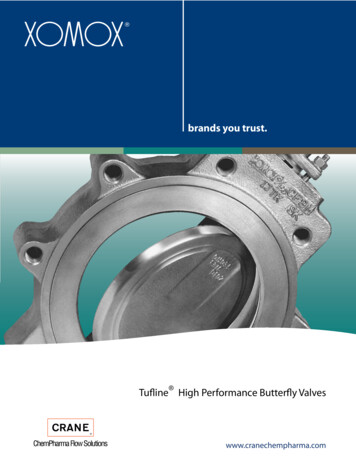
AWWA BUTTERFLY VALVESDimensional DataMODEL 511A, FLANGED BUTTERFLY VALVE 3" - 20"F Number and Size of Bolts125 lbs. Standard Layout.ANOMINAL VALVEAll Holes are 1/8" LargerThan Bolt Diameter Exceptas Noted.BSIZEABCDEFG34-3/43-7/87-1/253/44 - 5/8645-1/24-1/8951-5/168 - 5/87-1/266-1/25-1/811518 - 3/49-1/287-3/46-1/213-1/261-1/88 - 3/411-3/4910NominalValve Size9-7/81681-3/1612 - 7/814-1/410-1/2 11-3/81981-1/412 - 7/8171411-7/8 12-3/42181-3/812 - 118-3/41613-1/2 14-3/8 23-1/281-7/1616 - 121-1/41814-3/8 15-1/481-9/1616 - 1-1/8 22-3/481-11/1620 - 1-1/8124 Tapped Holes - N.C. (2) R.H. X E DeepEach Face on Valve 18" & Larger. StraddleCenter Line.G Bolt CircleC Flange OD20E162516-7/8 27-1/225All dimensions shown in inches.Available in Sizes 3" Through 20"DEMODEL 510A, MECHANICAL JOINT BUTTERFLY VALVE — 4" - 20"F No. & Size of BoltsNOMINAL VALVEG BoltCircleNom.CValveSizeRE EDX Laying LengthAPipeO.D.PipeI.D.Installation DiagramNote: The following items to be furnishedby others unless otherwise specified incontract: Bolts, Glands, Nuts, GasketsSIZEAB45-1/23-1/298-1/814 - 3/47-1/23-1/866-1/25-1/8118-1/211/166 - 3/49-1/23-1/287-3/46-1/213-1/48-5/81-1/86 - 3/411-3/43-5/81099-3/415-9/169-1/413/168 - 3/4144-1/410-1/2 11-3/8 17-15/169-1/41-1/48 - 3/416-1/44-1/41411-7/8 12-3/420-5/1611-1/215/1610 - 3/418-3/44-1/21613-1/2 14-1/222-9/16121-3/812-3/421514-3/8 15-3/8 24-11/16 12BSee Note 1PIPE SIZEPIPE O.D.PIPE 21.6018.961617C27-3/32D12-1/2EFAll dimensions shown in inches.Mechanical joint end is in compliance with ANSI 21.11.Available in sizes 4" through 20"6GX
AWWA BUTTERFLY VALVESActuator Dimensional Data for Models 511A and 510A — 20" and SmallerMDT MANUAL ACTUATORQAll dimensionsshown in inchesSPJNLTRV Dia.MW Dia.ChainwheelHandwheelVALVE SIZEMDT SIZEJLMNP3" to 12"MDT-24-11/16214", 16"MDT-35-5/82-7/162-1/824-1/218", 20"MDT-46-3/822-7/32 3-3/83-1/4 3-5/32 5-3/84QRST4-1/48-1/47-7/87-7/8VW# OF TURNSTO CLOSE8 9-1/8325-3/8 10-3/8 10-1/2 10-1/8 12 9-1/8307-5/16 6-3/4 11-5/16 11-1/21112 9-1/840OPTIONAL ACCESSORIESWe offer a variety of actuator extensions to meet our customer’srequirements. The choice of extension style is determined by the needfor valve position indication, location of the actuator and application.EXTENSION STEM WITH AWWA NUTPneumatic, electric and hydraulic operation isavailable, complete with limit switches and solenoidvalves when required.Factory fitted locking devices are available for wrench operatedand gear operated valves.The valve may be ordered with the plug positions pre-set at thefactory to suit the port flow requirements. This is achieved byfitting a styling ring to the valve stem.EXTENSION BONNETGear operators are available for all sizes. They can be providedwith 90 , 180 or 270 travel and are fitted with travel stops. 360 travel is also available.EXTERNAL PACKING BONNETEXTENSION BONNETEXTENSION STEM WITH2" AWWA NUTINDICATING HANDWHEEL FLOORSTAND, TORQUE TUBE FLOORSTAND,MOTOR ACTUATOR ON FLOORSTANDSTEM GUIDETo provide 90 flow paths only, a double-style plug is availablewhich operates through 90 travel and isolates either straightthrough port (Style A90 only).INDICATING HANDWHEELFLOORSTANDTORQUE TUBEFLOORSTANDMOTOR ACTUATORFLOORSTANDSTEADYBEARINGCoupling1"Support BracketWhen RequiredUniversalJointUniversalJointTorque Tube and ExtensionBonnet Lengths to beDetermined by CustomerUniversalJointShown in aValve Box7**To beDeterminedby CustomerWhen WallBracket isRequired.
AWWA BUTTERFLY VALVESMILLIKEN MODEL 511 FLANGED / 510 MECHANICAL JOINTSIZES24" through 72"BODY STYLE Flanged (24" - 72") Mechanical Joint (24" - 48")PRESSURE CLASSClass 150B per AWWA Standard C504ACTUATION OPTIONS Handwheel Electric Motor Pneumatic or Hydraulic Cylinder Buried Service ChainwheelMATERIALS OF CONSTRUCTION Body – ASTM A126 CLB cast iron Disc – ASTM A536 Ductile Iron Disc Edge – ASTM A276 Type 316 stainless steel Seat – Buna N/EPDM rubber retained in the body Seat Segments – ASTM A276 Type 316 stainless steel Shaft – ASTM A276 Type 304 stainless steel Bearings – Teflon lined fiberglass backed Packing – Buna N/EPDM – V type packing Paint – Liquid epoxy conforming to NSF 61 (lined and coated) No special tools or training required to adjust and/orreplace the seatFEATURES AND BENEFITS Rubber seat in body Recessed segmented seat retention Mechanically adjustable seat Epoxy paint Reduces potential corrosion and extends valve life Flow though disc design Reduces the chance of seat damage from tuberculation orother solidsDisc design results in lower head-loss than solid or hollowdisc designs Allows for simple bi-directional point adjustment on rubberseat while keeping hardware out of flowstream8
AWWA BUTTERFLY VALVESFIGURE 511: 24" - 72" CLASS 150 B FLANGED ENDSFlanged EndVALVE -7/8 32-11/164834-1/16 36-7/8CDEF3281-7/8G20 - 1-1/4 29-1/238-3/4 12 2-1/8 28 - 1-1/4364612 2-3/8 32 - 1-1/2 42-3/45312 2-5/8 36 - 1-1/2 49-1/259-1/2 15 2-3/4 44 - 1-1/25437-1/2 40-11/16 66-1/4 1541-3/4 45-3/167315 3-1/8 52 - 1-3/4 69-1/46646-1/16 45-3/167315 3-1/8 52 - 1-3/45053-1/8356607244 - 1-1/2 62-3/47686-1/2 18 3-1/2 60 - 1-3/4 82-1/2*Contact us for larger sizesENominal Valve SizeBDG Bolt CircleC Flange ODNote: Tapped Holes: "F" Size UNC-2B X "E" Deep24" Valve 4 Holes 2 Top & 2 Bottom30" & Up 8 Holes 4 Top & 4 BottomEach FlangeFIGURE 510: 24" - 48" CLASS 150 B MECHANICAL JOINTMechanical JointAVALVE SIZEABENominal Valve SizeG Bolt CircleDX LayingLengthCF No. and Size of BoltsInstallation DiagramDESIGN DETAIL9D31-9/16 24-1/839201-13/1620 - 136-7/8103625-7/162845-7/822224 - 143-3/4144229-7/8335322228 - 1-1/4 50-5/8144834-1/16 36-7/859-7/824232 - 1-1/4 57-1/216*Contact us for larger sizesBC
AWWA BUTTERFLY VALVESSuggested Specifications (24" and Larger)GENERALPACKINGAll butterfly valves shall be of the tight closing, rubber seat typeconforming to the design standards of ANSI / AWWA C504 latestrevision. Valves shall be bubble-tight at the rated pressure in eitherdirection and shall be suitable for throttling service and/or operationafter long periods of inactivity. Manufacturer shall have a minimum offive (5) years experience producing AWWA butterfly valves.On valves 24" and larger the packing will be V-type. All packingwill be self adjusting and wear compensating. Valve packingarrangement shall be designed so that actuator removal will notresult in packing seal failure.BODYAll valve bodies shall be constructed of ASTM A126 Class B cast iron.Flanged valves shall have ANSI B16.1 flanges with class 125# drilling.Mechanical Joint Valves shall have ends conforming to the ANSI /AWWA C111 / A21.11 standard.SEATOn 24" and larger valves the seat shall be adjustable and replaceable inthe field without the use of special tools. Valve seats on valves 24" andlarger will be designed for bi-directional adjustment without removal ofthe seat. Valve designs with the rubber seat on the disc are not acceptable.PAINTValves 24" and larger will be lined and coated with a liquid epoxyconforming to AWWA C550 and NSF61. Coatings will be a minimumof 8 mils DFT.TESTINGAll valves shall be hydrostatic and leak tested in accordance withANSI / AWWA C504.MANUAL ACTUATORSThe discs shall be constructed of ASTM A536 Ductile Iron with a 316stainless steel edge. 24" and larger discs will be the flow through design.Manual actuators shall be AWWA approved worm gear actuators.The actuator incorporates a hardened worm with bronze heavyduty quadrant within a ductile iron housing. Gear must beself locking type and shall be designed to hold the valve in anyintermediate position between fully open and fully closed withoutcreeping or fluttering. Worm gear to be rated 450 foot pounds atthe stops.SHAFTValves shall be Milliken model 511 / 510 or approved equivalent.DISCThe valve shaft shall be constructed of stainless steel ASTM A276 type304. On valves 24" and larger, a taper pin of 316 stainless steel will beused as the disc / shaft connection.BEARINGSAll shaft bearing shall be of the self-lubrication, corrosion-resistantsleeve type. Bearings shall be designed for horizontal and/orvertical shaft loading.10
MILLIKEN Product GuideSERIES 600 / 601EccentricPlug ValveFlanged and MJ Welded Nickel SeatStainless Ste
Suggested Specification for the Milliken Rubber Seated Butterfly Valve, Sizes 3" through 20" Dimensional Data MODEL 511A, FLANGED BUTTERFLY VALVE 3" - 20" MODEL 510A, MECHANICAL JOINT BUTTERFLY VALVE — 4" - 20" A Nominal Valve Size F Number and Size of Bolts 125 lbs. Standard Layout. All