Transcription
AMICUSEXPERTTable Tennis RobotOwner’s Manual Bedienungsanleitung Manuel d’utilisation1
AMICUS EXPERT Table Tennis Robot State of the art 3-wheel ball delivery technology provides all types of spin.Rigid sponge wheels with a special coating for longer durability.Compact, solid, functional construction with integral in encompassing ball collection net.Lightweight and easily transportable. Weighs only approximately 6 kg (13 lbs.). User-friendly Control Panel permits quick overall view with easy-to-understand adjustments.Random features include natural scattering of shots, random placement, or both!Programmed or random delivery of balls with different spin, speed, direction, and trajectory.Start Exercise with serve, which inserts natural pause before each repetition. 99 memory places, including 21 pre-programmed Exercises from Butterfly coach Richard Prause.Can be found on memory places 79-99AFC (Automatic Ball Frequency) function for more natural timing of balls in an Exercise.Alternate play and break periods (interval training) with the Cycle function.Adjust height of ball delivery to simulate anything from low serves to high lobs.Regulate all functions with the Control Panel located on the player’s end of the table.Covered by a full 2-year Manufacturer’s Warranty and a 5-year guarantee of parts and service availability. See full warranty information on page 26.CAUTIONS Please read this Owner’s Manual carefully before using the machine!This machine may only be connected to 100-230V current!The ball throw wheels rotate at high speed. Avoid touching the wheels during operation!Use this product only in enclosed and dry rooms!Used properly, your AMICUS EXPERT will always be a great training partner and a friend(AMICUS is Latin for Friend).2
IMPORTANT: Please read instructions carefully prior to use!The Control Panel chapter describes basic adjustments of the AMICUS EXPERT table tennis robot.More detailed instructions can be found in the Operation chapter.Contents1. Setup . 42. Control Panel. 63. Operation. 8Nomenclature. 8Adjustment Of Head Height. 8Starting Your Robot. 8One Ball Type Thrown To One Placement. 9One Ball Type Thrown To 2 Or More Placements. 10Throwing Different Ball Types In An Exercise. 10Changing Ball Settings in An Exercise. 11Random Controls. 11AFC Function (Automatic Frequency Control).12Memory Mode.12Saving An Exercise and Clearing a Memory Position.13Selecting, Playing, Changing and Moving Saved Exercises.13Pre-saved exercises.14Cycle Function.15Calibration.16The Remote Switch.17Linking The Remote To The Control Panel.17Changing The Battery In Your Remote. 18Take Down, Storage, & Transport. 184. Maintenance & Repair.19Cautions.19Checking & Adjusting Wheel Clearance.19Replacing The Wheels.20Ball Jams.21Other Maintenance. 225. Troubleshooting. 226. List of Replacement Parts. 247. Technical Data. 268. Warranty Information. 263
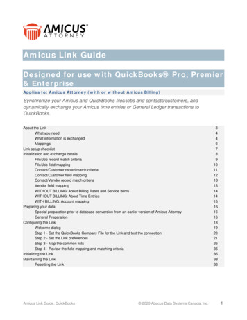
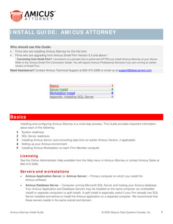
1. Setupa.b.c.d.e.Photo 1ARobot and Net AssemblyPower Supply (Input: 100-240V, Output: 24V DC, 3A)Control PanelControl Panel CableControl Panel BracketOther parts: Hex wrenches (2 and 4 mm) for wheels, Wheel Adjustment Gauge (black tube with fins), spare rub-ber bands for the SideNets, Velcro strips. White, steel strips to repair of the deflectorplate.1. P lace the robot on top of your table tennis table. Fold apartboth sides of the net at the same time until the first stop (Photo1A). Rotate towards you the curved tubular Support Legs intothe position as seen in Photo 1b (about 15–20 cm, or 6-8 in.,apart).Photo 1B2. R otate the entire robot 180 with the Support Legs facing awayfrom you. From behind, grasp the robot with both hands on thebottom of the Base. Pick up the robot, angle the Support Legsdownward, slip them under the end of your table tennis table,and push the robot onto the end of the table. Gently let go ofthe base and the robot will hang by its own weight as seen inPhoto 2.Please note that AMICUS robots are designed to fit onto 25 mm(1 in.) thick tops. If your top is less than 25 mm thick, you willneed to adjust the Support Legs using the height adjustingscrews. Turn the screws inward until the thickness differencebetween 25 mm and your particular table surface is sufficientlyequalized.CAUTION: Please use the included longest Velcro strip to helpsecure the robot to the end of the table. This is especially important if children play around the table. The Velcro strip helpsstabilize the robot to prevent it being knocked off the table.3. L oosen the large Black Knob found on the rear of the Ball Tube.Rotate the head 180 and then pull the head upwards until the3rd coloured ring on the tube is just visible (Photo 3A), thentighten the Black Knob to hold it in place (but not too tightly).Lastly, fasten the Head Cable coming from the head to the serialconnector found on top of the Base (Photo 3B).4Photo 2
Photo 3APhoto 3B4. S tanding behind the robot, grip the top points of the net and fold the net down on both sides untilthe net fully opens (as seen in Photo 4A). Fit the plastic Corner Brackets of the net around thecorners of your table as seen in Photo 4B.Photo 4APhoto 4BNOTE: You may attach the two shortest Velcro strips to the corners of your table underneath theCorner Brackets to help the brackets stay down and stabilize the entire net.5. P ull a Side Net along the side line of the table and pass its thick rubber band over the top of thetable’s net standard (see Photo 5A). Then loop the rubber band around the Clamp Screw that holdsthe net onto the table. Attach the Side Net’s Velcro tab to its matching piece located on the CornerBracket as seen in Photo 5B.Photo 5APhoto 5B6. Plug your Power Supply into a power outlet and then into the power jack on the side of the Base.5
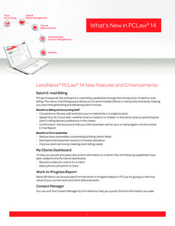
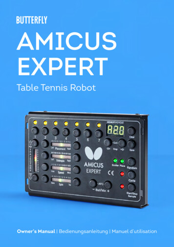
Connect the Control Panel Cable into the jack plug (looks like a headphone jack) on the side of theBase (see Photo 6A). Pull the Control Panel Cable to the opposite side of the table and connect it tothe Control Panel (see Photo 6B). Next attach the Control Panel Bracket on the side of the table andthen hang the Control Panel on the bracket. You may use a Velcro strip to help secure the bracketonto the side of the table. Before beginning to play on your robot, remove the rubber bands and bluefoam pad used on the head to help protect the Deflector Plate during shipment.Photo 6APhoto 6B2. Control 4121Clear1134-5 -4 -3 -2 -1 0 1 2 3 4 5LeftPlacementRight9075 604530 0 30456075 90LeftSidespinRight1 3 5 7 9 11 13 15 17 19 21LessSpeedMore-4 -3 -2 -1 0 1 2 3 4 5 6BackSpinTop567186Quit19Step817Scatter Place1020SaveEXPERTRandom16Cycle1213AFC14–Ball /Min 15Start/StopSample all LEDs (1–7) — When lit and solid, indicates a Ball is programmed for that spot. A flashingBlight Current Ball. Only selected balls can be changed. Number of lit LEDs indicates the number of balls in your Exercise.2 Ball Buttons (1–7) — When pressed, selects that ball. Once selected, all settings shown on6
panel apply only to the selected ball. Up to 7 balls may be added to an exercise. To delete a ball,press and hold the desired Ball Button until light goes out. To delete all balls at once, press andhold the 1 and 7 buttons until lights go out (except #1).3 4 Trajectory Buttons — Raise or lower the trajectory of the Current Ball. Pushing at the sametime, the robot will step into calibration mode.5 6 Placement Buttons — Shift the Current Ball placement to the left or right. Pushing at the sametime, the deflector plate position will reset.7 8 Sidespin Buttons — Shift the orientation of the sidespin to the left or right.9 10Speed Buttons — Decrease or increase the speed of the Current Ball.11 12Spin Buttons — Decrease or increase the amount of backspin or topspin.13 14 Ball/Min Buttons — Decrease or increase ball frequency (Ball/Min). Frequency rate is shownon the Display (22) from 1 to 100. Press briefly to change numbers one by one, or hold downto change numbers quickly. Pressing both buttons at the same time activates AFC (AutomaticFrequency Control) and AFC is shown on the display.15 Start/Stop & Sample Button — Press briefly to start or stop ball delivery. Hold down to throwsamples of Current Ball until released.16 Cycle Button — Press briefly to activate the Cycle function. Press for 2 seconds to programthe Cycle function. See page 15 for more details.17 Random Button — Press once to select Random Scatter, press a second time to select Random Place, and press a third time to select Random Scatter Place. Press a 4th time to exit.18 19 Step Buttons — Use to enter Memory Mode and select the Memory Position (E01–99). Pressingboth at the same time exits Memory Mode. Also used for programming the Cycle function (seepage 15).20 Save Button — Saves an Exercise into memory in the position shown on the Display (22). Anempty memory position (indicated by a flashing E ) must be selected using buttons 18 & 19.Hold down the Save button until E stops flashing.21 Clear Button — Clears a Memory Position. A saved Exercise must be shown on the display (solidE ). Hold down the Clear button until the display starts flashing.22 Display — Shows various information (see 9, 10, 12, 13, 15, 16, 17, 21).Also shows error codes (Er ).7
3. OperationNomenclatureTo assist in clearly communicating the various features of your robot, it is necessary to define how werefer to certain elements. Here are various terms used throughout this manual:Ball Type — 4 controls affect Ball Type: Spin, Speed, Sidespin, and Trajectory.Ball Placement — the left/right location where a ball lands, determined by the Placement control.Basic Ball — the ball that is thrown when the Control Panel is first powered on and no adjustmentshave been made. This ball will have no spin with medium speed and height. All Ball Type and Placementindicators on the Control Panel should be green (Trajectory will be green & red).Current Ball — the ball that is currently selected as indicated by its flashing Ball LED.Ball 1–7 — refers to the Ball Buttons and corresponding Ball LEDs.Exercise — a sequence of between 1 and 7 shots. Also called drill, program, or rally.1–4 Rings — how the head height adjustment is described. E.g., 3 Rings would mean the head height isadjusted so 3 rings (painted on the Ball Tube) are visible (see Photo 7).Adjustment Of Head HeightOn most table tennis robots, the height of thehead cannot be adjusted. In contrast, AMICUSEXPERT offers 4 different heights to better simulate realistic play. It is quite easy to adjust thehead height. From be hind the net, push the topof the net down to reach over it. Grab the curvedball tube with one hand and loosen the largeBlack Knob with the other hand (see Photo 7).You can then pull the tube up or push it down toadjust head height. Lock it in place by tighteningthe Black Knob. (Be careful not to tighten theknob too much.)Photo 7IMPORTANT: Before tightening the Black Knob, be sure one of the coloured rings painted on the balltube is right at the top of the lower tube (see Photo 7). Be careful not to tighten the Black Knob tootightly—you can dent the tube if tightened too much. Failure to adjust the head height correctly canresult in ball jams, double throws, missed throws, and other feed issues.Starting Your RobotAfter completing Step 6 on page 5, place about 50 or more 40 or 40 balls into the net trays. TheBall 1 LED should be flashing yellow and the Start/Stop LED should be solid red on your Control Panel.8
Press Start (you will hear the wheels start spinning) and balls will begin loading into the machine. Aftera few seconds, the first ball will reach the top of the Ball Tube. Press Stop to halt ball feed.Grab your racket and prepare to return balls from your robot. The first balls that are thrown will beBasic Balls and should be delivered along the centerline. Press Start and observe where the balls landin relation to the centerline. If balls are delivered either left or right of the centerline, then stop balldelivery. At the robot, loosen the large Black Knob on the rear of the Ball Tube (see Photo 7) and rotatethe head in the direction necessary for balls to land closer to the centerline. Repeat until all balls arelanding close to the centerline, then press Stop.One Ball Type Thrown To One PlacementThe easiest way to learn the various controls is to start with a single ball type delivered to one location.Please remember that only the Current Ball (indicated by a flashing Ball LED) can be changed. Uponpowering on the Control Panel, only the Ball 1 LED should be lit and it should be flashing. If any otherBall LED is lit, hold down its corresponding Ball Button until its LED becomes unlit.To adjust Ball Type: T he Trajectory Buttons raise (3) or lower (4) the ball trajectory (throw angle). One short push changes 1 unit (about 0.5 ) of the throw angle (fine adjustment). Each Trajectory LED represents 7 unitsof adjustment if a single LED is lit and 9 units if 2 LEDs are lit. The exceptions are the 5 and –5 LEDs,which represent 16 and 8 units respectively. Altogether there are 154 units of Trajectory adjustment.If you hold down a Trajectory Button, the stepping action is accelerated and you rapidly change thesetting. T he Sidespin Buttons (7 & 8) change the orientation of the sidespin on the ball. The zero settingmeans there is no sidespin on the ball. Each button press from zero represents a 15 change inorientation, except for the first press, which is 30 . Settings to the right of zero are degrees of rightsidespin and settings to the left are degrees of left sidespin. T he Speed Buttons reduce (9) or increase (10) the speed of the ball. There are 21 increments ofspeed adjustment. T he Spin Buttons reduce (11) or increase (12) the amount of spin on the ball. A setting of zero indicates no spin (dead ball). Settings to the right of zero (1 to 6) indicate stronger and stronger amountsof topspin. Settings to the left of zero (-1 to -4) indicate stronger and stronger amounts of backspin.To adjust Ball Placement (also called place or location): T he Placement Buttons (5 & 6) determine the left to right landing spot of the ball. The zero positioncorresponds with the centerline of the table. The 1 to 9 settings correspond with balls progressivelylanding closer and closer to the right corner of the table. The -1 to -9 settings correspond to ballslanding progressively closer and closer to the left corner.To adjust Ball Frequency: T he Ball/Min Buttons decrease (13) or increase (14) the rate, or frequency, of shots. When eitherbutton is pressed, the frequency, in balls per minute, is shown on the display. You can select settingsfrom 1 to 100 balls/min.9
Once you have adjusted the above settings to your liking, press the Start Button to have the robot deliver your chosen ball type to your chosen location at your desired frequency. If it is not what you want,press Stop and change the settings until you get the type of shot you want. Then try again. Althoughyou may find it easiest to stop play to make changes to the settings, when throwing only 1 ball, you canalso change settings on the fly, without stopping play.One Ball Type Thrown To 2 Or More PlacementsOnce you have the ball type selected as described in the preceding section, it is a simple matter to havethat same shot delivered to more than one place. To add additional Placements to your Exercise, pressthe Ball 2 button. Ball 2 LED will begin flashing, which indicates it is now the Current Ball (and Ball 1 LEDwill stop flashing to indicate it is no longer the Current Ball). Please notice that AMICUS has copiedover all settings from the current Ball to Ball 2. To select a different landing spot for Ball 2, all you haveto do is change the Placement setting.You can continue this same procedure to add up to 7 Balls to your Exercise. With each added Ball, youwill notice that the corresponding LED will light up. By looking at the number of Ball LEDs that are lit,you can quickly tell the number of shots in an Exercise.To play your Exercise, press Start, and AMICUS will throw the balls in order from 1 through howevermany Balls have lit LEDs. E.g., if you have 3 Balls with lit LEDs, AMICUS will throw Ball 1, followed by Ball2, and followed by Ball 3. Then it will start over with Ball 1. It will continue this order of thrown balls untilyou hit Stop.If you need to test an individual Ball in an Exercise, without the other Balls being thrown, you will usethe Sample function. To enable sampling, press and hold down the Start Button. It will begin throwingthe Current Ball (whichever one is flashing). Let go of the Start Button when you are finished sampling.Throwing Different Ball Types In An ExerciseWith AMICUS EXPERT, you can change the Ball Type, not just the Ball Placement, for each Ball in anExercise. For instance, you can design an Exercise that starts with a short backspin serve to the center,followed by a slow, medium high, heavy spin loop to the backhand, then a fast, powerful loop to theforehand, and ending with a high no-spin pop-up in the center.To design such an Exercise, just change the Spin (including Sidespin), Speed, and/or Trajectory for each ballin the Exercise. Be sure the Ball LED is flashing (indicating Current Ball) before changing any parameters ofthat Ball. And use the Sample button to test each Ball after you have changed any of the parameters.Best practices: Before starting to play such an Exercise, choose each Ball and look at all the Ball Typeand Ball Placement settings to get an idea of what type of shots will be delivered, to which locations,and in what order. Then check what the Ball Frequency is by pressing one of the Ball/Min Buttons andobserving the frequency rate on the display. For an Exercise like the one described above, with severalchanges of spin and speed, it is advisable to turn on AFC (explained next).If you want a certain Ball more than once in an Exercise, set that Ball first, as its settings will be copiedover to the new Ball that you select. You can even copy Balls out of order. For instance, If Ball 2 willalso be used as Ball 4, after setting Ball 2, and with Ball 2 LED flashing, press the Ball 4 Button and thesettings for Ball 2 will be copied over to Ball 4 (and Ball 4 LED will begin flashing).10
When using Random Place in an Exercise, the Placement will be randomly selected of the places whichhave been set in the exercises, but the Ball Type will remain in the same order as programmed.Changing Ball Settings in An ExerciseIf while playing an Exercise, you want to change the settings for a particular Ball, you can stop the Exercise by either pressing the button for the Ball you want to change or press the Stop Button. If you pressthe Ball Button, then that Ball will immediately become the Current Ball and you can begin changingthe settings immediately. If you use the Stop Button, then you will likely need to press the Ball Buttonfor the Ball you want to change before altering the settings. Use Sample to test your new settings.After you are satisfied with your changes, begin play again by pressing Start. At restart, the Exercise willalways resume at Ball 1.With AMICUS EXPERT, you can also change some settings while balls are being thrown. The advantageto doing this is that all balls in an Exercise will be changed simultaneously. The settings that can bechanged are Trajectory and Speed. You can also change Spin if all balls in the Exercise have the samespin. Changes during play are restricted to small increments in either direction (accelerated changesare not supported during play).As an example, let’s say you have 3 balls in an Exercise. Ball 1 is set at Speed 11 and Spin 1, Ball 2 atSpeed 12 and Spin 2, and Ball 3 at Speed 13 and Spin 3.During play, you decrease Speed downward by 1 increment and you increase Spin by one increment. Whathappens is that Ball 1 changes to Speed 10, Spin 2; Ball 2 to Speed 11, Spin 3; and Ball 3 to Speed 12, spin 4.You can also change Ball/Min during play without restriction (including acceleration).Random ControlsAMICUS EXPERT offers 3 types of randomization—Random Scatter, Random Place, andRandom Scatter Place. To activate, press theRandom Button. Your first press will selectRandom Scatter (the Scatter LED will light up).Press Random a second time and the Place LEDwill light up (and Scatter LED will darken). PressRandom a third time and both Scatter and PlaceLEDs will light up. Press a fourth time to turnRandom off (and both Scatter and Place LEDs willdarken).Random ScatterRandom Scatter is similar to the less precise shots that a human might deliver. Without RandomScatter, the robot typically delivers shots within an area approximately 13cm (5 in.) in diameter. But withRandom Scatter, balls are delivered in an enlarged area of approximately 40cm (16 in.) in diameter.Random Place requires at least 2 Balls in an Exercise. If there is only a single Ball, the Place LED will notlight up. The robot will then randomly select one of the Place ments programmed for the Exercise andthrow the ball there in an unpredictable order. E.g., let’s say an Exercise uses Placements of -4, 0, & 4.Without Random Place activated, the order of throws will always be -4, 0, 4, -4, 0, 4. But with Random11
Place on, the order could be something like 0, 4,4, -4, 0, 4,0, -4.Random PlaceRandom Scatter Place combines the above tworandom functions. The landing spots for everyBall are enlarged and Placements are randomized.Best practices: Do not program landing spotsthat are close to the side line, end line, or tablenet when using Random Scatter. If you do, manyballs are likely to be shot off the side or end of thetable or into the net because of the increased areaof the landing spots with Random Scatter. Whenusing Random Place, if you want throws deliveredto one spot more often than other spots, programmore Balls with the desired placement. E.g., if anExercise has 4 Balls with one of them using Placement 5 and three using Placement 0, then thereis a 1 in 4 chance a Ball will be delivered to 5, buta 3 in 4 chance a Ball will be delivered to 0. Lastly,while Random Place must have at least 2 Balls inthe Exercise, Random Scatter can be used withsingle ball Exercises.Random SCATTER PlaceAFC Function (Automatic Frequency Control)If you press and hold down both Ball/Min Buttonsat the same time for a couple of seconds, youactivate the AFC (Automatic Frequency Control)function. AFC will be shown on the display. AFC isuseful when you have changes in speed within anExercise. For example, when you start with a slow,short backspin serve followed by a fast topspinshot. Or you have several fast topspins followedby a slow, high pop-up. AFC can sense this changein speeds and automatically adjust the frequencyso the timing between shots is more similar to thetiming of those shots in a real game. Turn on AFC whenever you feel you don’t have enough time, or toomuch time, for one or two shots within an Exercise, but the rest of the shots seem OK. Deactivate AFCby once again pressing, and holding down for 2 seconds, both Ball/Min Buttons at the same time (AFCwill disappear from the display).Memory ModeThe Memory Controls (buttons 18–21) are used to save Exercises into memory, clear Exercises frommemory, and select Memory Positions of saved Exercises. After designing an Exercise, you will wantto save it in memory because as soon as you turn off power, your Exercise will be deleted unless it issaved. Also with 99 Memory Positions, you can design, and save, lots of different Exercises for different12
purposes, and have them readily available for easy recall.Once an Exercise is saved, each ball in that Exercise can be adjusted or deleted. And if an Exercise is nolonger needed, the entire Exercise can be deleted to open that Memory Position for a new Exercise.To enter Memory Mode, press one of the Step Buttons ( or ). If done during play, play stops. E01appears on the display to indicate you are in Memory Mode. The E stands for mEmory and the 01 is thenumber of the Memory Position. A flashing display indicates that Memory Position is open. WhateverExercise was showing before entering Memory Mode will now be showing in Memory Mode (provideddisplay is flashing). This allows you to now save that Exercise in that Memory Position.A solid (not flashing) display indicates an Exercise is saved in that position. In which case, lit Ball LEDsindicate each Ball of that Exercise. You can see the parameters of each ball by pressing on each BallButton and the settings for that Ball will be shown on the Control Panel.To exit Memory Mode, press both Step Buttons at the same time. Display will go blank to acknowledgeyou have left Memory Mode.Saving An Exercise and Clearing a Memory PositionTo save an Exercise, locate an open Memory Position (flashing E on the display) by using the StepButtons. Then hold down the Save Button 0) for 2 seconds. The display will stop flashing and becomesolid to indicate the Exercise has been saved into memory. Please note that only settings for Ball Placement and Ball Type are saved when the Exercise is saved. Settings for Ball/Min, Cycle, Random, and AFCare not saved.You cannot save an Exercise into an occupied Memory Position (solid E on the display). An occupiedMemory Position must first be cleared before it can be used to store a new Exercise. Before clearing aposition, please be positive that you no longer need th
bottom of the Base. Pick up the robot, angle the Support Legs downward, slip them under the end of your table tennis table, and push the robot onto the end of the table. Gently let go of the base and the robot will hang by its own weight as seen in Photo 2. Please note that AMICUS