Transcription
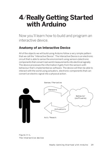
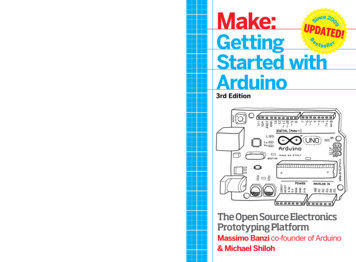
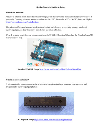
Getting Started with the ArduinoWhat is an Arduino?Arduino is a family of PC board-based-computing systems built around a microcontroller (microprocessor ifyou wish). Currently, the most popular Arduinos are the UNO, Leonardo, MEGA, NANO, Due, and LilyPad.https://www.arduino.cc/en/Main/ProductsThe primary differences between configurations include such features as operating voltage, number ofinput/output pins, on-board memory, form factor, and other subtleties.We will be using on of the most popular Arduinos' the UNO R3 (Revision 3) based on the Atmel ATmega328microprocessor chip.Arduino UNO R3 Image https://www.arduino.cc/en/Main/ArduinoBoardUnoWhat is a microcontroller?A microcontroller is computer on a single integrated circuit containing a processor core, memory, andprogrammable input/output peripherals.ATmega328 Image http://www.atmel.com/devices/atmega328.aspx
What is a computer?In it simplest form, a computer consists of Inputs, Processing, and Outputs.The processing system consists of Storage (Memory), Central Processing Unit (CPU) including a System ClockThe CPU general consists of a Control Unit and a Arithmetic Logic Unit.Computer Block DiagramComputer Block Diagram (Expanded)
What is a Central Processing Unit (CPU)?The processor core or Central Processing Unit (CPU) is the electronic circuitry that carries out the instructionsof a computer program by performing basic arithmetic including AND and OR, logical control (branching), andinput/output (I/O) operations. Internally the CPU has many different sub-components that perform each of theabove steps, and generally they can all happen independently of each other. This is analogous to a physicalproduction line, where there are many stations where each step has a particular task to perform. Once done itcan pass the results to the next station and take a new input to work on.Accordingly, principal components of a CPU includes the Arithmetic Logic Unit (ALU) that performsarithmetic and logic operations, Processor Registers that supply operands to the ALU and store the results ofALU operations, and a Control Unit (CU) that fetches instructions from memory and "executes" them bydirecting the coordinated operations of the ALU, registers and other components.Clock Speed, Cycles per Second, MIPS , FLOPSThe speed of the computer, given in Megahertz or Gigahertz (millions or thousands of millions cycles persecond). This is called the clock speed since it is the speed that an internal clock within the computer pulses.The pulses are used within the processor to keep it internally synchronized. On each tick or pulse anotheroperation can be started; think of the clock like the person beating the drum to keep the rower's oars in sync.MIPS Machine Instructions per SecondsFLOPS Floating Point Operations per SecondMachine InstructionsThe CPU executes instructions that are read from memory. There are two categories of instructions:1. Those that load values from memory into registers and store values from registers to memory.2. Those that operate on values stored in registers. For example adding, subtracting, multiplying, ordividing the values in two registers, performing bitwise operations (AND, OR, XOR, etc); or performingother mathematical operations (square root, sin, cos, tan, etc).BranchingApart from loading or storing, the other important operation of a CPU is branching. Internally, the CPU keeps arecord of the next instruction to be executed in the instruction pointer. Usually, the instruction pointer isincremented to point to the next instruction sequentially; the branch instruction will usually check if a specificregister is zero or if a flag is set and, if so, will modify the pointer to a different address. Thus the nextinstruction to execute will be from a different part of program; this is how loops and decision statements work.Control Unit (Fetch, Decode, Execute, Store)A single instruction consists of a particular cycle of events: fetching, decoding, executing and storing.For example, to do the add instruction the CPU must:Fetch - get the instruction from memory into the processor.Decode - internally decode what it has to do (in this case add).Execute - take the values from the registers, actually add them together.Store - store the result back into another register.
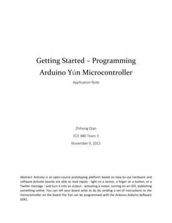
Comparing an Arduino to a ComputerComputerClockPower SupplyCentral Processing UnitArithmetic Logic UnitInputsKeyboardMouseOutputsControl UnitDisplayStorage (Memory)PrinterTouch PadPlotterTouch Screen3D PrinterMicrophoneAudio / VideoExternal Storage.External StorageArduino UNO R3Power Supply (Voltage Regulator), USB-UART, Clock (16 MHz), CPU (Atmel ATmega 328)ATmega328Memory: 32K Flash (Program), 2K RAM (Variables), 1K EEPROM (Data)Input/Output: 14 Digital & 6 Analog, Interrupts, USB, SPI, I2C, TWIInputs (Sensor Voltages):Audio, Light, IR, UV, PIR, Motion, Temperature, Humidity, Pressure, ChemicalOutputs:Relays, Actuators, Motors, Visual Displays (LEDs & LCDs), Audio, SD Chip, Data Logger
Arduino MicrocontrollerMemory SystemTimer SystemPort SystemSerial Communications SystemInterrupt SystemAnalog-to-Digital Converter (ADC)Arduino UNO R3ATmega328ATmega 328Memory System32K Programmable Flash2K RAM1K Addressable EEPROMPort System14 Digital I/O Pins6 Analog Input PinsTimer SystemTwo 8-bit TimersOne 16-bit TimerSix PWM ChannelsSerial CommunicationsSerial USARTSPITWIADC6 Channel 10-bitInterrupt System26 total Interrupts2 External Pin Interrupts
Interfacing with the Arduino
Getting Started with the Arduino (Input/Output Pin Configuration)Arduino UNO R3ATmega328ATmega 328Memory System32K Programmable Flash2K RAM1K Addressable EEPROMPort System14 Digital I/O Pins6 Analog Input PinsTimer SystemTwo 8-bit TimersOne 16-bit TimerSix PWM ChannelsSerial CommunicationsSerial USARTSPITWIADC6 Channel 10-bitInterrupt System26 total Interrupts2 External Pin InterruptsPower Supply (Voltage Regulator), USB-UART, Clock (16 MHz), CPU (Atmel ATmega 328)Atmel328Memory: 32K Flash (Program), 2K RAM (Variables), 1K EEPROM (Data)Input/Output: 14 Digital & 6 Analog, Interrupts, USB, SPI, I2C, TWIInputs (Sensor Voltages):Audio, Light, IR, UV, PIR, Motion, Temperature, Humidity, Pressure, ChemicalOutputs:Relays, Actuators, Motors, Visual Displays (LEDs & LCDs), Audio, SD Chip, Data Logger
Arduino Input and Output14 Digital I/O PinsEach of the 14 digital pins on the UNO can be used as an input or output, using pinMode( ), digitalWrite( ), anddigitalRead( ) functions. They operate at 5 volts. Each pin can provide or receive a maximum of 40 mA and hasan internal pull-up resistor (disconnected by default) of 20-50 kOhms.In addition, some pins have specialized functions:Serial: 0 (RX) and 1 (TX). Used to receive (RX) and transmit (TX) TTL serial data. These pins are connected tothe corresponding pins of the ATmega8U2 USB-to-TTL Serial chip.External Interrupts: 2 and 3. These pins can be configured to trigger an interrupt on a low value, a rising orfalling edge, or a change in value. See the attachInterrupt( ) function for details.PWM: 3, 5, 6, 9, 10, and 11. Provide 8-bit PWM output with the analogWrite( ) function.SPI: 10 (SS), 11 (MOSI), 12 (MISO), 13 (SCK). These pins support SPI communication using the SPI library.LED: 13. There is a built-in LED connected to digital pin 13. When the pin is HIGH value, the LED is on, whenthe pin is LOW, it's off.6 Analog I/O PinsThe UNO has 6 analog inputs, labeled A0 through A5, each of which provide 10 bits of resolution (i.e. 1024different values). By default they measure from ground to 5 volts, though is it possible to change the upper endof their range using the AREF pin and the analogReference( ) function.Additionally, some pins have specialized functionality:TWI: A4 or SDA pin and A5 or SCL pin. Support TWI communication using the Wire library.Power PinsThe power pins are as follows:Vin The input voltage to the Arduino board when it's using an external power source (as opposed to 5 voltsfrom the USB connection or other regulated power source). You can supply voltage through this pin, or, ifsupplying voltage via the power jack, access it through this pin.5V This pin outputs a regulated 5V from the regulator on the board. The board can be supplied with powereither from the DC power jack (7 - 12V), the USB connector (5V), or the Vin pin of the board (7-12V).Supplying voltage via the 5V or 3.3V pins bypasses the regulator.3.3V volt supply generated by the on-board regulator. Maximum current draw is 50 mA.GND Ground pins.IOREF. This pin on the Arduino board provides the voltage reference with which the microcontroller operates.A properly configured shield can read the IOREF pin voltage and select the appropriate power source or enablevoltage translators on the outputs for working with the 5V or 3.3V. AREF Reference voltage for the analoginputs. Used with analogReference( ).Reset Bring this line LOW to reset the microcontroller. Typically used to add a reset button to shields whichblock the one on the board.
Getting Started with the Arduino What is an Arduino? Arduino is a family of PC board-based-computing systems built around a microcontroller (microprocessor if you wish). Currently, the most popular Ardu