Transcription
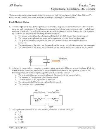
AP PhysicsPractice Test:Capacitance, Resistance, DC CircuitsThis test covers capacitance, electrical current, resistance, emf, electrical power, Ohm’s Law, Kirchhoff’sRules, and RC Circuits, with some problems requiring a knowledge of basic calculus.Part I. Multiple Choice1. Two metal plates of area A and separated by a distance d are placed in parallel near each other to form acapacitor with capacitance C. The plates are connected to a voltage source with potential V and allowedto charge completely. The voltage is then removed, and the plates moved so that they are now separatedby a distance 2d. Which of the following statements is true?a. The charge on the plates has changed, and the electric field between them has increased.b. The charge on the plates is the same, and the potential between them has decreased.c. The potential between the plates has increased, and the electric field between them hasdecreased.d. The capacitance of the plates has decreased, and the energy stored in the capacitor has increased.e. The capacitance of the plates has decreased, and the electric field between them has decreased.dielectric2. A battery is connected to a capacitor in order to set up a potential difference across the plates. While thebattery remains connected, a dielectric is inserted between the plates of the capacitor. Which of thefollowing statements concerning the capacitor with the dielectric is false?a. The potential difference across the plates of the capacitor is the same as before.b. The amount of charge on the plates has increased.c. The capacitance of the capacitor has increased.d. The net electric field between the plates has increased.e. The capacitor stores more energy.4Ω12Ω12Ω6Ω18V3. The equivalent resistance of the four resistors, connected as shown above, is:a. 7 Ωb. 4 Ωc. 2.7 Ωd. 8.5 Ωe. 14.4 Ω 2013, Richard Whitewww.crashwhite.com
AP PhysicsPractice Test:Capacitance, Resistance, DC Circuits1µF12V5µF6µF4. Three capacitors, of capacitance 1µF, 5µF, and 6µF, are arranged in a circuit with a switch and a 12-Vbattery as shown above. The equivalent capacitance of the three capacitors is:a. 2 µFb. 3 µFc. 6 µFd. 11/6 µFe. 11/12 µF5. Two conducting wires, W1 and W2, are made of two different materials, the first with a resistivity of ρ 1,ρthe second with resistivity ρ 2 1 . Which of the following pairs of cylindrical wires, with indicated2cross sectional area and length, will have equal resistances?Wire W1Wire W2a.2Ab.Ac.2ALA2Ld.AL2A2Le.A L2L2LAL2ALAL6. A capacitor is fully charged by a 10-Volt battery, and has 20 milliJoules of energy stored in it. The chargeon each conducting plate of the capacitor is:a. 2 10 3 Coulombsb. 4 10 3 Coulombsc. 2 10 4 Coulombsd. 4 10 2 Coulombs e. 2 10 2 Coulombs 2013,Richard Whitewww.crashwhite.com
AP PhysicsPractice Test:Capacitance, Resistance, DC Circuits6Ω4Ω3Ω18V7. Three resistances of 4Ω, 3Ω, and 6Ω are connected to an 18V battery as shown in the circuit above. Thepower dissipated by the 3Ω resistor is:a. 3Wb. 12Wc. 8Wd. 6We. 4W8. The cost of the electricity for running a 120-Volt computer for 10 hours is a little less than 25 cents. Ifelectricity costs 10 cents per kiloWatt-hour, what is the current running through the computer?a. About 2 Ab. About 4 Ac. About 1 Ad. About 3 Ae. About 0.3 ADimensions not to scale10 cmC15 cmC24 mm1 mm9. Capacitor C1 consists of square parallel plates 10-centimeters on a side, and separated by a distance of 4millimeters, as shown. Capacitor C2 has square parallel plates 5-centimeters on a side, and separated by adistance of 1 millimeter. What is the ratio between the capacitances of the two parallel-plate systems?a. C1:C2 8:1b. C1:C2 4:1c. C1:C2 2:1d. C1:C2 1:1e. C1:C2 1:2 2013, Richard Whitewww.crashwhite.com
AP PhysicsPractice Test:Capacitance, Resistance, DC CircuitsPart II. Free ResponseR1R2V10. Two resistors are placed in series with a battery of potential V as shown above.a. On the diagram, draw wires and a to show where you would connect a voltmetermeasure the potential across R1 . If any existing wires need to be disconnected inthe circuit, draw an X over those wires in the diagram.b. On the diagram, draw wires and a to show where you would connect an ammetermeasure the current traveling through R2 . If any existing wires need to bedisconnected in the circuit, draw an X over those wires in the diagram.VtoAtoResistance R2 has a value of 1.00 10 3 Ω . The voltmeter shows the potential across R1 to be 3.00V andthe ammeter shows the current to be 5.00 mA through R2.c. Calculate the value of R1.d. Calculate the power dissipated by R2.e. Calculate the terminal voltage V of the battery.f. The battery is disconnected from the circuit, and its potential measured to be 8.20 V. Determinethe internal resistance of the battery when it was connected in the circuit. 2013, Richard Whitewww.crashwhite.com
AP PhysicsPractice Test:Capacitance, Resistance, DC Circuits0.01 m0.50 m–q q0.50 m11. A parallel plate capacitor is created by placing two large square conducting plates of length and width0.50 meters facing each other, separated by a 1.00-centimeter gap. A source of potential is connected tothe two plates so that a charge of q σ A is placed on the left plate and a charge of q σ A is onthe right plate, where σ 500 10 6 C / m 2 . The potential source is then removed from the plates. Theplates are close together so electric field fringe effects at the edges are negligible.a. In the space below, draw electric field lines in the vicinity of the plates.–q 2013, Richard White qwww.crashwhite.com
AP PhysicsPractice Test:Capacitance, Resistance, DC Circuitsb. Use Gauss’s Law to determine the magnitude of the electric field between the plates.c. Calculate the electric potential V between the two plates.d. Calculate the capacitance of this capacitor. 2013, Richard Whitewww.crashwhite.com
AP PhysicsPractice Test:Capacitance, Resistance, DC CircuitsA dielectric of κ 2.00 is now inserted between the isolated plates while the same amount of charge Qremains on each plate.e. Calculate the new capacitance of the system with the dielectric between the plates.f. The electric field strength between the plates has (check one):increaseddecreasedremained the sameg. The electric potential between the plates has (check one):increaseddecreasedremained the sameh. The energy stored in the capacitor has (check one):increaseddecreasedremained the samei.How would your answers to f , g, and h change if the dielectric had been inserted while the voltagesupply was still connected to the capacitor? Explain. 2013, Richard Whitewww.crashwhite.com
AP PhysicsPractice Test:Capacitance, Resistance, DC Circuitsabc–Q Q12. A spherical capacitor is constructed of concentric conducting spheres. The interior sphere is solid, witha radius a and a charge of –Q. The exterior sphere is a hollow shell with inner radius b and outer radius c,and charge Q. Give symbolic answers as a function of the given variables and fundamental constants.a. Use Gauss’s Law to calculate the electric field E, magnitude and direction, for the space betweenthe spheres, where a r b.b. On the axes below, sketch a graph of electric field E as a function of r for the range 0 to 2c,where E 0 is away from the center. Eabcr–E 2013, Richard Whitewww.crashwhite.com
AP PhysicsPractice Test:Capacitance, Resistance, DC Circuitsc. Calculate the magnitude of the difference in electric potential V between the two spheres.d. Calculate the capacitance of this conducting-sphere system.e. The spheres are discharged, and then connected to a source of electric potential of magnitude2V. Calculate how much Work must be done to fully charge the capacitor under these newconditions. 2013, Richard Whitewww.crashwhite.com
AP PhysicsPractice Test:Capacitance, Resistance, DC CircuitsaR 2kΩC 2000µFV 12.0Vb13. The circuit shown above is constructed with a 12.0-Volt power supply, a 2.00 10 3 Ω resistor, and a2.00 10 3 F capacitor, initially uncharged. The switch is open, but then closed at time t 0.a. Calculate the time constant for the circuit.b. Calculate the initial flow of current, both magnitude and direction, when the switch is firstclosed.c. Write and solve a differential equation to find the charge Q on the plates of the capacitor as afunction of time t. 2013, Richard Whitewww.crashwhite.com
AP PhysicsPractice Test:Capacitance, Resistance, DC CircuitsaR 2kΩR 6kΩV 12.0VC 2000µFbThe switch is opened again, and a 6000Ω resistor placed across the circuit from point a to point b at anew time t 0.d. What is the time constant of this new circuit?e. At what time is the potential across the capacitor 6.00 V?f. Calculate the total energy dissipated by the 6000Ω resistor. (Assume that any heating effects ofthe wire are neglibigle.) 2013, Richard Whitewww.crashwhite.com
AP Physics Practice Test Solutions:Capacitance, Resistance, DC Circuits1. The correct answer is d. Once the plates are removed from the voltage source, they have a chargeQ CV . Moving the plates farther apart decreases their capacitance by a factor of 2 according toAC ε 0 . Although the capacitance of the system has changed, the amount of charge stored on thedplates has not: we conclude that the potential between the plates V must have increased as a result of theinverse relationship between C and V in Q CV . The electric field between the two plates is describedby the relationship V Ed , and because V and d have both increased by a factor of 2, we concludethat the electric field E between the plates is unchanged. The energy stored in the capacitor can be1calculated as a function of any two of Q, C, and V. In this case, UC QV reveals that, because V has2increased, the energy stored in the capacitor has increased as well. From a Conservation of Energyperspective, this extra energy arises as a result of the Work done in moving the two plates farther apart.The only answer consistent with the above analysis is d. 2. The correct answer is d. Inserting the dielectric into the capacitor increases the capacitance of theparallel plates. The battery maintains the potential across the plates V, so according to Q VC, we cansee that the amount of charge stored on the plates will increase. The electric field between the platesremains constant, however, based on V Ed. The capacitor, by virtue of its increased capacitance, stores1more energy, according to U CV 2 .23. The correct answer is a. Solve first for the pairs of resistors inparallel, then use those equivalent resistances to get the effective,or equivalent, resistance for the circuit as a whole.1 11 R1 R2 Requivalent4Ω12Ω12Ω6Ω18V1 11 Requivalent 3Ω4 12 Requivalent1 11 Requivalent 4Ω12 6 Requivalent4Ω3Ω18VNow use these two equivalent resistances in series to determinethe overall resistance.R1 R2 RequivalentRequivalent 3Ω 4Ω 7Ω 2013, Richard White7Ω18Vwww.crashwhite.com
AP PhysicsPractice Test Solutions:Capacitance, Resistance, DC Circuits4. The correct answer is b. The equivalent capacitance of the three capacitors can be found by calculatingthe 1µF and 5µF in parallel, and then putting the 6µF capacitor in series with that:C parallel C1 C5 C parallel 1µF 5µF 6µFNow we put the equivalent capacitance from the parallel capacitors in series with the remainingcapacitor:111 Cseries C parallel C61112 Cseries 6µF 6µF 6µFCseries 3µF ρL5. The correct answer is a. The resistance of a wire can be calculated using the formula R . With halfA as big a resistivity in wire W , wire W needs to either be half as long as W , or have twice as large a212cross-sectional area. Choice a satisfies this requirement.6. The correct answer is b. The charge stored in the plates of the capacitor can be determined using the1formula U QV :21U QV22U 2(20 10 3 J) Q 4 10 3 CoulombsV10V7. The correct answer is b. Analysis of the effective resistance of the resistor shows that the currentcoming from the battery is 3 Amps, resulting in a potential decrease of 12V over the 4Ω resistor. Thus, there is a 6V decrease over the 3Ω and 6Ω resistors.V 2 62The Power dissipated by that resistor can then be calculated using P 12W .R3A similar Power analysis may be performed by using P IV or P I 2 R , with appropriate valuessubstituted in. 8. The correct answer is a. Based on the total cost of the energy,the time, and the price per kWh, we can determine about how much Power the computer is using: 25cents kW hr1 0.25kW 250W110cents 10hrsNow, using P IV, we can determine the current being drawn by the computer:PP IV, so I V 250WI 2A120V 2013, Richard Whitewww.crashwhite.com
AP PhysicsPractice Test Solutions:Capacitance, Resistance, DC Circuitsε0 A,dwhere A is the surface area of the plates, and d is the separation between the plates. Here, C1 has 4 timesthe surface area of C2, but also 4 times the distance. This has the effect of giving the two sets of platesequal capacitance. εAC 0dC1 ε0 A1 /d1 C2 ε0 A2 /d29. The correct answer is d. The capacitance of a parallel-plate system can be determined using C 2C1 A1d2 (2x ) ( d ) 1 C2 A2 d1 ( x 2 )( 4d ) 110. a. The voltmeter mustbe placed over theresistor to measure thepotential differencebefore and after.VAb. The ammeter must be inserted intothe circuit so that there is only onepath for current to follow. Theammeter may be placed anywhere inthe circuit to measure current becauseit’s a series circuit and the current isthe same everywhere. But it make smost sense intuitively to place themeter near the resistor.1. The two resistors are in series, so the current I is the same throughout the circuit. Using Ohm’sLaw and the information we have for R1:V1 IR13V (0.005A)R13R1 600Ω0.0052. Using the stated current and resistance:P I 2RP (0.005A)2 (1000Ω) 2.5e 2W 25mW3. The terminal voltage of the battery can be calculated using the total I and R for the circuit, alongwith Ohm’s Law:V IRV (0.005A)(600Ω 1000Ω) 8.00V4. Terminal voltage is emf less the potential drop due to the internal resistance:V ε Ir8 8.2 (0.005)rr 40Ω 2013, Richard Whitewww.crashwhite.com
AP Physics11.Practice Test Solutions:Capacitance, Resistance, DC Circuitsa. With the plates in close proximity and negligible fringing:b. Gauss’s law can be used to determine the electric field for one plate,and then that effect can be doubled to account for the other plate,or Gauss’s law can be used with the two plates as arranged. Here, I’m drawing aGaussian surface that has field lines from the positively-charged plate goingthrough one surface of area A.q E dA εin0EA E σAε0–q–q q qσ500e 6C / m 2 5.65e7N / Cε 0 8.85e 12C 2 / (N m 2 )c. For a constant electric field:V EdV (5.65e7N / C)(0.01m) 5.65e5Vd. The capacitance can be calculated either theoretically using the dimensions of the plates, or using thedefinition of capacitance and the values we’ve determined here.Theoretically:Aε(0.5m)2 (8.85e 12C 2 / (N m 2 )C 0 2.21e 10Fd0.01mUsing definition of capacitance:Q σ A (500e 6N / m 2 )(0.5m)2C 2.21e 10FVV5.65e5Ve. The dielectric increases the capacitance of the system by a factor κ 2 .C κ C0C (2.00)(2.21e 10F) 4.42e 10Ff. The problem states that the plates are isolated when the dielectric is inserted, and retain the samecharge. As the insulating dielectric is polarized by the electric field between the plates, it develops aninternal electric field in the opposite direction, thus decreasing the net electric field between the plates.g. The electric potential between the plates has decreased as well, as a result of V -Ed, or byconsidering that the capacitance has increased. By Q VC , if capacitance has increased, thepotential between the plates has decreased.1h. The energy stored in the capacitor has decreased, according to U QV .2i. If a voltage source is still connected during the dielectric insertion, the potential across the plates willbe maintained as more charge flows into the surfaces of the plates. Electric field will remain the same,electric potential will remain the same, and energy stored in the capacitor will increase. 2013, Richard Whitewww.crashwhite.com
AP Physics12.Practice Test Solutions:Capacitance, Resistance, DC Circuitsa. Construct a Gaussian sphere in the space betweenthe two conducting spheres:q E dA εin0E(4π r 2 ) qin (4π k)qqE k 2 r̂, or k 2 toward the centerrrabc–Q Qb. Note that there is no electric field outside thecapacitor, and no electric field in the conductorsthemselves. Here, there is only an electric fieldbetween the two charged conductors. Eabcr–Ec. Using the position integral of electric field E calculated above:V E draV b#1 1&k( Q) kQ% ( b a'r2"1 1%Because only the magnitude of the potential was requested, kQ ' is also acceptable.#a b&d. Using the definition of capacitance:QQ1 " ab %C 'V kQ " 1 1 % k # b a & '#a b&Note that capacitance formula must use (b – a ) in denominator to produce positive result, becausecapacitance is always positive.e. Potential has doubled, and because Q VC, the charge on the capacitor has doubled as well."11ab %2 " ab %U QV ( 2Q ) 2kQ' 2kQ '##b a&22b a& 2013, Richard Whitewww.crashwhite.com
AP PhysicsPractice Test Solutions:Capacitance, Resistance, DC Circuits13.a. τ RC (2000e 6F)(2000Ω) 4.00s 4.00ΩFb. Initial current flow based on capacitor initially being uncharged:V 12.0VI0 0006A 6.00mAR 2000Ωc. Using the changes in potential over the loop:Vbattery Vresistor Vcapacitor 0q 0CdqqV R 0dtCThis is the initial set-up. Now rearrange to get dq and dt on opposite sides:dqqV R 0dtCdqqR V dtCdq CVq dt RC RCdq q CV dt RCdq1 dtq CV RCIt helps to know where you’re going in that derivation! Now integrate both sides, the left for thecharge on the plates, from 0 to Q, and the right for time t 0 to t.Qtdq1 q CV RC dt00V IR ln(q CV )Q0 tRCln(Q CV ) ln(0 CV ) tRC# Q CV & tln %( CV ' RC#Q & tln %1 ( CV ' RCQ1 e t/RCCVQ 1 e t/RCCVQ CV (1 e t/RC ) 2013, Richard Whitewww.crashwhite.com
AP PhysicsPractice Test Solutions:Capacitance, Resistance, DC Circuitsd. Now the capacitor is in series with two resistors, and is discharging through both of them. The timeconstant for this circuit is calculated just as before:τ RC (2000Ω 6000Ω)(2000e 6F) 16se. This question is a bit complex. We don’t have a way of determining V across the capacitor as afunction of time, although we can get current flow I as a function of time if we calculate or knowthat I I 0 e t/RC . Using this fact with Ohm’s Law allows us to determine the time at which V 6.00V:VI inst 0 e t/RCRVinst V0 t/RC eRRVinst e t/RCV0"V %tln inst ' RC# V0 &"V %" 6.00V %t RC ln inst ' 16s ln ' 11.1s# 12.00V &# V0 &f. The total amount of energy stored in the capacitor is calculated based on its capacitance and thetotal potential across its plates, which is 12 V when fully charged:1U CV 221U (2000e 6F)(12V )2 0.144J2That energy is dissipated through the two resistors in the circuit according to P I 2 R for eachresistor. Because the current flow through the resistors in series is identical, the Power dissipated byeach resistor is proportional to its resistance. The 6000Ω resistor is 75% of the total 8000Ωresistance, so it dissipates 75% of the 0.144J, or 0.75 0.144J 0.108J . 2013, Richard Whitewww.crashwhite.com
AP Physics Practice Test: Capacitance, Resistance, DC Circuits 2013, Richard White www.crashwhite.com A dielectric of κ 2.00is now inserted between the isolated plates while the same amount of charge Q remains on each plate. e. Calculate the new capacitance