Transcription
Troubleshooting Guide
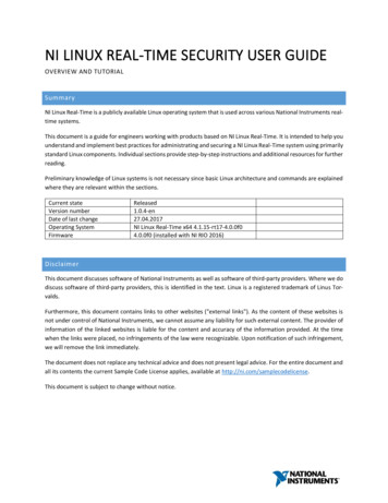
RV-C System Layout
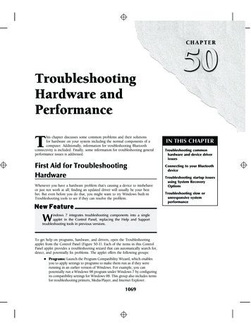
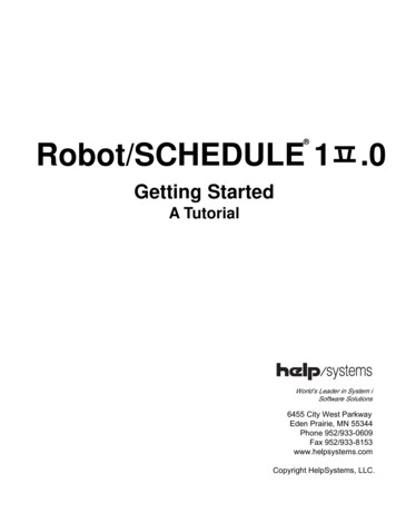
Interior Lighting I/OTanksBCM Pin ValuesExteriorLightingI/OPinNameBCM 62728Fresh 1 Tank InFresh 2 Tank InBlack 1 Tank InBlack 2 Tank InGray 1 Tank InGray 2 Tank InGray 3 Tank InTank CommonLight Group 1 12V Switch INLight Group 1 12V 15A INLight Group 1 GroundLight Group 1 12V 15A OutLight Group 2 12V Switch InLight Group 2 12V 15A InLight Group 2 GroundLight Group 2 12V 15A OutLight Group 3 12V Switch InLight Group 3 12V 15A InLight Group 3 GroundLight Group 3 12V 15A OutLight Group 4 12V Switch InLight Group 4 12V 15A InLight Group 4 GroundLight Group 4 12V 15A OutExterior Light 12V Switch InExterior Light 12V 15A InExterior Light GroundExterior Light 12V 15A OutInput from Sending UnitInput from Sending UnitInput from Sending UnitInput from Sending UnitInput from Sending UnitInput from Sending UnitInput from Sending Unit7 VDC Output to all TanksInputInputCommon GroundOutput 12VDC to LG 1InputInputCommon GroundOutput 12VDC to LG 2InputInputCommon GroundOutput 12V to LG 3InputInputCommon GroundOutput to LG 4InputInputCommon GroundOutput 12V to Exterior LightNoteA0-.74V EMPTY ( ).75-1.74V 1/3 ( )1.75-3.59V 2/3 ( )3.6V FULL ( )MEASURE FROM PIN 11 TO EACHINPUTFrom External Momentary SwitchFrom Main Breaker BoxFrom External Momentary SwitchFrom Main Breaker BoxFrom external Momentary SwitchFrom Main Breaker BoxFrom External Momentary SwitchFrom Main Breaker BoxFrom External Momentary SwitchFrom Main Breaker Box15ADMMVDCVDCVDCVDCVDCVDCVDC7 ND12VDC12VDC12VDCGND12VDC12VDC12VDCGND12VDC
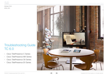
BCM Pin Values (Cont.)HYD NameBCM FunctionNote2930313233Security Light 12V Switch InSecurity Light 12V 15A INSecurity Light GroundSecurity Light 12V 15A OutFuel Station Tank Level InInputInputCommon GroundOutput 12V to Security LightInput from Sending UnitFrom External Momentary SwitchFrom Main Breaker Box34Fuel Station GNDGND35Generator Start Ground Out363738Generator Prime/Stop GroundOutGenerator Service 12V InGenerator Hour Meter 12V InGND Pass ThroughConnectionOutput Ground until buttonis releasedOutput Ground12VDC12VDC39Generator Fuel Level In12V Pulse Input12V Input triggers timer tostartInput from Sending Unit404143Generator Ground 12V Hydraulic Valve 1.5A(Landing Gear)Ground Hydraulic Valve(Landing Gear)Hydraulic Extend Out 12V 2A44Hydraulic Retract Out 12V 2A42Common GroundOutput 12VA12VDC12VDCGND12VDCΩ33 OHM FULL ( ),49 OHM 2/3 ( )127 OHM 1/3 ( ),240 OHM Empty ( )GNDGND33 OHM FULL ( ),49 OHM 2/3 ( )127 OHM 1/3 ( ),240 OHM Empty ( )Ω1.5ACommon GroundOutput 12V for ExtendValveOutput 12V for RetractValveDMMGND12VDCGND2AGND2AGND
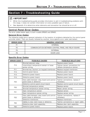
Alarm InputsAUX TriggersHYD SlidesBCM Pin Values (Cont.)WaterHeaterTravelLockoutPinNameBCM Function45Output 12V47484912V Hydraulic Valve 1.5A(Slide Solenoid)Ground Hydraulic Valve(Slide Solenoid)No ConnectionNo ConnectionTrigger 1 12V Out50Trigger 2 12V Out51Trigger 3 12V Out52Trigger 4 12V Out53Alarm 1 12V In54Alarm 2 12V In55Alarm 3 12V In56Alarm 4 12V In57Travel Lockout 12V In585960Water Heater GroundWater Heater Gas 12V 1A OutWater Heater Electric 12V 1AOutWater Heater 12V Fault In4661NoteA1.5ADMM12VDCCommon GroundGNDProgrammable 12V Latch orMomentaryProgrammable 12V Latch orMomentaryProgrammable 12V Latch orMomentaryProgrammable 12V Latch orMomentaryProgrammable 12V On orOff InputProgrammable 12V On orOff InputProgrammable 12V On orOff InputProgrammable 12V On orOff Input12V Input from Tow VehicleBrake signal12VDCCommon Ground12V Output to Gas Ignitor12V Output to ElectricIgnitorReceive 12V Fault Signal12VDC1A12VDC12VDC12VDC12VDC1A12VDC12VDCLocks out all motor functionswhen signal is present12VDC1AGND12VDC12VDC12VDC
BCM Pin Values ic SlideMotorsJacksPinNameBCM 818283848586878889Awning Light 12V Switch InAwning Light 12V 3A OutAwning Light GroundWater Pump 12V 10A OutWater Pump GroundWater Pump 12V 15A InAwning 2 Retract OutAwning 2 Extend OutAwning 1 Retract OutAwning 1 Extend OutRear Jack Retract OutRear Jack Extend OutFront Jack Retract OutFront Jack Extend OutSlide 5 Retract OutSlide 5 Extend OutSlide 4 Retract OutSlide 4 Extend OutSlide 3 Retract OutSlide 3 Extend OutSlide 2 Retract OutSlide 2 Extend OutSlide 1 Retract OutSlide 1 Extend OutGround InPower Chassis 12V InAwning Power 12V 15A InElectric Slide/Jack Power 12V30A INMain Power 12V 15A InInputOutput 12V to Awning LightCommon GroundOutput 12V to Water PumpCommon tOutputOutputOutputInputInputInputInputFrom External Momentary SwitchPower from Awning 15A InputFrom Main Breaker BoxReversing Polarity DC MotorReversing Polarity DC MotorReversing Polarity DC MotorReversing Polarity DC MotorReversing Polarity DC MotorReversing Polarity DC MotorReversing Polarity DC MotorReversing Polarity DC MotorReversing Polarity DC MotorReversing Polarity DC MotorReversing Polarity DC MotorReversing Polarity DC MotorReversing Polarity DC MotorReversing Polarity DC MotorReversing Polarity DC MotorReversing Polarity DC MotorReversing Polarity DC MotorReversing Polarity DC MotorFrom Chassis GroundFrom Chassis Battery (Motorized)From Main Breaker BoxFrom 12V 30A mini reset D12V/GND12V/GNDGND12VDC12VDC12VDCInputFrom Main Breaker Box15A12VDC90A3A10A15A30ADMM
NCSP3 Functionality TestThe Body Control Module (BCM) should be wired correctly, withoutloose connections, and connected to 12 VDC at pin 90. A RED LED willindicate that the BCM is receiving 12 VDC.The 2 toggle switches on the BCM correspond to the 2 dialsunderneath them. (In the event where communication between theDisplay Commander (DC) and BCM is non-functioning, these switcheswill enable "manual" functions of the selected devices) The Leftswitch and knob are used for Electric Awnings and Jacks. (HydraulicJacks are manually controlled at the Hydraulic Pump. See theHydraulic Pump Manual Override in the RV owner's manual), and theRight switch and knob are used for Electric Slides 1 - 5.The BCM and DC communicate with each other through an RV-C (CANBUS) connection. This RV-C communication also allows the DC toconnect to a third party AC translator module (gateway) so that youcan perform the HVAC functions from the DC.The Display Commander (DC) will be mounted in an "all access" areanear the entrance. On the DC, press and release the Power button(the left button) to wake up the DC. After a moment, the PasscodeScreen will appear. Enter your Passcode. If this is the first time the DChas been powered on, an End User License Agreement (EULA) screenwill appear. Upon accepting the EULA, an “Enter New Passcode”screen will appear. Enter your new passcode and confirm.The DC will now bring up the Home Screen If the Floor Plan has beenloaded, all of the devices should be listed with correspondingactitation buttons
Go through all the functions and make sure they are operating properly. Allthe functions should be smooth and instantaneous. Ensure all the HomePage Hot keys actuate/turn on the corresponding functions.Cycle the Generator. When the Generator is being cycled for the firsttime (or if it has been a while since it has been used), it will need tobe primed. Hold the Prime button down to 2 -5 seconds, then pressand hold the Start button down until the generator starts.iN-Command is also equipped with an Auto Gen start. Press the“Manual” button to switch to “Auto” to activate the Auto Gen startfunction. If the battery voltage is less than 11.8V for 3 minutes, thesystem will start the generator. If the generator is started, thegenerator will run for 60 Minutes. Also, the system will attempt tostart the generator 3 times. If the generator fails to start after the 3rdattempt, the system will turn off the Auto feature and display a“Check Generator” Fault Message.HVAC TestingWhen testing the HVAC (Climate Function), make sure each “Zone” isdisplaying a room (Zone) temperature. Use the “Mode” button tocycle through Fan, Cool, Heat and Auto modes. (Heat and Automodes availability depend on the floor plan.)
Use the “Set” temperature up and down arrows to set the desiredtemperature. The “Set” temperature can be adjusted between 55 to 90F.Please review the NCSP3 User Manual for further HVAC operationalinstructions. You can scan the QR code shown below or use thefollowing link: wners-manual ncsp3.pdf
TroubleshootingHVAC (Dometic Systems) If the room temp reads 100F, remove the roomsensor cover and pull the room sensor out of the holding clip. Thetemp should read normally. Adjust the holding clip down on theroom sensor so that it is not pinching it.(RVP Systems) If the room temp reads 111F, the room sensor wasconnected to the cool shed connections on the RVP control box.Swap the wires between the cool shed and room sensor pins. Theroom temp should start reading correctly without a reset.(Both Systems)If no HVAC function, check to see if the room (zone)temp is blank. If it is, make sure the RV-C cables are connected tothe gateways and make sure there is an EOL (End of Line)terminator resistor at the last gateway in the line. Make sure theaddress on the gateway is correct. If that is correct, redo thepower, ground and communication wires between the gateway andcontrol box. Verify the gateway has proper 12VDC.(Dometic)If there are multiple rapid clinking sounds when operatingthe furnace function, the gateway has old software and needs to beswapped out.(Dometic)If a zone will not change functions (i.e. stuck on furnacemode), try adjusting the fan speed. Most likely it will show Auto, tryand get it to either low or high. This indicates the gateway is in alocked state. If you can get the fan mode to change, you shouldthen be able to change the zone function to off. Once it stays in offmode, power cycling the system.If changing an HVAC function in a Zone, and the function changes ina different zone, the dip switches are not set correctly. The front ACis Zone 1, middle is Zone 2 and rear is Zone 3.(RV-C) Communication issues Make sure the CAN-Low does not have a short to 12V.Make sure the CAN-High does not have a short to ground.Make sure there is not a short between CAN-Low and CAN-High.Check RV-C plugs and pins to make sure there is not a looseconnection. Try and power cycle all the components.Make sure the RV-C connector is pinned correctly.Try a different RV-C cable.Press the reset button on the BCM.If the generator or auxiliary fuel I/O’s from the BCM are connecteddirectly to 12VDC, all low current functions on the BCM will notoperate properly. I.E: The RV-C will not communicate properly andthe water tanks will not read correctly.No BCM Power Check if the Red Power indicator is lit.Press the reset button on the BCM.Verify 12V on Pin 90 and Ground on pin 86.Check Fuse in Main Breaker Box.Cycle RV Power at the Main Breaker Box.No DC Power Cycle power with the Power Button. (Press and hold thepower button for 5 seconds.)Verify 12V and Ground at the back of the DC.Verify no blown fuses in the Main Breaker Box.
Slide Rooms do not move Verify 12V on pin 89.If the Battery Disconnect switch is off, turn it on. (Somemodels pull the slide power through the battery disconnect.) Awnings do not move Verify 12V on pin 88.Check fuse in Main Breaker Box. Water Tank Make sure the common pin (Pin 8) is outputting 7VDC. If novoltage, disconnect the tank harness and test the pin on the BCM. Ifthere is voltage now, that indicates the common wire has a short toground.If one of the tanks is reading, but another tank does not read,remove the wires from the bell caps and swap the tank wires. If theopposite tank now reads, that indicates the BCM is fine and there isan issue in the tank line.The tank level voltages are as follows:o 1/3: .75 to 1.74o 2/3: 1.75 to 3.59o 3/3: 3.6 and aboveMain power Pin 90. Then press the Gen Start button on theDC. The voltage reading on the DMM will jump to fullvoltage if the circuit is working correctly.If the generator prime/stop function does not work:o Make sure the Gen Prime/Stop wire (Pin 36, yellow) ismaking a good connection.o To check the signal output, connect the negative lead froma DMM (volt multi-meter) to Pin 36 and the positive lead toMain power Pin 90. Then press the Gen Start button on theDC. The voltage reading on the DMM will jump to fullvoltage if the circuit is working correctly.The generator is running, but the start button has not switched tostop and the hour meter is not counting:o Make sure the Gen Hour Meter wire (Pin 38, blue) is makinga good connection.o If the generator is running, the generator should beoutputting a 12V signal to the Hour Meter input Pin 38 onthe BCM. If no voltage present, check signal fromgenerator.Note: The DC will display generator fault codes provided by the generator.If you get a generator fault popup (like “Low Oil”), consult the generatorowner’s manual for further troubleshooting on the generator.Generator If the generator will not start:o Make sure the Gen Start wire (Pin 35, orange) is making agood connection.o To check the signal output, connect the negative lead froma DMM (volt multi-meter) to Pin 35 and the positive lead toFor additional troubleshooting, call ASA Electronics Technical Support at 1877-845-8750, email info@asaelectronics.com or visit our iN-Commandsupport page at https://in-command.net/
Troubleshooting HVAC (Dometic Systems) If the room temp reads 100F, remove the room sensor cover and pull the room sensor out of the holding clip. The temp should read normally. Adjust the holding clip down on the room sensor so that it is not pinching it. (RVP