Transcription
EE126 Lab 1, Fall 2006VHDL, Verilog, and the Altera environment TutorialTable of Contents1. Create a new Project2. Example Project 1: Full Adder in VHDL3. Code Compilation4. Pin Assignment5. Simulating the Designed Circuit6. Programming and Configuring the FPGA Device7. Example Project 2: Full Adder in Verilog8. Lab 1 Assignment9. Lab Report GuidelinesAppendix A: VHDL and Verilog Standard FormatsThis tutorial is intended to familiarize you with the Altera environment andintroduce the hardware description languages VHDL and Verilog. The tutorial will stepyou through the implementation and simulations of a full-adder in both languages. Usingthis background you will implement a four-bit adder in both VHDL and Verilog. In thefuture, HDL labs can be done in either language.You may want to refer to Appendix A to review the standard structures of VHDLand Verilog modules.
1. Create a new ProjectOn starting Altera Quartus II, you should be faced with a screen like this:Figure 1. The main Quartus II display.Go to "File - New Project Wizard". A introduction Dialog will appear (Fig 2), Itindicates the capability of this wizard. You can skip this window in subsequent projectsby checking the box Don’t show me this introduction again.
Figure. 2 Tasks performed by the wizard.Press Next to get the window shown in Figure 3. Choose the location of your workingdirectory and type in the name of your project (let’s use fulladder) as shown in Fig. 3.
Figure. 3 Creation of a new project.Press Next. Since we have not yet created the directory lab1, Quartus II softwaredisplays the pop-up box in Figure 4 asking if it should create the desired directory.Figure. 4 Quartus II software can create a new directory for the project.Click Yes, which leads to the windows in Figure 5.
Figure 5. The wizard can include user-specified design files.The wizard makes it easy to specify which existing files (if any) should be included in theproject. Assuming that we do not have any existing files, click Next, which leads to thewindow in Figure 6
.Figure 6. Choose the device family and a specific device.We have to specify the type of device in which the designed circuit will be implemented.Choose Cyclone II as the target device family. We can let Quartus II software select aspecific device in the family, or we can choose the device explicitly. We will take thelatter approach. From the list of available devices, choose the device calledEP2C35F672C6 which is the FPGA used on Altera’s DE2 board. Press Next, whichopens the window in Figure 7.
Figure 7. Other EDA tools can be specified.The user can specify any third-party tools that should be used. A commonly used term forCAD software for electronic circuits is EDA tools, where the acronym stands forElectronic Design Automation. This term is used in Quartus II messages that refer tothird-party tools, which are the tools developed and marketed by companies other thanAltera. Since we will rely solely on Quartus II tools, we will not choose any other tools.Press Next.A summary of the chosen settings appears in the screen shown in Figure 8. Press Finish,which returns to the main Quartus II window, but with lab1 YOURNAME specified asthe new project, in the display title bar.
Figure 8. Summary of the project settings.
2. Example Project 1: Full Adder in VHDLSelect “File New” to get the window in Figure 9, choose VHDL File, and click OK.This opens the Text Editor window. The first step is to specify a name for the file thatwill be created. Select File Save As to open the pop-up box depicted in Figure 10. Inthe box labeled Save as type choose VHDL File. In the box labeled File name enterfulladder. Put a checkmark in the box Add file to current project. Click Save, whichputs the file into the directory lab1. Maximize the Text Editor window and enter theVHDL code as shown in Figure 11. Save the file by typing File Save, or by typing theshortcut Ctrl-s.Figure 9. Choose to prepare a VHDL file.
Figure 10. Name the fileFigure 11. fulladder VHDL code.
NOTE:-- Constant can be used to declare a constant of a particular type. In this case, Time.-- The functional relation between the input and output signals is described by thearchitecture body.-- Only one architecture body should be bound to an entity, although manyarchitecture bodies can be defined.The syntax of VHDL code is sometimes difficult for a designer to remember. Tohelp with this issue, the Text Editor provides a collection of VHDL templates. Thetemplates provide examples of various types of VHDL statements, such as an ENTITYdeclaration, a CASE statement, and assignment statements. It is worthwhile to browsethrough the templates by selecting Edit Insert Template VHDL to become familiarwith this resource.3. Code CompilationThe code in the file fulladder is processed by several Quartus II tools thatanalyze the code, synthesize the circuit, and generate an implementation of it for thetarget chip. These tools are controlled by the application program called the Compiler.Run the Compiler by selecting Processing Start Compilation, or by clicking on thetoolbar iconthat looks like a purple triangle. As the compilation moves throughvarious stages, its progress is reported in a window on the left side of the Quartus IIdisplay. Successful (or unsuccessful) compilation is indicated in a pop-up box.Acknowledge it by clicking OK, which leads to the Quartus II display in Figure 12. Inthe message window, at the bottom of the figure, various messages are displayed. In caseof errors, there will be appropriate messages given. When the compilation is finished, acompilation report is produced. A window showing this report is opened automatically,as seen in Figure 12. The window can be resized, maximized, or closed in the normalway, and it can be opened at any time either by selecting Processing CompilationReport or by clicking on the icon.
Figure 12. Display after a successful compilation.4. Pin AssignmentThe DE2 board has hardwired connections between the FPGA pins and the othercomponents on the board. We will use two toggle switches, labeled SW0, SW1and SW2,to provide the external inputs, a, b and cin, to our example circuit. These switches areconnected to the FPGA pins N25, N26 and P25, respectively. We will connect the outputsum and cout to the green light-emitting diodes labeled LEDG0 and LEDG1, which ishardwired to the FPGA pin AE22 and AF22.Pin assignments are made by using the Assignment Editor. Select Assignments Assignment Editor to reach the window in Figure 13. Enter the pin assignment as shownin Figure 13. Recompile the circuit, so that it will be compiled with the correct pinassignments.
Figure 13 The Assignment Editor window.You can import a pin assignment by choosing Assignments Import Assignments.This opens the dialogue in Figure 14 to select the file to import. Type the name of the file,including the csv extension and the full path to the directory that holds the file, in the FileName box and press OK. Of course, you can also browse to find the desired file.Figure 14. Importing the pin assignment.For convenience when using large designs, all relevant pin assignments for the DE2board are given in the file called DE2 pin assignments.csv. If we wanted to make thepin assignments for our example circuit by importing this file, then we would have to usethe same names in our VHDL design file; namely, SW(0), SW(1), SW(3) and LEDG(0),LEDG(1) for a, b, cin, sum and cout, respectively. Since these signals are specified in the
DE2 pin assignments.csv file as elements of arrays SW and LEDG, we must refer tothem in the same way in the design file. For example, in the DE2 pin assignments.csvfile the 18 toggle switches are called SW[17] to SW[0]; since VHDL uses parenthesesrather than square brackets, these switches are referred to as SW(17) to SW(0). They canalso be referred to as an array SW(17 downto 0).5. Simulating the Designed CircuitBefore implementing the designed circuit in the FPGA chip on the DE2 board, it isprudent to simulate it to ascertain its correctness. Quartus II software includes asimulation tool that can be used to simulate the behavior of a designed circuit. Before thecircuit can be simulated, it is necessary to create the desired waveforms, called testvectors, to represent the input signals. It is also necessary to specify which outputs, aswell as possible internal points in the circuit, the designer wishes to observe. Thesimulator applies the test vectors to a model of the implemented circuit and determinesthe expected response. We will use the Quartus II Waveform Editor to draw the testvectors, as follows:Open the Waveform Editor window by selecting File New. Click on the OtherFiles tab to reach the window displayed in Figure 15. Choose Vector Waveform Fileand click OK.Figure 15. Choose to prepare a test-vector file.The Waveform Editor window is depicted in Figure 16. Save the file under thename fulladder.vwf. Set the desired simulation to run from 0 to 20 ns by selecting Edit End Time and entering 20 ns in the dialog box that pops up. Selecting View Fit inWindow displays the entire simulation range of 0 to 20 ns in the window.
Figure 16. The Waveform Editor window.Next, we want to include the input and output nodes of the circuit to be simulated. ClickEdit Insert Node or Bus to open the window in Figure 17. It is possible to type thename of a signal (pin) into the Name box, but it is easier to click on the button labeledNode Finder to open the window in Figure 18. The Node Finder utility has a filter usedto indicate what type of nodes are to be found. Since we are interested in input and outputpins, set the filter to Pins: all. Click the List button to find the input and output nodes asindicated on the left side of the figure. Select all signals and click the sign to add it tothe Selected Nodes box on the right side of the figure. Click Ok to close the Node FinderWindow and then Ok in the window of Figure 17. This leaves a fully displayedWaveform Editor window, as shown in Figure 19.Figure 17. The Insert Node or Bus dialogue.Figure 18. Selecting nodes to insert into the Waveform Editor.
Figure 19. The nodes needed for simulation.Select signal a by first select the icon , then click signal a”. Then click the icontobring up Figure 20 and fill in values as shown in that figure. Do the same to signal b andcin by using period of 1000ps and 2000ps respectively. Then save the file.Figure 20. Clock waveform setting for aA designed circuit can be simulated in two ways. The simplest way is to assume thatlogic elements and interconnection wires in the FPGA are perfect, thus causing no delayin propagation of signals through the circuit. This is called functional simulation. A morecomplex alternative is to take all propagation delays into account, which leads to timingsimulation. Typically, functional simulation is used to verify the functional correctness ofa circuit as it is being designed. This takes much less time, because the simulation can beperformed simply by using the logic expressions that define the circuit.To perform the functional simulation, select Assignments Settings to open the Settingswindow. On the left side of this window click on Simulator to display the window inFigure 21, choose Functional as the simulation mode, and click OK. The Quartus II
simulator takes the inputs and generates the outputs defined in the fulladder.vwf file.Before running the functional simulation it is necessary to create the required netlist,which is done by selecting Processing Generate Functional Simulation Netlist. Asimulation run is started by Processing Start Simulation, or by using the icon . Atthe end of the simulation, Quartus II software indicates its successful completion anddisplays a Simulation Report illustrated in Figure 22.Figure 21. Specifying the simulation mode.Figure 22. The result of functional simulation.
Having ascertained that the designed circuit is functionally correct, we should nowperform the timing simulation to see how it will behave when it is actually implementedin the chosen FPGA device. Select Assignments Settings Simulator to get to thewindow in Figure 21, choose Timing as the simulation mode, and click OK. Run thesimulator, which should produce the waveforms in Figure 23.Figure 23. The result of timing simulation.6. Programming and Configuring the FPGA DeviceThe programming and configuration task is performed as follows. Flip the RUN/PROGswitch (on DE2 Board) into the RUN position. Select Tools Programmer to reach thewindow in Figure 24. Here it is necessary to specify the programming hardware and themode that should be used. If not already chosen by default, select JTAG in the Mode box.Also, if the USB-Blaster is not chosen by default, press the Hardware Setup. button andselect the USB-Blaster in the window that pops up, as shown in Figure 25.Figure 24. The Programmer window.
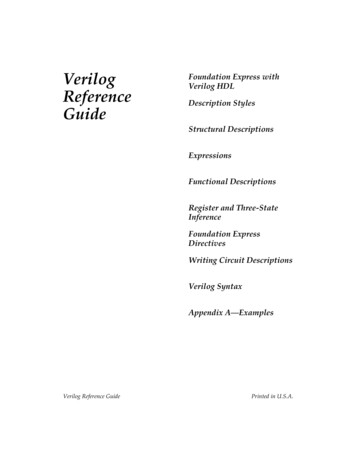
Figure 25. The updated Programmer window.Observe that the configuration file fulladder.sof is listed in the window in Figure 24. Ifthe file is not already listed, then click Add File and select it. This is a binary fileproduced by the Compiler’s Assembler module, which contains the data needed toconfigure the FPGA device. The extension .sof stands for SRAM Object File. Note alsothat the device selected is EP2C35F672, which is the FPGA device used on the DE2board. Click on the Program/Configure check box, as shown in Figure 24. Now, pressStart in the window in Figure 24. An LED on the board will light up when theconfiguration data has been downloaded successfully. If you see an error reported byQuartus II software indicating that programming failed, then check to ensure that theboard is properly powered on.7. Example Project 2: Full Adder in VerilogFollow the step 1 to create a new project but with a different name (ex:fulladder2). Click File New to bring up the dialog as shown in Figure 26 and selectVerilog HDL File and Click OK. Enter the code as shown in Figure 27. In Verilog, amodule’s inputs and outputs are listed at least twice – once in the IO list following themodule name, and again inside the module where they are assigned a direction.Verilog module outputs need to be registered. That is to say, the result of a logicalexpression cannot be sent directly to an output pin, but must first be buffered by a register.This is accomplished by declaring a register with the same name as the signal.Since “sum” and “cout” are output pins, add registers as shown in Figure 27. Refer toTable 1 for the Verilog syntax of common logical operators.
Figure 26. Create new Verilog FileFigure 27 Verilog Code
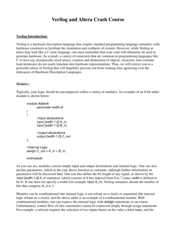
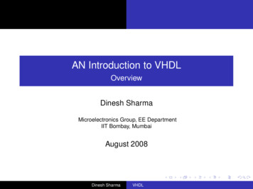
Table 1. Basic Verilog OperatorNote that the expressions for “sum” and “cout” are placed in an always block. An alwaysblock is executed any time one of the signals in the sensitivity list (“a” or b or cin” in thiscase) changes. This tells the synthesizer to update the “sum” and “cout” registers onlywhen an input changes.The procedure for synthesizing and simulating the fulladder module is the same as in theVHDL section.8. Lab 1 AssignmentIn both VHDL and Verilog, use the full-adder modules created in the above tutorials toimplement four-bit adder modules with the architecture shown in figure 19. To do this,create a new source in the project where you designed the fulladder. You will have todeclare multi-bit signals and instantiate the fulladder modules in this new source.Connect the “cout” pin of each full-adder to the “cin” pin of the next.Refer to Appendix A for module instantiation format, multi-bit signal declarations etc.Figure 19Once the four-bit adder is able to synthesize, run Simulator to test your design. Step thesimulation with several different input combinations and verify the adder’s functionality.Record results and/or take some screenshots.9. Lab Report GuidelinesPlease write up a report on the HDL implementation and simulation of the four-bit adderscreated in this lab. The lab report should at least include a purpose, procedure, results,and conclusion. Please include all HDL in an appendix.
Appendix A: VHDL and Verilog Standard FormatsStandard Structure of a VHDL Designentity entity name isPort(signal0 : in std logic;signal1 : out std logic; signaln : out std logic vector (3 downto 0));end entity name;architecture Behavioral of entity name is-- component declarationscomponent comp name isPort(a : in std logic; );end component;-- signal declarationssignal wire0, wire1 : std logic;-- main blockbegin-- behavioral and/or structural code here.-- module instantiationinstance name: comp nameport map(signal0, signal1, );-- logical operationssignal3 (signal4 and signal5) xor signal8;end
Standard Structure of a Verilog Designmodule module name(signal0,signal1, ,signaln);// module signalsinput signal0;output [15:0] signal1; output signaln;// internal registersreg register0;reg signal1;// internal signalswire wire0;wire wire1;// behavioral and/or structural code here.// module instantiationmodule name1 instance name1 (signal0, signal1);// logical operationsalways @ (signal4 or signal5 or signal8)beginsignal3 (signal4 && signal5) signal8;endendmodule
VHDL, Verilog, and the Altera environment Tutorial Table of Contents 1. Create a new Project 2. Example Project 1: Full Adder in VHDL 3. Code Compilation 4. Pin Assignment 5. Simulating the Designed Circuit 6. Programming and Configuring the FPGA Device 7. Example Project 2: Full Adde