Transcription
Verilog and Altera Crash CourseVerilog Introduction:Verilog is a hardware description language that couples standard programming language semantics withhardware constructs to facilitate the simulation and synthesis of circuits. However, while Verilog attimes may look like a C-style language, one must remember that your code will ultimately be used togenerate hardware. As a result, a variety of constructs that are common in programming languages likeC or Java (eg. dynamically sized arrays, creation and destruction of objects, recursion, non-constantloop iterations) do not easily translate into hardware representations. Thus, we will restrict you to apowerful subset of Verilog that will hopefully prevent you from wasting time agonizing over theintricacies of Hardware Description Languages.Modules:Typically, your logic should be encompassed within a variety of modules. An example of an 8-bit addermodule is shown below:module Adder#(parameter width 8)(//input declarationsinput [width-1:0] A in,input [width-1:0] B in,//output declarationsoutput [width-1:0] C out);//Internal Logicassign C out A in B in;endmoduleAs you can see, modules consist simply input and output declarations and internal logic. One can alsodeclare parameters, which in the case above function as constants, although further information onparameters will be discussed later. One can also define the bit length of any signal, as shown by theinput [width-1:0] A in statement, which consists of 8 bits indexed from 0 to 7 (since width is defined tobe 8). If one does not specify a width (for example input A in), Verilog semantics dictate the number ofbits that comprise A in is 1.Modules can be combinational (the internal logic is not reliant on a clock) or sequential (the internallogic reliant on a clock), and the above adder is an example of a combinational module. Withcombinational modules, one can express the internal logic with assign statements, to an extent.Unfortunately, control flow (if-else statements) cannot be expressed simply through assign statements.For example, a selector requires the selection of two inputs based on the value a third input, and the
resulting module is shown below:module Selector#(parameter width 8)(//input declarationsinput [width-1:0] A in,input [width-1:0] B in,input select,//output declarationsoutput reg [width-1:0] C out);//Internal Logicalways @(*)beginif (select)beginC out B in;endelsebeginC out A in;endendendmoduleHere, the internal logic is enclosed within an always @(*) block, which simply means that thestatements within the begin and end tokens constitute a combinational block.Not all circuits, however, are combinational. Sequential circuits (those that depend on a clock input)can be constructed as shown below:module Register(input CLK,input D in,output reg O out);always @(posedge CLK)beginO out D in;endendmodule
As you have probably noticed, sequential modules require an always @(posedge CLK) declaration,which means that the statements within the begin and end tokens will occur when the CLK signaltransitions from 0 to 1.Blocking vs. Nonblocking Assignments:You may have also noticed one other difference, namely the “nonblocking assignment” O out D in.This looks different from what you are probably used to, which would probably look something likeO out D in. In Verilog, these two types of assignments have very different semantics. Take forexample the following:always @(posedge CLK)begina b;b a;endThe above code is an example of “blocking assignments.” Let's assume that, before we execute thealways block, a 1, and b 0. If the above code was executed in a language like C, the firstassignment would happen, resulting in a being set to 0, and the subsequent assignment of a to b willresult in b being set back to its original value of 0. This is because the blocking semantics of the “ ”operator results in lines being executed in order.However, if we turn our attention to the following line of code, we will see some different behavior:always @(posedge CLK)begina b;b a;endHere, the “ ” operator results in nonblocking semantics, which means that all assignments within theblock occur in parallel. This means that, if a 1, and b 0 before the block executes, after the firstclock edge, the assignment of b to a will occur at the same time. This will result in a obtaining thevalue of 0 and b obtaining the value of 1.Intermediate Signals:Like all C-style languages, Verilog provides the ability to declare intermediate variables of a variety oftypes within a module. We recommend you restrict yourself to two types, reg and wire. The majordifference between these two types is that signals of type wire cannot be assigned within a begin-endblock, whereas signals of type reg can only be assigned within a begin-end block. For example, thefollowing code is valid:
wire a;wire b;reg c;assign a b;always @(*)beginc a;endOn the other hand, the following code is invalid, as it contains a reg type being assigned outside of abegin-end block and a wire type being assigned within one.wire a;wire b;reg c;assign c a;always @(*)beginb a;endInstantiating Modules:At some point, you may want to use a module that you write. For example, let’s say we wanted to usethe adder and selector that we defined earlier in a new module. An example of how to do this is shownon the next page.
module AdderShift#(parameter width 11)(input [width-1:0] a in,input [width-1:0] b in,input shift in,output [width-1:0] o out);wire [width-1:0] adder out;wire [width-1:0] adder out shift adder out 2;Adder #(.width(width)) adder (.A in(a in),.B in(b in),.C out(adder out));Selector#(.width(width)) selector (.A in(adder out),.B in(adder out shift),.select(shift in),.C out(o out));endmoduleAs we can see, module declarations require both a module type and name. One can also set theparameters of the module externally. For example, the parameter width for both the Adder and Selectormodules is set to be 11, even though when we declared it that parameter was set to 8. Verilog semanticsdictate that the outermost module’s parameter definition will propagate into the child module, whichmeans that the instantiation of our Adder and Selector will have its width parameter set to 11 since theoutermost module, AdderShift, set it to be 11.To connect the inputs, outputs, and parameters, it is more reliable to utilize the syntax used above. Forexample, when connecting the adder out wire to the A in pin of our Selector, we use the followingsyntax: .A in(adder out). This will unambiguously specify which inputs and wires are connected, andit can automatically adjust the bit-width if the sizes do not match exactly.
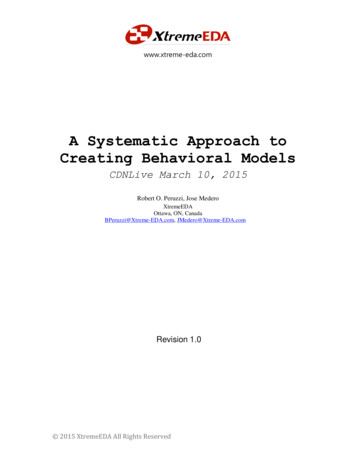
Altera Tools Introduction:Now that you have gotten acquainted with Verilog, it is time to learn how you can verify that yourVerilog code is well-formed. In this class, you will use the Altera tools, which should be in the labcomputers in the basement. The two tools you will use will be Quartus and Modelsim. While the toolsare quite powerful, they have a rather steep learning curve, so we hope that the following tutorial willalleviate this somewhat.Quartus Introduction:If you are in the lab basement computers, you can find Quartus by going to Start All Programs Altera 12.0 Build 178 Quartus II 12.0sp2 Quartus II 12.0sp2 (32-bit). When the Quartus windowcomes up, perform the following steps:1. Select the New Project Wizard.2. Click Next3. Specify the project directory (probably a directory on your Desktop) and project name. ClickNext.4. If you have Verilog files, you can add them, but if not, just click Next.5. In this class, we will target the Cyclone II EP2C20F484C7, so enter that into the window, selectthat FPGA, and click Next.6. Make sure that the Simulation Tool Name is “ModelSim-Altera” and the Format is “Verilog.”Click Next.7. Click Finish.You should now have a window like the following:
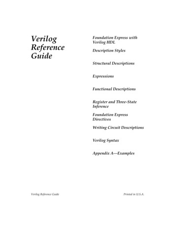
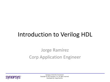
To create a Verilog file, go to File New, and then select Verilog HDL File. You can then write yourVerilog through Quartus’ IDE. For example, you can copy the Adder code that is shown on Page 1.Save your file in the same directory that you specified in step 3 from above, and you will now see yourVerilog file listed under the Files tab on the left. Right click the file and click “Set as Top-Level Entity”so that you can synthesize it. To synthesize your file, go to Processing Start Compilation. Check theconsole at the bottom for any errors to fix if you have them.If you want to include other modules in your project, you can create or import them. For example, ifyou create two new files and copy in the Selector and AdderShift modules to each of them, and if youset the top level module to AdderShift, then you will be able to compile all three modules into a singlecircuit. You can view a schematic of your code by selecting Tools Netlist Viewers RTL Viewer.For example, the RTL viewer for my AdderShift module looks as follows:
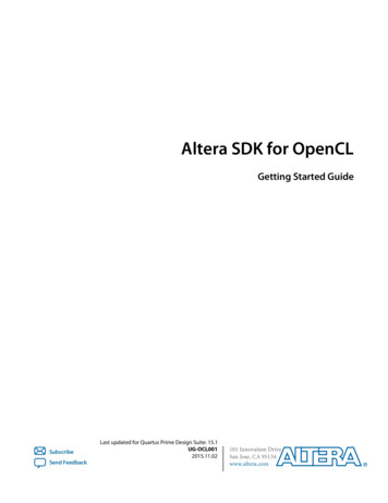
Modelsim Introduction:There are many ways to start Modelsim, but the easiest way is through Quartus. After you synthesizeyour circuit, go to Tools Run Simulation RTL Simulation. When you do this, Quartus will supplyModelsim with the appropriate commands to create directories and set paths, mitigating the need foryou to handle such tasks. If you do so for the aforementioned AdderShift module, you should seesomething like the following on your screen:
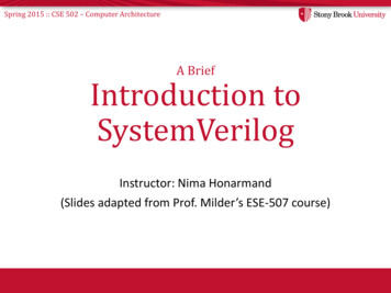
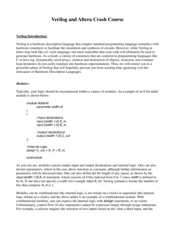
In the Modelsim window, expand the “work” library, and you should see your Verilog files. Right clickthe top-most module and click “Simulate” in order to simulate your Verilog. Click View Wave to seethe waveform window. Your resulting window should look something like this:If you do not see this, check your Transcript window at the bottom to verify that all of your code wasable to compile without errors.To actually view the signals on the waveform, you need to drag them from the Objects window ontothe Wave window. You can then set values for the inputs by right clicking them, clicking “Force,” andsetting the value. To simulate, go to Simulate Run Run 100. You should see green lines and whitenumbers appear on the waveform, similar to the following:
Testbenches:Forcing signals every time you simulate can be quite cumbersome, especially if your circuit has a largenumber of inputs. You can automate the testing of your circuit by writing testbenches, which are simplywrapper modules that instantiate and supply inputs to your circuit. Here is an example of a testbenchfor the AdderShift module previously provided: timescale 1ns/1psmodule AdderShiftTest();parameter width 11;reg [width-1:0] a in;reg [width-1:0] b in;reg shift in;wire [width-1:0] o out;AdderShift#(.width(width)) addershift(.a in( a in),.b in(b in),.shift in(shift in),.o out(o out));initial begina in 11’h012;b in 11’h123;shift in 0;#1shift in 1;#1a in 11’h014;b in 11’h023;endendmodule
You can add this module in Modelsim by clicking Compile Compile and navigating to the Verilogfile containing the above code. You can them right click it and simulate it. After dragging the relevantsignals to the Wave window, you should be able to simulate it and obtain the following in yourwaveform:Further reading:This handout is in no way comprehensive regarding the intricacies of Quartus, Modelsim, or Verilog,but it should provide a solid starting point for writing the Verilog that you will need to generate in thiscourse. If you want a more comprehensive tutorial, you can check out the following links:ftp://ftp.altera.com/up/pub/Altera Material/10.1/Tutorials/Verilog/Quartus II 3/cse140L-a/modelsim -a/02-VerilogFundametals.pdf
Verilog through Quartus’ IDE. AdderFor example, you can copy the code that is shown on Page 1. Save your file in the same directory that you specified in step 3 from above, and you will now see your Verilog file listed under the Files tab on the left. Right click the file and click