Transcription
www.xtreme-eda.comA Systematic Approach toCreating Behavioral ModelsCDNLive March 10, 2015Robert O. Peruzzi, Jose MederoXtremeEDAOttawa, ON, CanadaBPeruzzi@Xtreme-EDA.com, JMedero@Xtreme-EDA.comRevision 1.0 2015 XtremeEDA All Rights Reserved
SYSTEMATIC APPROACH TO BEHAVIORAL MODELINGCDNLIVE, MARCH 10, 2015ABSTRACTWe present a systematic approach for creating accurate analogand mixed-signal (AMS) behavioral models for system design andverification. Our approach reduces the risk of system failureresulting from model error, whether model error comes frominitial misunderstanding or miscommunication of designrevision. This paper, which accompanies a CDNLive presentationof the same title is targeted toward model designers, but isof interest to verification engineers, circuit designers, andengineering managers.Although our approach is platform-independent, we demonstrateour procedure using the Cadence Design System. Virtuoso is thestarting point for generating models and test benches. We makeuse of AMSDMV (Analog Mixed-Signal Design and ModelValidation) and we define interactive procedures for modelcreation, validation, and maintenance based upon expectedbehavior. This approach applies to any modeling language,including Verilog or System Verilog using real number modeling(RNM), Verilog-AMS (including WREAL), and Verilog-A. And formodels intended for UVM, Verilog, or Verilog-AMS simulationplatforms.Between them, the authors have more than 40 years’ behavioralmodeling experience. This paper shares the approach theydeveloped first individually at various companies and thencollaboratively at XtremeEDA.1. INTRODUCTION1.1.INDUSTRY TRENDS AND OBSERVATIONSAs of 2015, System-on-Chip (SOC) size and complexity continuesto increase [1], because traditional economic drivers remainin place such as reduced physical dimensions, extended batterylife, and lower price for end product. Analog and mixed signal(AMS) content continue to be brought onboard the SOC despitethe difficulty for analog performance not to degrade asgeometry shrinks in advanced nodes. In fact, 2015 XtremeEDA All Rights ReservedPAGE 2
SYSTEMATIC APPROACH TO BEHAVIORAL MODELINGCDNLIVE, MARCH 10, 2015IBS reports that mixed signal accounts for over85% of chip design starts in 2014, and thatpercentage will rise, and hold steady at 85% inthe coming years [2]The 2013 prediction [3] was that 130nm would continue to bethe most popular AMS technology node. Meanwhile, 65nm is nowconsidered mainstream [4], and the number of 28nm tape-outsand designs in progress is increasing. As of 2013, analogdesign problems at less than 28nm had yet to be solved [5].The accepted solution is to use digital compensation andcalibration in analog building blocks.Time to market remains all-important. This conflicts with therequirement that verification quality must not degrade. Theconflict is resolved by simulator performance increasing.Digital design and analog design follow fundamentallydifferent procedures. Each flow has unique requirements, toolsand skills. Thus the design teams are separated in outlook ifnot geographically. The gap must be bridged to successfullybring a mixed signal SOC to market. The interface betweenanalog and digital circuitry is a likely place for faults tooccur.1.2.INDUSTRY CHALLENGESBeyond the physical challenges of mixed-signal design in nanoscale technology is the verification challenge ofmanufacturing a large, complex SOC which is free of designdefects.Behavioral models make high-level AMS verification possible.The models must accurately portray the circuit they represent,however, and this is yet another realm in which human errorcan creep in.There is no automated way to generate accurate, highperformance models. It’s a matter of due diligence, combinedwith a deliberate and systematic approach. Such an approach isthe topic of this paper. The authors combined their separateapproaches, each honed over decades of experience, into theprocedure we present. 2015 XtremeEDA All Rights ReservedPAGE 3
SYSTEMATIC APPROACH TO BEHAVIORAL MODELINGCDNLIVE, MARCH 10, 20152. BACKGROUND: BRIDGING THE ANALOG – DIGITAL SOC VERIFICATION GAP2.1.DIGITAL VERIFICATION’S EVOLUTION INTO MIXED-SIGNAL VERIFICATIONWHEN YOU GET TO THE BOTTOM, IT’S ALL ANALOGThe transistors in a digital circuit are the same as thetransistors in an analog circuit. But because the transistorsof a digital circuit are constrained to settle into eithercut-off or saturation mode we can simplify view of itsbehavior. By ignoring the relatively short transitions betweencut-off and saturation modes we can ignore its electricalbehavior and adopt a very simple behavioral model for adigital circuit. With this leap of faith as its basis, thisbecame logic simulation.WITH DIGITAL CONSTRAINTS, LOGICAL RATHER THAN PHYSICAL SIMULATION IS POSSIBLEOnce the concept of operating mode constraint was accepted,digital ICs could be designed and verified using logicsimulation – without concern for analog realities. Amethodology developed, evolved over the decades and becamestandardized into what is now SystemVerilog (SV) and theUniversal Verification Methodology (UVM). Hallmarks of SV areconstrained-random testing and object-orientation. Hallmarksof the UVM, an implementation of SV, are automation, and theawareness and measurement of verification coverage.ANALOG DOESN’T FIT LOGIC CONSTRAINT, BUT MAY BE FORCE-FITTED AT RISKAll was well as long as there was no analog functionality. Butas chips evolved into SOCs analog functionality began creepinginto the design (because by integrating analog functionality,a lot of money could be made). This was okay as long as wecould pretend it isn’t really analog. Some examples: A voltage regulator’s input from an off-chip power sourcecould be considered a logic-1, its ground could beconsidered logic-0, and its output (which wastraditionally ignored in logic simulation anyway) couldalso be a logic-1 2015 XtremeEDA All Rights ReservedPAGE 4
SYSTEMATIC APPROACH TO BEHAVIORAL MODELINGCDNLIVE, MARCH 10, 2015 We could pretend a phase-locked-loop frequencysynthesizer is just an ideal clock sourceWe could ignore the entire analog front end up to andincluding the analog to digital converter (ADC) and treatthe ADC output as the input source of digital stimulusThese digital models representing analog circuits areoversimplified in that they cannot be used to verify all chipfunctions. If the model is to remain simple, and the circuitto appear digital then not all input behavior can be modeled.This leaves a gap in verification coverage, and allows designerrors to go undetected.REAL NUMBER MODELING ENABLES THE FIT BETWEEN ANALOG AND LOGICA more accurate representation of the circuit is needed,including a representation of analog signal flow and control.RNM is the answer.Two important principles of real number modeling allow eventdriven simulation of analog circuitry.1. Signal flow, not electrical networks. Signals mayrepresent voltage or current – not both – so the physicalnature of power, voltage and current cannot be modeled.This limits the type of circuits that can be modeled. Forinstance, a gain stage with high input impedance, and lowoutput impedance driving into another high impedanceinput is a good RNM candidate. As a counter exampleresistors and capacitors joined in an RC network cannotbe modeled individually using RNM. Instead, we group theminto a subcircuit and create an RNM view of thatsubcircuit’s functionality.2. Discrete-time samples of real numbers represent theanalog signal. We use an imaginary clock to sample thesignal at a rate much higher than the highest frequencyof interest. Dynamic functions such as filters aremodeled by difference equations rather than bydifferential equations as used in continuous-time models.The discrete-time and signal flow natures of RNM models allowtheir use in event-driven simulation without using an analog 2015 XtremeEDA All Rights ReservedPAGE 5
SYSTEMATIC APPROACH TO BEHAVIORAL MODELINGCDNLIVE, MARCH 10, 2015solver. Thus RNM makes it possible to verify an entire mixedsignal SOC from the top level using the UVM.2.2.ANALOG VERIFICATION’S EVOLUTION INTO MIXED-SIGNAL VERIFICATIONOriginally, analog ICs were designed and verified withoutconcern for digital sensibilities. After all, representinglogic-1 as VDD, the power supply voltage and logic-0 as VSS isthe more accurate representation, right?Well, yes, but. Conceptually, the complete verification ofan arbitrarily large IC or SOC at the lowest-level devicenetlist might be possible, given unlimited time or computingpower. Obviously that’s not practical. SOCs would never haveevolved had we not taken the leap of faith to digital logicverification, which led to the UVM.Even all-analog circuits became unwieldy enough thatsubcircuit models became necessary. Thus, analog behavioralmodels came about, and evolved further into analog/mixedsignal (AMS) behavioral models.VERILOG-A (AND VHDL-A) MODELS ARE PHYSICALLY CONSERVATIVE AT PORTSAnalog verification evolved through a separate path toward SOCverification. Analog behavioral models were the breakthroughallowing analog verification to evolve. Verilog-A was thefirst stage. Verilog-A is physically conservative, meaningthat Kirchhoff’s voltage and current laws are obeyed. Devicemodels (such as transistors, resistors, capacitors, andinductors) for Spectre and other SPICE-like simulators arealso conservative.Verilog-A does not simulate digital logic. Models of standardlogic functions obey Kirchhoff’s laws at their ports. Internalbehavior may be represented by logic expressions or signalflow expressions, but the ports must be conservative.ANALOG/MIXED-SIGNAL SIMULATORS CONCURRENTLY RUN TWO ENGINESAMS simulators enable concurrent digital and analogsimulation. They coordinate an analog simulation engine withan event-driven digital logic simulation engine. The analogsimulation engine simulates netlists of basic lumped-parameter 2015 XtremeEDA All Rights ReservedPAGE 6
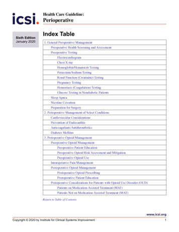
SYSTEMATIC APPROACH TO BEHAVIORAL MODELINGCDNLIVE, MARCH 10, 2015devices and Verilog-A models. The digital simulation enginesimulates netlists of Verilog models, which may be ofindividual logic gates, synthesizable RTL or non-synthesizablebehavioral digital functions.The next step is the Verilog-AMS model, partitioned intoanalog and digital sections. When compiled and elaborated intoa simulate-able database, the model’s behavior is apportionedbetween the digital and analog simulation engines. A certainamount of crossover between simulation engines takes place toallow truly mixed-signal operation.VERILOG-AMS (OR VHDL-AMS)It is Verilog-AMS models which make mixed-signal SOCverification possible with an AMS simulator at the top level.The drawback of AMS modeling is its use of an analogsimulation engine – making it incompatible with SV and UVM.SystemVerilog-AMS and UVM-AMS may be on their way, but fornow, it is RNM modeling with Verilog, VHDL or SystemVerilogthat bridges the gap between analog and digital, and makesmixed signal use of UVM possible and attractive.3. MODELING APPROACHModels are necessary, but it cannot be denied that a bad modelis worse than no model at all. A model may be wrong because ofinitial misunderstanding or because the circuit has changedand the model has not been revised. There’s no completelyautomatic way to generate and update behavioral models, so wepresent a systematic approach which reduces the likelihood ofmodeling errors finding their way into design verification.3.1.USE AUTOMATION WHEN POSSIBLE AND APPROPRIATESchematic, symbol and model views need to be pin-identical.They must have identical pin names and order. This isautomatically checked in the Cadence Virtuoso environment andin similar EDA environments. To automatically create the shellof a model which correctly matches its schematic, (or symbol) Open a schematic (or symbol) of the block to be modeled 2015 XtremeEDA All Rights ReservedPAGE 7
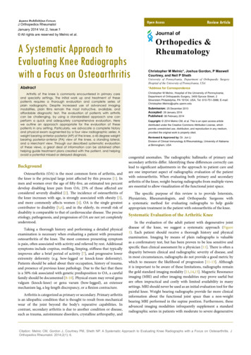
SYSTEMATIC APPROACH TO BEHAVIORAL MODELINGCDNLIVE, MARCH 10, 2015 Automatically create the shell of the model, with I/Omatching the schematic and symbolMake use of “Check and Save” to keep I/O in sync betweenschematic, symbol and modelSee Figure 1Figure 1 Automatically Maintain Schematic, Symbol and Model I/O3.2.COLLABORATE WITH CIRCUIT DESIGNER TO UNDERSTAND THE CIRCUITSTUDY THE SCHEMATICBefore you begin writing model code, get a complete grasp ofthe circuit’s behavior. Study the schematic. Write and sketchyour own interpretation of the circuit. Jot down notes andquestions.3.3.INTERVIEW THE DESIGNERAfter studying the schematic, collaborate with the designer tounderstand the function of every aspect of the circuit.3.4.DEVELOP THE CIRCUIT DESCRIPTIONCreate an accurate, complete, yet concise description ofcircuit functionality. Describe the actual circuit, that is, 2015 XtremeEDA All Rights ReservedPAGE 8
SYSTEMATIC APPROACH TO BEHAVIORAL MODELINGCDNLIVE, MARCH 10, 2015not just the model. Use whatever method best conveys the idea– a list of pins with description, equations, tables ofcharacteristics versus input combinations, drawings.Comment the circuit description into the model file. Some texteditors such as nedit have a rectangular drag-and-drop featuremaking it easy to create diagrams, tables and waveforms out ofASCII characters, as in Figure 2Figure 2 Circuit Description as Comments within Model3.5.CONFIRM THE CIRCUIT DESCRIPTION WITH THE DESIGNERThe designer blesses the description. Neither party shouldtake this lightly. It is a serious two-way commitment. Thedesigner is obligated to inform the model owner regarding anychange to pin-out or behavior. The model owner is obligated tokeep the description up-to-date. Breaking either commitmentendangers the integrity of the model and increases the risk ofsilicon failure.It is a matter of due diligence. There is no foolproof way toforce compliance. A CAD-tool script (e.g. Skill in the case ofCadence EDA tools) may be written to create a sign-off form asa commented text on schematics and symbols. In this approach, 2015 XtremeEDA All Rights ReservedPAGE 9
SYSTEMATIC APPROACH TO BEHAVIORAL MODELINGCDNLIVE, MARCH 10, 2015executing “check-and-save” sends e-mail notices and causesindicators on the schematic and symbol to flash red until themodel owner (and other interested people) sign off that theyhave approved the change. In practice this is only a reminderand sometimes an annoyance. It once again boils down to duediligence.3.6.DECIDE WHICH BEHAVIORS TO INCLUDE IN THE MODELStudy the full-chip verification plan. Understand the role ofthe circuit to be modeled plays in each testcase. Get a feelfor how much detail is required in the model. Interview thelead verification engineer to decide which behaviors of thecircuit must be included in the model and which may beomitted.POSSIBLY OMIT CERTAIN BEHAVIORS FROM MODELFIXED BANDWIDTHThe fixed bandwidth of an amplifier may be well beyond thespectrum of interest for all test scenarios. If so, omittingbandwidth from the model eliminates the solving of adifferential equation, and speeds up model execution.PROGRAMMABLE BANDWIDTHWhat if the bandwidth is digitally programmable? For theapplicable testcases you may want to model that bandwidth. Forothers you may want to use assertions to verify theprogrammability path.ADAPTIVE BANDWIDTHWhat if the bandwidth is digitally controlled by an adaptationalgorithm involving a digital state machine? Here again, thatstate machine may be more thoroughly verified usingconstrained random techniques than with analog signals.POWER SUPPLY SENSITIVITYMisrouting of power supplies is a typical source of error.More so when there are multiple power domains. An obvious 2015 XtremeEDA All Rights ReservedPAGE 10
SYSTEMATIC APPROACH TO BEHAVIORAL MODELINGCDNLIVE, MARCH 10, 2015verification is for each model to monitor and assert theacceptable power supply voltage range. Maybe, especially inthe case of single power supply, you can speed up simulationby treating VDD as a logic signal, and each model monitoringand asserting that VDD is at logic-1 for operation.Standard logic gate models evolved without any sensitivity topower or ground. Nobody thought ahead to a multiple powerdomains, power switching to extend battery life etc. Somepeople took the approach of adding power sensitivity to theirgate libraries. Others developed the concept of Common PowerFormat (CPF).As described elsewhere in this paper, CPF works so well thatyou may consider using it in your analog models. Kind ofironic that a solution for power-ignorance may work betterthan straightforward power-awareness. It’s worth considering,because it’s a net performance gain whenever you can maintaincoverage while simplifying the job of the analog solver.EXAMPLE: DIFFERENT PLL MODELSFORDIFFERENT TESTCASES 2015 XtremeEDA All Rights ReservedPAGE 11
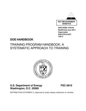
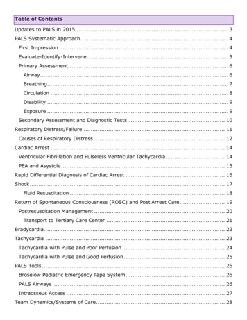
SYSTEMATIC APPROACH TO BEHAVIORAL MODELINGCDNLIVE, MARCH 10, 2015EXAMPLE: DIFFERENT MODEL REPRESENTATIONSOFSETTLING TRANSIENTSFigure 3Realistic versus Simplified Transient ResponsesEXAMPLE: INCLUDINGOROMITTING ANALOG FRONT END 2015 XtremeEDA All Rights ReservedPAGE 12
SYSTEMATIC APPROACH TO BEHAVIORAL MODELINGCDNLIVE, MARCH 10, AFEVGAAFECTFAFECLKA/DDSPDSPFigure 4 Alternative Representations of Analog Front End3.7.CONFIRM THE MODEL PLAN WITH THE DESIGNER AND VERIFICATION LEADThe lead verification engineer and designer bless the plan andit becomes part of the model description, commented within themodel. It is another major commitment from all three partiesto communicate any changes in plans.3.8.WRITE THE MODELWriting the code from the description is comparably easy, ifyou know the modeling languages. Writing model code is noteasy if you don’t know how to do it. Take a course, read thebooks, take part in online forums, get experience. This paperis all about the approach, not the syntax.Here is a partial list of behavioral modeling languages. Modellanguages suitable for SV in UVM are indicated: Verilog-Ao Electrical modeling techniques which conservecurrent and voltage laws for all ports. Electricaloperations, mathematical or logical operations may 2015 XtremeEDA All Rights ReservedPAGE 13
SYSTEMATIC APPROACH TO BEHAVIORAL MODELINGCDNLIVE, MARCH 10, 2015oooobe used internally to the model, but ports must beelectrical. Can be more accurate but may executemore slowly compared to other model types.Analog, and analog representation of digitalRuns on Spectre, SPICE and other device-levelsimulatorsRuns on AMS simulatorsDoes not run on digital-only simulators Verilog-AMSo Electrical, wreal, or logic ports and wireso Electrical modeling techniques conserve current andvoltage laws for analog signals, static biases,references, and power supplieso Real number modeling (RNM) with wreal ports andwires for analog signal flowo Logic ports and internal operationso Runs only on AMS simulatorso Does not run on Spectre, SPICE or other device-levelsimulatorso Does not run on digital-only simulators VHDL-A (Similar to Verilog-A)o Electrical modeling techniques which conservecurrent and voltage laws for all ports. Electricaloperations, mathematical or logical operations maybe used internally to the model, but ports must beelectrical. Can be more accurate but may executemore slowly compared to other model types.o Analog, and analog representation of digitalo Runs on Spectre, SPICE and other device-levelsimulatorso Runs on AMS simulatorso Does not run on digital-only simulatorsVHDL-AMS (Similar to Verilog-AMS)o Electrical, real, or logic ports and wireso Electrical modeling techniques conserve current andvoltage laws for analog signals, static biases,references, and power supplies 2015 XtremeEDA All Rights ReservedPAGE 14
SYSTEMATIC APPROACH TO BEHAVIORAL MODELINGCDNLIVE, MARCH 10, 2015 o Real number modeling (RNM) with real ports and wiresfor analog signal flowo Logic ports and internal operationso Runs only on AMS simulatorso Does not run on Spectre, SPICE or other device-levelsimulatorso Does not run on digital-only simulatorsVerilog (Good for RNM in UVM)o Logic. Only logic ports and wireso RNM with internal real variables and out-of-modulereferences (OOMR) for analog signal flowo Runs on event driven digital-only simulators such asIncisive, VCS, ModelSimo Runs on AMS simulatorso Does not run on Spectre, SPICE or other device-levelsimulatorsVHDLooo(Good for RNM in UVM)Logic and real ports and wiresRNM with real ports and wires for analog signal flowRuns on event driven digital-only simulators such asIncisive, VCS, ModelSimo Runs on AMS simulatorso Does not run on Spectre, SPICE or other device-levelsimulatorsSystemVerilog (Good for RNM in UVM)o Logic and real ports and wireso RNM with real ports and wires for analog signal flowo Verification-centric with random-stimulus emphasiso Object-Orientedo Runs on event driven digital-only simulators such asIncisive, VCS, ModelSimo Runs on AMS simulatorso Does not run on Spectre, SPICE or other device-levelsimulatorsSystemVerilog-AMSo Logico Verification-centric with random-stimulus emphasis 2015 XtremeEDA All Rights ReservedPAGE 15
SYSTEMATIC APPROACH TO BEHAVIORAL MODELINGCDNLIVE, MARCH 10, 2015o Object-Orientedo Electrical modeling techniques which conservecurrent and voltage laws for analog signals andstatic biases, references and power supplies can bethe most accurate but execute more slowlyo RNM with real wires and ports for analog signal flowo Runs on AMS simulatorso Does not run on Spectre, SPICE or other device-levelsimulatorso Does not run on digital-only simulators4. VALIDATING MODELSEvery model must be validated. Validation is typically done ona testbench schematic separate from the full chip environment.It’s not always about matching model simulations to theschematic. For certain testcases you don’t even want a modelto behave like the schematic. The main thing is, you validatethat the model matches the agreed-upon plan.Validation answers two questions:1. Does the model view match its plan?2. Does the model respond to all input scenarios, includingbad logic and illegal combinations?In the ideally best practice the model be validated by someoneother than its author, but the analog designer shouldn't haveto learn Verilog-AMS or even how to run the AMS simulator todo so. Here is an approach that is a workable compromise:4.1.DOES THE MODEL VIEW MATCH ITS PLAN?1. Model designer creates a testbench schematic whichinstantiates and connects symbols for the device undertest (DUT) and a driver-monitor (DMON)2. Circuit and model designers collaborate to describeanalog and digital stimulus3. Model designer creates DMON stimulus, simulates theschematic, and simulates the model4. Debug until the model simulation is correct. That is, sothat it matches either the schematic simulation or 2015 XtremeEDA All Rights ReservedPAGE 16
SYSTEMATIC APPROACH TO BEHAVIORAL MODELINGCDNLIVE, MARCH 10, 2015conforms to the planned response, where different fromthe physical circuit5. Model designer delivers a turnkey simulation scenario tothe circuit designer. This could be a Cadence “analogartist” state for instance, which is comfortable for thecircuit designer to execute and examine6. Circuit designer reruns the simulation in a familiarenvironment, and “blesses” the model and its stimulus andresponse4.2.DOES THE MODEL RESPOND TO ALL INPUT SCENARIOS, INCLUDING BAD LOGICAND ILLEGAL COMBINATIONS?In the course of full chip testcases the model may receiveunexpected input. When this happens it is very important thatthe model not cause the simulator to crash. Worse than thatwould be if the model were to ignore the faulty input and goon as if all is well. For example, passing signals whenthere’s no power supply, or when the power-down input is inthe unknown state.Unfortunately there are infinite combinations of no-good inputcontrols and analog waveforms. So the model designer does hisbest to come up with a good enough set to try out all themodel's fault detecting code (i.e. assertions). The designengineer and lead verification engineer may critique andrequest other input sequences. This part of validation is veryimportant and tends to reduce the number of problems occurringin full chip simulation. It is based on experience andintuition.1.2.3.4.Use constrained random approach where possibleInclude out-of-range analogInclude illegal combinations of logicInclude unknown ‘x’ statesThe point is to ensure the model doesn’t “pretend” everythingis okay, or hang the simulator when something goes wrong.5. MODELS AND APPLICATIONSDifferent platforms require different levels of models toreach the verification goals of the system. 2015 XtremeEDA All Rights ReservedPAGE 17
SYSTEMATIC APPROACH TO BEHAVIORAL MODELINGCDNLIVE, MARCH 10, 2015Analog requirements traditionally have been about meeting thespecification performance parameters while taking into accountsystem parasitics and error sources to make sure operation ofindividual circuits and the full system are met across cornersand statistical variations.Digital design was traditionally verified based on the usemodel understanding of the design and verification teams. Theverification effort was easily accomplished by a series oftests that verified different paths of the design (directedtests). With increased complexity and a higher user pool thisuse-model was proven to be limited and new testing methodswere developed. From constrained-random, OVM, UVM, etc. testcoverage has improved dramatically to predict different usemodel scenarios resulting in higher verification success.5.1.ANALOG VERIFICATIONPure Analog test benches are setup quickly by using librarycomponents that allows the engineer to set voltages, currents,resistances, etc. that drive and/or load the DUT. Complexstimulus blocks are modeled using an AHDL language such asVerilogA.With higher complexity and digital integration mixed-signalverification tools may be required. Many Analog engineersavoid this due to issues with interface elements (or connectmodules) and the extra effort to setup configuration files andcorrect stop views. Digital blocks are then, many times,modeled using VerilogA. This provides a very successful analogverification methodology but obviously has issues if thedigital block and VerilogA model do not match.ANALOG MIXED-SIGNAL SIMULATIONSAnalog Mixed-Signal (AMS) Engineers are capable of bridgingthis gap in verification. Most of these engineers understandthe complexity of analog circuits and have a solid backgroundwith digital RTL, behavioral and gate level circuits.Many simulations with Big-A and Little-D (mostly Analog withminimum digital blocks) can be fully verified with this typeof platform. By using fast simulators such as APS-AMS, 2015 XtremeEDA All Rights ReservedPAGE 18
SYSTEMATIC APPROACH TO BEHAVIORAL MODELINGCDNLIVE, MARCH 10, 2015Ultrasim-AMS, Spectre XPS MS and setting the proper simulationprecision for each block the system can be simulated quicklyand precisely.Timing interfaces, calibration circuits, etc. could be coveredwith a limited set of tests that checks the importantinterface components and system performance parameters. Thepredictability of how the system is used allows for this typeof verification to be sufficient.DIGITAL SIMULATIONS WITH AMS MODELSWith advances in technology and smaller feature sizes moreintegration is available in an IC. Full SOC’s are nowintegrated with different IP’s including Analog IP.Creating tests that cover the use-space of the IP is now adaunting task that makes it very difficult to be covered in aslow simulation environment. SOC simulations typically run formicroseconds, milliseconds and higher while analog simulationis limited due to the required time and resources.In such a system the Analog and Mixed-Signal verificationmethods mentioned previously still applies but it is alsonecessary to add another level of verification that can beused by the SOC integration and verification teams to makesure the system works in multiple use-model scenarios and inreasonable time.For small SOC’s the Analog can be modeled using mixed-signallanguages, such as Verilog-AMS or VHDL-AMS, and integratedinto the digital verification platform. This is much slowerthan a digital only simulation, therefore, the number ofsimulations used in this scenario should be limited to a setof tests that provide enough code and functional coverage forthe system.5.2.DIGITAL VERIFICATIONFor large SOC’s UVM allows highly complex systems to beverified due to the comprehensive testing included in themethodology. This includes integration of Analog IP as part ofthe SOC and verification plan. 2015 XtremeEDA All Rights ReservedPAGE 19
SYSTEMATIC APPROACH TO BEHAVIORAL MODELINGCDNLIVE, MARCH 10, 2015To test the analog, SOC design and verification teams maydevelop a model of the analog system based on thespecifications and its description of the analog subsystem.Digital engineer’s knowledge of analog systems may be limitedso the model may just be a code-coverage model to make suresignals are arriving at its destination. It is then the AnalogEngineer’s responsibility to verify the block under all thedifferent conditions.Many issues have been found with this type of verificationapproach which results in endless hours of root-causeanalysis. Typical issues with this approach includespecifications that are not up to date, uncommunicated analogblock changes, misunderstanding of timing constraints orrequirements, polarity changes, hierarchical differences inthe model vs actual circuit, etc.From a digital verification perspective the verificationmetrics may be meeting the intended goals but is not capableof capturing all the issues mentioned above. From the Analogside all the required simulations have been completed anddetermined to be functional.As mentioned previously then it is of essence to developmodels and a methodology that can accomplish the fullve
including Verilog or System Verilog using real number modeling (RNM), Verilog-AMS (including WREAL), and Verilog-A. And for models intended for UVM, Verilog, or Verilog-AMS simulation platforms. Between them, the authors have more than 40 years’ behavioral