Transcription
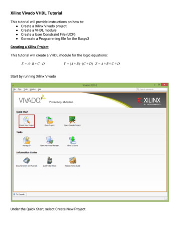
Xilinx Vivado VHDL TutorialThis tutorial will provide instructions on how to: Create a Xilinx Vivado project Create a VHDL module Create a User Constraint File (UCF) Generate a Programming file for the Basys3Creating a Xilinx ProjectThis tutorial will create a VHDL module for the logic equations:X A B C DY (A B) (C D) Z A B C DStart by running Xilinx VivadoUnder the Quick Start, select Create New Project
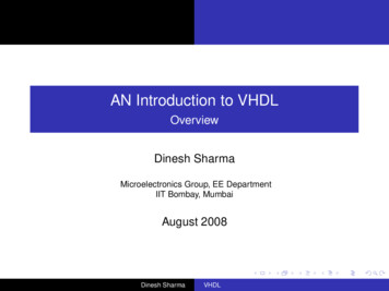
This brings up a series of dialog boxes to step you through the process of creating a project. ClickNext to create a project name and save location. When picking a name and location do not use anyspaces. (ie use “MyProject” or “My Project” instead of “My Project”) I would recommend selectingCreate project subdirectory. That will automatically create a folder with your project name in yourproject locationClicking Next will bring up project type options. The projects we create for this course will be RTLProjects. Select RTL Project and click next.
The next 3 dialogue boxes are for adding Sources, Existing IP, and Constraints. We will add thosesource files later, so you can just click next for each of them.The next dialogue has options to select the type of device we will be programming. For our project,we will be targeting the Atrix7 in the Basys3 board. It is important you select the following options onthis dialog:FamilyAtrix-7Packagecpg236Speed Grade-1Partxc7a35tcpg236-1Clicking Next will give a Project Summary of the options selected. If any of the options need to becorrected, you can click Back and make any of the necessary changes. Once you verify all of theoptions are corrected, click Finish
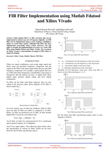
Vivador InterfaceThe new project will be opened in Vivado. Only 1 project can be open at a time, so opening a differentproject will automatically close the current one. The Vivado interface is shown below.There are 4 main sections to the Project Navigator interface:1. Flow Navigator: List of all available processes that can be run in the current project and theircurrent state if running.2. Sources Window: This is where all of the source files for the project are listed.3. Editor Window: Display of the current file being edited. If no source file is selected, it defaultsto a project summary page4. Console Panel: Display of all status messages. This is an important window to look at forwarning and error messages
Adding A Source FileTo add a source file to the project, select Add Sources in the Flow Navigator.This will open an add source dialogue box. To add a VHDL Module, select Add or Create DesignSources.
Clicking next will bring up a similar Add or Create Design Sources that we skipped over when creatingthe project. A source file could have been created when first creating the project using the sameprocess as detailed below.Click on the green icon. A previously created VHDL modules could be added to the project byclicking Add Files. To create a new module, click Create FileSelect File type as VHDL. You can enter any File name for the module, but it is recommended to notuse any spaces. Click OK
This returns to the Add or Create Design Sources so multiple modules can be added at the sametime.After all of the wanted sources have been added, click Finish. This will bring up a Define Moduledialogue box to create a framework for each of the VHDL modules. With this dialogue, each modulecan have the inputs and outputs defined. For this project, A, B, C, and D are inputs (in) and X, Y, and Zare outputs (out).After all of the inputs and outputs are defined, click OK to return to Vivado
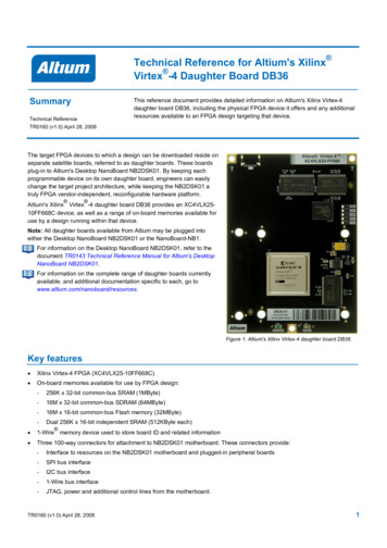
VHDL EditorThe added VHDL module will show up in the Source window. Double clicking on the module name inthe Source window will open the file in the editor window. To make editing easier, the editor maximizebutton will cause the editor window to fill the Vivado application.
Looking at the editor window, the module has been created with all of the inputs and outputs definedAdd the necessary VHDL code for the logic circuits wanted. The added code will go after the beginand before the end Behavioral;X A B C DY (A B) (C D) Z A B C D
The design can now be synthesized and simulated (refer to the ISim tutorial). To create aprogramming file to be loaded onto the FPGA, we will need to add another source file.Constraint FileThe Constraints file will tell the FPGA where to connect the inputs and outputs of your logic circuit tothe development board. In this example the inputs A, B, C, and D will be connected to switches on theBasys3, SW0, SW1, SW2, and SW3 respectively. The outputs X, Y, and Z will be connected to the LEDSLD0, LD1, and LD2.Any circuit input can be connected to any input on the FPGA development board, although multipleinputs cannot be connected to the same component. In the same way, multiple outputs cannot beconnected to the same device on the development board.Add a new source file as before, selecting “Add or Create Constraints File” from the Add Sourcesdialogue this time and click Next
Just as before with the VHDL module, a previously created constraints file could be added to theproject by clicking Add Files. To create a new file, click Create FileSelect a file type of XDC. You can enter any File name for the module, but it is recommended to notuse any spaces. Notice the File location for saving the new file is in the current project folder. ClickOKThis returns to the Add or Create Constraints so multiple files can be added at the same time. Only 1file is needed for this example, so click Finish
The added constraints file will show up in the Source window. Double clicking on the constraints filename in the Source window will open the file in the editor window. To make editing easier, the editormaximize button will cause the editor window to fill the Vivado screen. The constraints file will showup as a blank file.
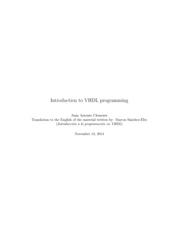
Each input and output being connected requires 2 lines in the XDC file. The format the XDC file is:set property PACKAGE PIN Port Number [get ports { Net Label}]set property IOSTANDARD LVCMOS33 [get ports { Net Label}]Where Net Label is the label given for the input or output in the VHDL module and Port Number is theport address connected to the development board device. These port addresses can all be found inthe reference manual for the development board. In this example, we will use the followingconnections on a Basys3 development board.I/ODevicePort NumberASwitch 0 (SW0)V17BSwitch 1 (SW1)V16CSwitch 2 (SW2)W16DSwitch 3 (SW3)W17XLED 0 (LD0)U16YLED 1 (LD1)E19ZLED 2 (LD2)U19The finished XDC file would look like:set property PACKAGE PIN V17 [get ports { A}]set property IOSTANDARD LVCMOS33 [get ports { A}]set property PACKAGE PIN V16 [get ports { B}]set property IOSTANDARD LVCMOS33 [get ports { B}]set property PACKAGE PIN W16 [get ports { C}]set property IOSTANDARD LVCMOS33 [get ports { C}]set property PACKAGE PIN W17 [get ports { D}]set property IOSTANDARD LVCMOS33 [get ports { D}]set property PACKAGE PIN U16 [get ports { X}]set property IOSTANDARD LVCMOS33 [get ports { X}]set property PACKAGE PIN E19 [get ports { Y}]set property IOSTANDARD LVCMOS33 [get ports { Y}]set property PACKAGE PIN U19 [get ports { Z}]set property IOSTANDARD LVCMOS33 [get ports { Z}]
Spacing is important! Make sure to use a single space between get ports and {} and no space inside {}Programming File GenerationWe can now create a programming file to load on our Basys3 development board. The Flow Navigatorpanel lists the processes in order that need to be run to create a programing file.1. Run Synthesis2. Run Implementation3. Generate BitstreamEach process can be run individually by double clicking on them or right clicking and selectingLaunch. If you double click on a process that requires a previous process that has not already beenrun, the prerequisite processes will be run automatically.If the Generate Programming File process finishes without error, it will create a .bit file you can use toprogram the development board. Programming the board can be accomplished with Digilent Adept. Ifthere are any errors in the process, they will show up in the Messages Tab of the Console Panel.The created bit file is saved in the project folder under ProjectName.runs/impl 1/ModuleName.bit
VHDL Editor The added VHDL module will show up in the Source window. Double clicking on the module name in the Source window will open the file in the editor window. To make editing easier, the editor maximize button wil