Transcription
University of TwenteFaculty of Electrical Engineering,Mathematics and Computer ScienceVHDL tutorialFor internal use only E. MolenkampJanuary 2016
Contents12Introduction . 3Simulation with ModelSim . 42.1Analyse/Compile . 52.2Simulate. 72.2.1 Script file with the stimuli . 102.2.2 Stimuli generation with VHDL . 102.3Simulation model . 153Synthesis with Quartus II . 163.1Start Quartus II . 173.2Create a new project . 173.3Top level of the design . 213.4Compile ( synthesize). 213.5RTL viewer/Technology Map Viewer . 224Post simulation . 235Constraint file . 266Programming the device. 277Synthesis with Precision RTL . 28Appendix A An alternative description for count . 31Appendix BVerification of a design via simulation. 32Appendix CModelSim/QuestaSim if no project is used . 34Appendix D Compiling Altera libraries with QuestaSim . 35Appendix EProgramming Cyclone II (DE1) . 36Appendix FProgramming Cyclone V (DE1-SoC) . 37Appendix G Datasheet Report. 402
1 IntroductionVHDL is the hardware description language used in this course. It is one of the languagesused in many companies in Europe. Many tools are available for simulation and synthesis. Wehave chosen a toolset that can also be installed at home (no license required).VHDL simulationModelSim-Altera StarterIncludes post simulationlibraries for Altera devices.(Windows/Linux)HomeX(Optimization is disabled inthe free version.)QuestaSimInstalled on the lab machinesand supports PSL.VHDL SynthesisFor post simulation of a designthe vendor libraries should becompiled first.Quartus IIQuartus II web edition(free)(windows/linux)Precision RTLIs a technology independentsynthesis tool.UniversityX(windows)XXXX(windows)XTable 1: tools used in the load/altera design/quartus we/dnl-quartus we.jspNotes:1. The free web editions of the Quartus II software support only the latest devices of a familye.g. If you use a “Cyclone I” device use version 11.0 SP1. If you use a “Cyclone II” device use version 13.0 SP1. This device is used in thepopular DE1 development board. If you use a “Cyclone V” device use version 14.0, 15.0(post simulation with timing is not for Cyclone V devices. The *.sdo file is not createdonly a functional post simulation is possible (file *.vho).2. The interface of the different versions may slightly be different.3
2 Simulation with ModelSimIn this tutorial a circuit is used that counts the number of ones in the input 18.19.20.21.LIBRARY ieee;USE ieee.std logic 1164.ALL;ENTITY count ISGENERIC (w : positive : 8);PORT (a : IN std logic vector(w-1 DOWNTO 0);q : OUT integer RANGE 0 TO w);END count;ARCHITECTURE behaviour OF count ISFUNCTION cnt (a:std logic vector) RETURN integer ISVARIABLE nmb : INTEGER RANGE 0 TO a'LENGTH;BEGINnmb : 0;FOR i IN a'RANGE LOOPIF a(i) '1' THEN nmb: nmb 1; END IF;END LOOP;RETURN nmb;END cnt;BEGINq cnt(a);END behaviour;Figure 1: behavioural description of count (the line numbers are not part off the VHDL code!)Generic w, line 4, is a global constant with value 8. Input a of this design is w bits wide. Theoutput q is an integer value. The width of the input is w, therefore the number of ones must bebetween 0 and w (inclusive). A range constraint is added to the integer type. The rangeconstraint is not necessary but it is used for documentation and will guide the synthesisprocess.There are many ways to count the number of ones in an array. In the architecture (figure 1) afunction is declared that takes care of this. This function has as input an object of typestd logic vector. A std logic vector is an unconstrained array; the length of this type is not(yet) known! The reason to use an unconstrained array as input is to make the design genericwith respect to the width of the input. At the location of the function call, line 20, the range ofthe input is known.The algorithm used in the function is straightforward. With a loop statement all elements ofthe inputs are examined. The only problem is: what are the vector indices? The attribute'range is used for this. If the function is called with an object that is declared asstd logic vector(5 to 36) then within the function the a'range is replaced with 5 to 36.This design is simulated using ModelSim.4
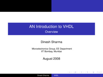
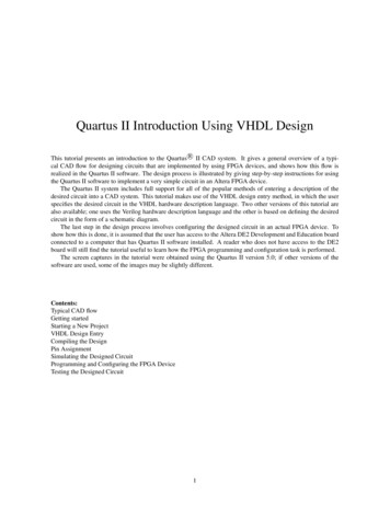
2.1 Analyse/Compilefigure 2: ModelSim screenModelSim starts with the window shown in figure 2. In this tutorial a project is used. So wewill first create a project:File New ProjectChoose a “project name” and “Project location”. Do not change the default library name‘work’ and also select the option “copy library mappings”.5
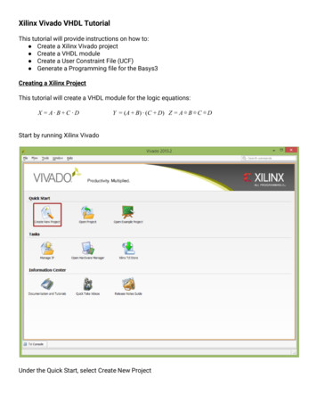
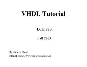
Select “add existing file” and browse to the directory with the source file and select the file“count.vhd”.Click on OKand close the “add items to the Project”Right-click on the file “count.vhd” compile compile selectedThe design is compiled into library work. You can verify this by clicking the tab libraryFigure 3: the result after compilationThe top window shows the libraries and the bottom window (“Transcript”) is used forcommands entered by the user and for reporting information to the user. You can dock (as6
shown above) and undock (a separate window) using the arrow in the upper right corner of awindow.By default an analysed VHDL design is stored in a library work.Notes1 The content of the library work is managed by ModelSim. Do not change thecontents of this library outside ModelSim nor place your source files in thatlibrary!2 If you want to delete a compiled design from the library right click the design (tablibrary should be selected) in the GUI and select delete. Your source file is still in theproject.3 If you want to remove a file from the project right click the file (tab project should beselected) in the GUI and select remove from project.Important: if the file was compiled then the design units that were in the file are notremoved from the library!4 ModelSim uses the term Compile instead of Analysis.5 For the VHDL object signal ModelSim uses also the term object.6 For the VHDL object variable ModelSim uses also the term local. During debuggingof a design locals are not visible by default. This can be changed:tab View select “locals”.2.2 SimulateClick with the right mouse button on the architecture name ‘behaviour’ and you can load yourdesign in the simulator (or you can use menu simulate start simulation).Figure 3a: Selection of the design that should be simulated7
Note:In the ModelSim-Altera starter edition “Enable optimization” is disabled. In case alicenced version of ModelSim/QuestaSim is used optimizations it is on by default.Optimization improves simulation speed but during debugging not all signals andvariables are visible. Therefore select ‘full visibility’ in the tab OptimizationOptions.Select the design and click OKDuring simulation you probably like to see some waveforms therefore enter:add wave * return (In stead of * you may enter a list with the signal names separated with a comma).Notes1. If the signals a and q are not shown in the window wave you probably did not selectcount in the window instance. Select count and repeat the command “add wave *”2. The windows objects and locals show respectively the signals and variables that arevisible at the selected instance. Select line 20 and you will also see the generic w.3. You can also drag and drop objects and locals to the wave window.Figure 3b: Selection of the design that should be simulated8
With the run command you perform a simulation:run 200 ns enter Why are the input values ‘U’?With the force command you can apply an input pattern to a:force a 'b01100011 enter 1run 100 ns enter Try it with some other values for a.You can assign multiple values to the input with:force a 'b11111111, 'b00111111 10 ns, 'b11110101 20 ns enter run 100 ns enter Try it.Note:In VHDL descriptions a space is required between the number and the time unit. So“100ns” is not correct, it must be but “100 ns”. ModelSim will report a warning:Warning: [4] path . file ( line number ): (vcom-1207) An abstract literal andan identifier must have a separator between them.It is probably only a warning because the examples in the first VHDL standard (1987)did not have the spaces .The user interface of ModelSim supports both.1The default radix depends on de version of ModelSim/QuestaSim. In the past it was binary. E.g.force a 01100011 is the binary pattern 01100011. As of QuestaSim version “Sim-64-10.2” this the default ischanged to hexadecimal. So 01100011 is hexadecimal and equal to binary 100010000000000000001001 and thelowest 8 bits are assigned to input a. Explicitly add a radix avoids confusion, e.g.force a 'b1110 for binaryforce a 'hDfor hexadecimalforce a 'd14for decimal9
Notes:1. If the wave window is selected you can zoom in and out with the buttons:- zoom in- zoom out- zoom full- zoom in on active cursor. (Select a point in the wave window and a cursor appears.)2. Multiple cursors are possible in the wave window. Right-click the bottom black line inthe wave window. The time differences between the cursors are also shown.2.2.1 Script file with the stimuliA tool dependent solution to apply stimuli is using a script file. A simple example is givenbeneath. Create a file “demo.do” with the following contents:force a 'b00011111run 100 nsforce a 'b10100000run 100 nsIn ModelSim this script file is executed with the command:do demo.do return Notes1A synchronous design has a clock. Assume signal clk is the clock. A repetitive patternis created with the command:force clk 0, 1 50 ns -repeat 100 ns(DO NOT copy from the pdf file because characters look the same, but may bedifferent)(this can also be used for other signals, not necessarily a clock.)2The ModelSim command “run -all” starts a simulation and will stop when no eventsare scheduled for the future. Do not use this command when a clock signal isgenerated with the method described in Note 1. Why not?3Commands that are entered in the transcript window can be written to a file with thecommand “write transcript filename ”. This file can be used as a script fileafterwards.2.2.2 Stimuli generation with VHDLApplying stimuli as presented in the previous section is tool dependent. It is also possible, andstrongly advised to be tool independent, to generate stimuli using VHDL.Finding test data for a design is not an easy task. In this example an exhaustive test is usedwhen the width of the data vector is not too large.LIBRARY ieee;USE ieee.std logic 1164.ALL;USE ieee.numeric std.ALL;ENTITY testset ISGENERIC (w : positive : 8);10
PORT (data : OUT std logic vector(w-1 DOWNTO 0));END testset;ARCHITECTURE set1 OF testset ISBEGINPROCESSBEGINdata (others '0');-- all zeroWAIT FOR 10 ns;data (others '1');WAIT FOR 10 ns;-- all oneFOR i IN 0 to 2**w-1 LOOPdata std logic vector(to unsigned(i,w));EXIT WHEN i 20; -- an exhaustive test is not performed if w is largeWAIT FOR 10 ns;END LOOP;WAIT; -- foreverEND PROCESS;END set1;Figure 4: simple test set.Figure 4 shows a simple test set. It contains one process statement. It first generates all zeros,waits for 10 ns, then it generates all ones and it waits again. Of course an exhaustive test ispossible. In the for-statement the loop parameter i (which is implicitly declared!) goes from 0to 2w-1. This integer value is converted to a bit pattern (using binary coding; also calledunsigned). For the conversion the function to unsigned is used. This function converts theinteger value i to an unsigned vector with length w. This function is located in a packagenumeric std (this package is in library ieee). However in case the generic ( constant) w islarge this is a time consuming task. Therefore in this example the loop is ended in case i isequal to 20. The process ends with wait. This means the process will not resume execution.Background information: numeric stdThe package numeric std declares two types:- signed (twos complement representation) and- unsigned (binary representation).Both types are similar to type std logic vector; arrays with elements of type std logicvariable sa,sb,sc : signed(2 downto 0);variable ua,ub,uc : unsigned(2 downto 0);variable a,b,c : std logic vector(2 downto 0);If sa is “111” then it is interpreted as -1 (twos complement).If ua is “111” then it is interpreted as 7.Is a is “111” then no number interpretation is associated with it!What is the result of the statement: sa : sb “11” ?The operands do not have the same length. Since sb is of type signed the shortest vector issign extended before the addition takes places.In case the operands are of type unsigned the shortest vector is extended with zeros.In case the operands are of type std logic vector you cannot perform an addition because nonumber interpretation is associated with this type.VHDL is a strongly typed language therefore you can not write:a : sa;However the types are closely related. In that case a type conversion function can be used:a : std logic vector(sa);11
If you want the integer value of a vector you simply write:integer value : to integer(sa);If you want to convert an integer to a vector you must add the length of the vector:sa : to signed(integer value,3) orus : to unsigned(integer value,us'LENGTH)The attribute LENGTH is used in the last example.2.2.2.1 Add a design unit to the projectIf the simulator is still active, end the current simulation via the simulate menu.Perform the following steps to add testset.vhd to the project1. Be sure the tab project is selected.2. Right click in the project window.3. Add to project Existing file4. Click on OKCompile the design and perform a simulation. Since the design entity testset ends with a waitstatement when all test patterns are applied you can use the command:run –all enter 12
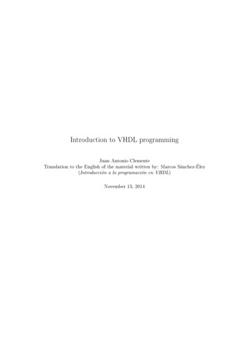
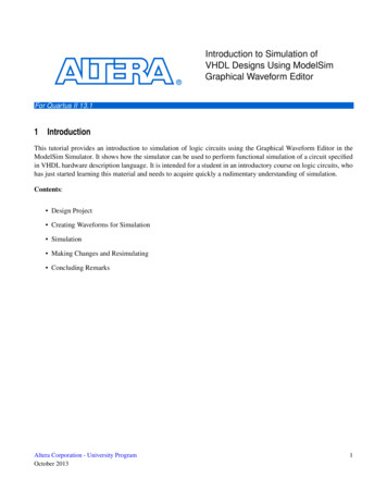
Figure 5: simulation result of the test set2.2.2.2 Connect the test set with the design under testFigure 6 shows the structural VHDL description that connects the design entity testset withdesign entity count. Add the file testbench.vhd to the project and simulate entity testbench.Check that the length of the pattern is changed to 10 in the design (figure 6)!LIBRARY ieee;USE ieee.std logic 1164.ALL;USE ieee.numeric std.ALL;ENTITY testbench ISGENERIC (width : positive : 10);END testbench;ARCHITECTURE structure OF testbench ISCOMPONENT testsetGENERIC (w : positive : 8);PORT (data : OUT std logic vector(w-1 DOWNTO 0));END COMPONENT;COMPONENT countGENERIC (w : positive : 8);PORT (a : IN std logic vector(w-1 DOWNTO 0);q : OUT integer RANGE 0 TO w);END COMPONENT;-- local connectionsSIGNAL stimuli : std logic vector(width-1 DOWNTO 0);SIGNAL output : integer;BEGINts : testsetGENERIC MAP (w width)PORT MAP ( data stimuli);dut : countGENERIC MAP (w width)PORT MAP ( a stimuli,q output);END structure;Figure 6: test bench13
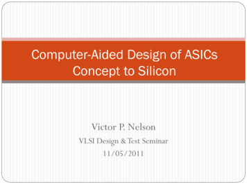
Figure 7: The design hierarchy is shown in the upper left windowWith these buttons you can step through your design (e.g. to locate errors). The ‘step’ buttonis often used. Then only one statement (concurrent or sequential) is executed. Also asource window is opened so you can see (the arrow) what the next statement to be executed.“Step -Over”is similar to the execution of a function/procedure in one step.During debugging you often like to run your program to a certain point and perform a lowlevel debugging from that point. Double click on the right of the line number of an executableline and a breakpoint appears.Figure 8:Simulation result14
2.3 Simulation modelVHDL is a collection of concurrent statements. The order of the concurrent statements has noeffect on the behaviour.Concurrent statements can only communicate with each other using signals2. If you assign avalue to a signal that signal value is not updated immediately. This means that all processeswill use the same signal values; consequently the simulation is order independent w.r.tconcurrent statements. If you assign a value to a variable that variable is updated immediately.Users who are not that familiar with VHDL are often surprised by this update mechanism andthe consequence it has for simulation and synthesis.If you write:y a after 10 ns;The output y follows the input a with a delay of 10 ns. (More precise the signal a must bestable for 10 ns too.)If you write:y a;The output is updated after a delta delay. Delta delays are not shown in the wave window.There can be an infinite number of delta delays before simulation time advances. ModelSimwill report a warning when it has executed 1000 delta steps.ModelSim can show the result of signals after a delta step. Repeat the previous simulation but(also) use the following command:add list * return Check that you really understand what is going on.2You can use a “shared variable” but that is not part of this tutorial since the simulation result is tool dependentand synthesis tools do not support this.15
3 Synthesis with Quartus IIWith Quartus II a VHDL description is synthesized for Altera devices.Notes1Although not required for VHDL it is advised that the name of the file is the same ofthe name of the entity.2In the VHDL description the pin locations of inputs and outputs are not specified(although it is possible).3Most synthesis tools do not handle the sensitivity list correctly. The synthesis toolassumes that the sensitivity list includes all signals read in the process. A mismatchbetween simulation and synthesis can occur if the concurrent statement does not modelsynchronous hardware.ModelSim has an option that checks the sensitivity list at compile time. Right click thefile count.vhd in the project. Select VHDL and mark “check for Synthesis”.The constraint file (with the file extension qsf) should be in the project directory. Theconstraint file contains the pin locations of the input and output signals. If no constraint file isadded the software will assign random pin locations to the inputs and outputs. For now wewill skip the constraint file (see chapter 5).16
3.1 Start Quartus IIIf you have a constraint file (file extension is qsf) it should be in the project directorybefore you start Quartus II.3.2 Create a new projectFile New Project WizardSkip the Introduction NextBrowse to your project directory use as name for the project: countClick Next17
Select the file(s) you want to include: count.vhd. Don’t forget to click on the add buttonafterwards!Click NextSelect the device that is on the board.18
NoteIf it is not the intention to program a device, you can select any device.Click Next.Simulation Tool name: ModelSim-Altera and Format: VHDLThis allows post simulation of the design. This will be discussed in chapter 4.“Next”Finish.19
20
3.3 Top level of the designA design often has multiple design files. The top level of a design is the same as the name ofthe Quartus II project. In this tutorial it is count.The picture above is from another designWith the mouse right click on the file that contains the top level of the design. Now you canchange the top level design.3.4 Compile ( synthesize)Processing Start CompilationNote1. Only a subset of VHDL is synthesizable therefore it is possible that Quartus II, andother synthesis tools, generate error messages!2. Synthesis tools generate many warnings! For some warnings you should be aqualified user! (we assume you are a novice user.)21
3.5 RTL viewer/Technology Map ViewerAfter synthesis a schematic can be generated:- RTL view; this view is very close to the VHDL description.- Technology view is an optimized result for the given technology.Tools Netlist Viewers RTL ViewerTools Netlist Viewers Technology Map Viewer (post-mapping)Notice that the loop structure in the VHDL description is visible in the RTL view whereas inthe Technology Map view it is realized with an efficient tree like implementation.22
4 Post simulationThe free ModelSim-Altera includes compiled versions of the Altera libraries that are requiredfor post simulation. For the licensed version QuestaSim the Altera libraries have to becompiled first. For more information see page 35.After synthesis a post simulation can be performed with the real delays (as expected byQuartus II for the device). During simulation several constraints are checked, e.g. setup andhold times violations.Notes 1:The DE1-SoC kit has as device a Cyclone V “5CSEMA5F31C6”. Quartus does not supportpost simulation with timing (*.vho and *.sdo files). Functional post simulation (withouttiming) is possible (*.vho file).The EDA netlist writer will report “Warning (10905): Generated the EDA functionalsimulation files although EDA timing simulation option is chosen.”The *.sdo file is notgenerated.In the project directory the following directory is created: project directory \simulation\modelsimIn this directory there are the files:- count.vho (VHDL output file)- count vhd.sdo (standard delay output file) (not for a Cyclone V device)Notes:1. The names and extensions of these files depend on the synthesis tool.2. The DE1-SoC kit has as device a Cyclone V “5CSEMA5F31C6”.A fragment of the generated VHDL file is (Quartus II version 15.0):--- This VHDL file should be used for ModelSim-Altera (VHDL) only-LIBRARY ALTERA LNSIM;LIBRARY CYCLONEV;LIBRARY IEEE;USE ALTERA LNSIM.ALTERA LNSIM COMPONENTS.ALL;USE CYCLONEV.CYCLONEV COMPONENTS.ALL;USE IEEE.STD LOGIC 1164.ALL;USE IEEE.STD LOGIC ARITH.ALL;ENTITY count ISPORT (a : IN std logic vector(7 DOWNTO 0);q : OUT STD.STANDARD.integer range 0 TO 8);END count;23
Note:1. The port declaration of the generated post simulation model is tool dependent. Quartusversion older than version 11 used types std logic and std logic vector. E.g.ENTITY count ISPORT (a : IN std logic vector(7 DOWNTO 0);q : OUT std logic vector(3 DOWNTO 0));END count;This is closely related to the realization (4 pins are used for the integer range 0 to 8). Adisadvantage is that if the generated post simulation modeled is verified using thetestbench the mismatch between the types used in the component instantiation andthose in the generated entity declaration will raise an error: some rewriting isnecessary. Advanced users probably use type conversion functions in the port map.Often one of the guidelines in a company is that you must use std logic andstd logic vector at the top level entity. Then you never have a mismatch because allsynthesis tools will use these types also in the generated post simulation model.To perform a post simulation:1. Add the file project directory \simulation\modelsim\count.vho to the project.2. Compile file count.vho3. simulate start simulationSteps in red not necessary if *.sdo file is not generated (e.g. for Cyclone V device)a. Tab design:Select your design count(structure) and set the resolution to “ps” (The delaysin the SDF files is in pico seconds).b. Tab SDFSelect file project directory \simulation\modelsim\count vhd.sdo (via ADD)4. Perform a simulation.In case *.sdo file is not generated a functional post simulation is performed (no delay)24
Notes:1. You can also apply a region when the SDF file is selected. This is required in casethe synthesized design is part of a larger system (e.g. a component instantiation).The path to the component is the region (e.g. if it is instantiated in the top-levelarchitecture the label of the component instantiation that is used).2. The default run length in ModelSim-Altera is 100 ps. The default run length can beany other value. Therefore explicit add the time unit in a script file; e.g. “run 100ns” instead of “run 100”.25
5 Constraint fileIn the top-level entity description the input and output ports are enumerated. However thephysical pin to which a port is connected has to be specified. This can be done in a constraintfile.An example of a constraint file for Quartus II is:set location assignment PIN E16 -to q[0]set location assignment PIN G14 -to q[1] Fragment of the constraint file count.qsfFor Quartus II the name of the constraint file should be the same as the name of the top-levelentity. The file should be located in the project directory.Notes1. During synthesis Quartus II will change the contents of the qsf file. Yourconstraint file should be in the project directory before you start Quartus II.2. Precision RTL (see page 28), and other tools, often use the SDC (Synopsys DesignConstraint) file also for the pin mapping. Precision RTL requires that the SDC fileis explicitly included. The syntax is a little bit different:set attribute -name pin number -value E16 -port q(0)set attribute -name pin number -value G14 -port q(1)3. Quartus II uses the SDC file for timing constraints. E.g. if a synchronous designhas a clock with name clk and it operates at 100 MHz. This information is placedin the synopsys design constraint file: top level design name .sdccreate clock -period 10.000 -name clk [get ports clk]26
6 Programming the deviceIt depends on the development board used. See appendix for the DE1 development board andDE1-SoC development board.27
7 Synthesis with Precision RTLPrecision RTL is a technology independent synthesis tool. It can be used on top of Quartus II(for Altera devices), or ISE (for Xilinx devices), and more. It also can perform retiming:moving flip-flops in the design to increase the maximum clock frequency. For our coursePrecision RTL is not needed. However the tool generates an RTL schematic very quickly!Start Precision RTL.Figure 8: Precision start up screenClick on “New Project” and browse to the folder that contains the source files (filecount.vhd).) (choose a project name, and create impl(ementation) should be selected(default)).Figure 9: Precision “Design” tabSetup Design (target device)Click “Setup Design” and select device, e.g.28
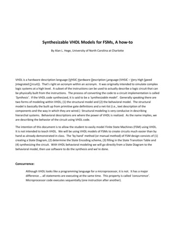
Click OK.Input filesClick “Add Input Files”.NoteThe order is not important. The tool automatically reorders the files.Select the design files and press OK.Compile the designPress the compile button.The tab “Design analysis” is added at the lower left corner.Select this tab, and choose “View RTL Schematic” (figure 10).29
Figure 10: schematic view of the designThe compile step is an intermediate step (still technology independent).Tab Design Synthesis will map the intermediate result to the chosen technology.Figure 11: schematic view of the design with unbundled nets.After the synthesis step a new tab “Quartus II” appears and you can execute Quartus II.NoteIf you had chosen a device from Xilinx then you can execute the Xilinx software ISEinstead of Quartus II.30
Appendix AAn alternative description for countThe behavioral description of count (file count.vhd) was a straightforward and is a readabledescription. Synthesis tools nowadays support these kinds of descriptions, and often findsmart implementations. The tree like implementation is used by the synthesis tool because itknows the properties of the addition operator (associative and commutative).In case the tool does not use these properties you can force the tree like structure using arecursive description (figure 12).LIBRARY ieee;USE ieee.std logic 1164.ALL;ENTITY count ISGENERIC (w : positive : 8);PORT (a : IN std logic vector(w-1 DOWNTO 0);q : OUT integer);END count;ARCHITECTURE recursive OF count IS-- count bit with a balanced tree approachFUNCTION count bits(vec: std logic vector) RETURN integer ISCONSTANT n: natural : vec'LENGTH;CONSTANT v: std logic vector(1 TO n) : vec;BEGINCASE n ISWHEN 0 RETURN 0;WHEN 1 IF v(1) '1' THENRETURN 1;ELSERETURN 0;END IF;WHEN OTHERS RETURN count bits(v(1to n/2)) -- 3 count bits(v(n/2 1 to n));END CASE;END count bits;BEGINq count bits(a);END recursive;Figure 12: recursion (file count recursive funct2.vhd)Remember that the function count bits, figure 12, has as input a std logic vector. This is anunconstrained array. Not only the length but also the left and right indexes are not known.Therefo
VHDL is the hardware description language used in this course. It is one of the languages used in many companies in Europe. Many tools are available for simulation and synthesis. We have chosen a toolset that can also be installed at home (no license required). Home University VHDL si