Transcription
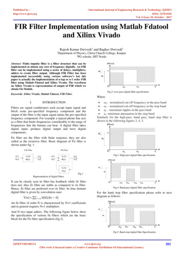
Published by :http://www.ijert.orgInternational Journal of Engineering Research & Technology (IJERT)ISSN: 2278-0181Vol. 6 Issue 10, October - 2017FIR Filter Implementation using Matlab Fdatooland Xilinx VivadoRajesh Kumar Dwivedi1 and Raghav Dwivedi21Department of Physics, Christ Church College, Kanpur2PG scholar, JIIT NoidaAbstract: Finite impulse filter is a filter structure that can beimplemented at almost any sort of frequency digitally. An FIRfilter can be implemented using a series of delays, multipliers,adders to create filter output. Although FIR Filter has beenimplemented successfully using various software’s but thispaper is actually the implementation of n-tap or n-1 order FIRfilter using Matlab Fdatool and Xilinx Vivado. The waveformon Xilinx Vivado is representation of output of FIR which weobtain On Matlab.Fig.2: Low-pass digital filter specificationKeywords: Xilinx Vivado, Matlab Fdatool, FIR Filter.WhereI.INTRODUCTIONFilters are signal conditioners each accept input signal andblock some pre-specified frequency component and theoutput of the filter is the input signal minus the pre-specifiedfrequency component. For example a typical phone line actsas a filter that limits frequencies considerably to the range offrequencies that the human can hear. A digital filter takesdigital input, produce digital output and have digitalcomponents. ωp – normalized cut-off frequency in the pass band ωs – normalized cut-off frequency in the stop band ap – maximum ripples in the pass band as- minimum attenuation in the stop bandSimilarly for the high-pass, band pass, band stop filter isshown in the following figures 3, 4, 5.Fir filter are the filter with finite response, they are alsocalled as the recursive filter. Basic diagram of Fir filter isshown under fig. 1.Fig.3: High pass digital filter specificationFig.1Representation of digital filtersIt can be clearly seen iir filter has feedback while fir filterdoes not, thus fir filter are stable as compared to iir filter.Hence, fir filter are preferred over iir filter. In time domaindigital filter is given by convolution sum:Y[n] 𝑘 ℎ[𝑘]𝑥[𝑛 𝑘]Fig.4: Band-pass digital filter specificationFor the band stop filter specification please refer to nextdiagram as followsAn fir filter of order N is characterized by N 1 coefficientsand in general requires N 1 multipliersAnd N two input adders. The following figure below showthe specification of various fir filters which are the basicblock for the Fir filter specification (fig.2).Fig.5: Band-stop digital filter SpecificationIJERTV6IS100114www.ijert.org(This work is licensed under a Creative Commons Attribution 4.0 International License.)202
Published by :http://www.ijert.orgInternational Journal of Engineering Research & Technology (IJERT)ISSN: 2278-0181Vol. 6 Issue 10, October - 2017The Z-transform is performed using with discrete-timesignals. It converts a discrete time-domain signal into afrequency-domain representation. It is very suitable foranalysing discrete time signals and systems in dsparchitectures. The z-transform is derived from the Fourierdiscrete time transformation and is considered the basicoperation in digital filter design process.The Z-transform is defined as: D. LINEAR PHASE FIR STRUCTUREThe symmetry property of a linear phase fir filter can beaccomplished to reduce the number of multipliers intoalmost half of that in the direct form implementation.Consider a length-7 type 1 fir filter; its symmetric impulseresponse is given as:𝐻(𝑧) h[0] h[1]𝑧 1 ℎ[2]𝑧 2 ℎ[3]𝑧 3 ℎ[2]𝑧 4 ℎ[1]𝑧 5 ℎ[0]𝑧 6Rewriting H (z) we get𝑋(𝑧) 𝑥(𝑛)𝑧 𝑛𝑛 Fir filter can be implemented using various structures whichare explained in the following sections.𝐻(𝑧) ℎ[0](1 𝑧 6 ) ℎ[1](𝑧 1 𝑧 5 ) ℎ[2](𝑧 2 𝑧 4 ) ℎ[3]𝑧 3We obtain the realization as shown below in fig.9A. FIR DIRECT FORMFig.6: Direct form realization of fir filterThis is called direct form because it is direct implementationof the convolution, the number of delay is the order of filter,and hence this is also called canonical form. Fig.6 shows thestructure of direct form fir, y[n] can be obtained from belowgiven equationy[n] h[0]x[n] h[1]x[n-1] h[n]x[n-N] NFig. 8 Linear Phase fir structureA similar decomposition can be applied to Type-2 Fir Filtertransfer function.II. IMPLEMENTATION OF FIR FILTERThe implementation of fir filter requires the basic threebuilding blocks viz.1) Multiplication2) Adder3) Signal delay h[k]x[k-n]k 0B. FIR CASCADED DIRECT FORMThe transpose of the direct form shown above is representedin fig.7.Building blocks of the fir filter can be shown in fig.9.Multiplier output is y[n] βx[n]Adder output is y[n] x1[n] x2[n]Fig.7: Cascade direct form realization of firFig.9: Basic building block of fir filterC. FIR CASCADE FORMA cascade realization of fir filter with N 6 is shown in fig.8Delay output is y[n] x [n-1]However DSP filter now uses MAC circuit for themultiplication followed by accumulation.Fig.8: Cascade form realization of firEach second-order section in the above structure shown infigure 8 can also be realized in the transposed direct formFig.10: MAC CircuitIJERTV6IS100114www.ijert.org(This work is licensed under a Creative Commons Attribution 4.0 International License.)203
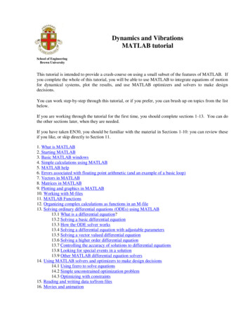
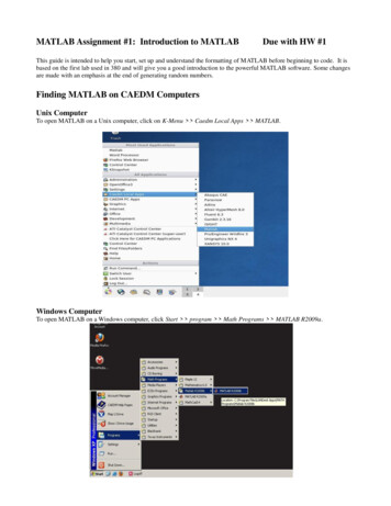
Published by :http://www.ijert.orgInternational Journal of Engineering Research & Technology (IJERT)ISSN: 2278-0181Vol. 6 Issue 10, October - 2017A typical MAC structure has been shown above in fig.10 itconsists of multiplying two values, then adding the result tothe previously accumulated value, which should be re-storedin the registers for future accumulations. Another feature ofa MAC circuit is that it must check for overflow operation inthe filter, when the number of MAC operations is large.III. MATLAB FDATOOLMATLAB FDATOOL is a filter design analysis tool usedmainly to design the filter on MATLAB platform and thentransforms it into corresponding VHDL code. In thefollowing section are the steps how to configure the FIRfilter on MATLAB.III.A GETTING STARTED WITH FDATOOLa)These settings are for the default filter design that theFilter Designer creates for you. If you do not have tochange the filter, and design filter is grayed out, you aredone and can skip to quantize the Filter.d) If you modified options listed in step c,click Design Filter. The Filter Designer creates afilter for the specified design and displays thefollowing message in the Filter Designer status barwhen the task is complete.Designing Filter. Done.Quantize filters for HDL code generation. To quantize yourfilter,e)Open the basic FIR filter design you createdin Design a FIR Filter in Filter Designer.f)Click the Set Quantization Parameters buttonin the left-side toolbar. The Filter Designer displaysa Filter arithmetic menu in the bottom half of itsdialog box.Type fdatool or filterDesigner at the MATLABcommand prompt. fdatoolFig. 11 fdatool on MATLAB command windowFig.14: Quantizing the Filter in MATLABb) Filter design and analysis toolbox appear as shownin the figure 12e) Set the quantization parameters as shown in the figurebelowFig. 15 Quantization parameters of the filterg)Fig. 12: FDATOOL box in MATLABc)After quantizing the filter we need to set the coderoption and generate VHDL code from theMATLAB. Select target generate HDL from filterdesigner dialog box.In the Filter Design & Analysis Tool dialog box,check that the following filter options are set:Fig. 13: FDATOOL options in FDATOOL boxIJERTV6IS100114Fig. 16 filter design box in MATLABwww.ijert.org(This work is licensed under a Creative Commons Attribution 4.0 International License.)204
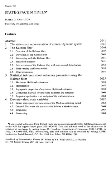
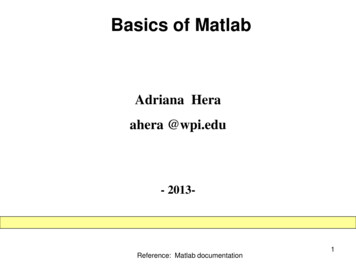
Published by :http://www.ijert.orgInternational Journal of Engineering Research & Technology (IJERT)ISSN: 2278-0181Vol. 6 Issue 10, October - 2017h) Change the default name in the target window tobasicfirFig.17 Target window in MATLABi) Open the global setting tab of the filter and writeTutorial-Basic FIR filter in the comment in headertext boxFig. 22 Testbench box in MATLABn) Click on generate button to start generate process.The coder displays the message as in the commandwindow shown in the following figure.Fig. 18 Global setting box for Filterj) Select the ports in the additional setting portion ofthe GUI.Fig. 23 Message in Command windowo) After the successful generation of VHDL codesanalyse it on XILINX VIVADO. The waveformsare shown in the next segment of this paper.Fig. 19 Ports in the additional setting at the GUIk) Replace filter in with data in and filter out withdata out in the input port text boxIV. ANALYSIS OF VHDL CODE ON XILINXVIVADOThe following VHDL code along with the testbench isgenerated using MATLAB FDATOOLS and the followingcode is analysed using Xilinx vivado the waveform obtainedis then compared with the waveform posted on MATLABtutorials. The waveform is shown below.Fig. 20 Changes in the input port text boxl)Clear the add input register option from the inputport text box then the box looks like as shown.Fig.24 (a) Waveform-I on Xilinx vivadoFig.24 (b) Waveform-II on Xilinx vivadoFig. 21 Input port text box final look after following instructionm) In the testbench tab, the file name box should havebasicfir tb as its entry onto it.IJERTV6IS100114RTL netlist of the following is generated as shown in thefigure below, since the size of the filter is 51 tap so it’simpossible to capture in the screenshot but still someglimpse of that 51 tap filter is shown here:www.ijert.org(This work is licensed under a Creative Commons Attribution 4.0 International License.)205
Published by :http://www.ijert.orgInternational Journal of Engineering Research & Technology (IJERT)ISSN: 2278-0181Vol. 6 Issue 10, October - 2017Fig. 25 RTL Netlist of the FIR Filter on Xilinx VivadoThe project summary of the following filter is shown below:Fig. 26 post-implementation of fir filterV. FUTURE SCOPE AND APPLICATION1) With the help of the MATLAB it’s almost easy todesign the FIR filter as it provide easy and suitableplatform for the implementation of the FIR filter.MATLAB along with XILINX are helpful for the fastand error-free implementation of FIR filter.2) MATLAB provide easy approach to generate VHDLcode for any configuration and any order.3) The following tutorial focuses on the practical aspectsof FIR filter design. Practically, it is possible to designany FIR filter using MATLAB.4) The coefficient in the FIR filter can be fixed-point orfloating-point or even distributed arithmetic algorithmetc. can be implemented using MATLAB.5) It’s easy to configure and generate summary for thesuccessful implementation of the FIR filter.6) Time- efficient implementation of the FIR Filter ispossible using FDATOOLS.REFERENCESFig. 27 Post-synthesis and power on-chip of FIR filterThus, the following FIR filter is successfully designed usingMATLAB FDATOOLS and the XILINX VIVADO. Theorder of the filter is 50. This type of filter can be made usingfloating point, fixed point or even the distributed arithmeticcoefficient and the MATLAB provides the platform for allthe type of algorithm. FDATOOL provide the platform forthe fixed point or the floating point coefficient, however fordistributed arithmetic we have to follow some otherprocedure to configure it successfully.However, with the help of following paper it’s easy torecognize the use of MATLAB in transforming theMATLAB code to the VHDL code significantly, this paperwill provide all the steps for designing the FIR filter. Thefilter order can vary for different design.In the recent development the Xilinx platform has provideall the significant and necessary information for thedesigning of the filter.IJERTV6IS100114[1] Practical FIR Filter Design in MATLAB, Ricardo A. Losada,The MathWorks, Inc, 3 Apple Hill Dr. Natick, MA 01760,USA January 12, 2004.[2] Introduction to Signal Processing, Prentice Hall, S. J.Orfanidis, Upper Saddle River, 1996.[3] Theory and Application of Digital Signal Processing, L. R.Rabiner and B. Gold, Prentice Hall, Englewood Cliffs, 1975.[4] Design of computationally efficient interpolated FIR filters,”T. Saramaki, Y. Neuvo, and S. K. Mitra, IEEE Trans. onCircuits and Systems, vol. 35, N0. 1,pp. 70-88, January 1988[5] Exchange algorithms that complement the Parks-McClellanalgorithm for linear-phase FIR filter design, I. W. Selesnickand C. S. Burrus, IEEE Trans. on Circuits and Systems II,44(2):137-142, February 1997.[6] Sakshat virtual labs, Digital FIR filter design and simulation,NME-ICT initiative of MHRD.[7] MATLAB FDATOOLS, MATHWORKS tutorials[8] Circuit design and simulation with VHDL, The MIT Press,Volnei A. pedroni,2010[9] XILINX VIVADO tutorial, Xilinx[10] VHDL Primer by J.Bhaskar[11] Design and verification of FIR filter based on MATLABand DSP, Chen-Long Hu, IEEE 2012 InternationalConference on Image Analysis and Signal Processing(IASP), 10.1109/IASP.2012.6425042www.ijert.org(This work is licensed under a Creative Commons Attribution 4.0 International License.)206
FIR Filter Implementation using Matlab Fdatool and Xilinx Vivado . Rajesh Kumar Dwivedi1 and Raghav Dwivedi2. 1Department of Physics, Christ Church College, Kanpur 2PG scholar, JIIT Noida . Abstract: Finite impulse filter is a filter structure that can