Transcription
802CHEMICAL ENGINEERINGEnthalpy of steam saturated at 101.3 kN/m2 2676 kJ/kg.Thus:and:at a cost of:and hence:energy from steam (2764 2676) 88 kJ/kg or 0.088 MJ/kgsteam required (0.489/0.088) 5.56 kg/kg evaporation(0.01 5.56)/10 0.0056 /kg water evaporatedthe Diesel engine would be used for driving the compressor.14.6. EVAPORATOR OPERATIONIn evaporation, solids may come out of solution and form a deposit or scale on the heattransfer surfaces. This causes a gradual increase in the resistance to heat transfer and, ifthe same temperature difference is maintained, the rate of evaporation decreases with timeand it is necessary to shut down the unit for cleaning at periodic intervals. The longerthe boiling time, the lower is the number of shutdowns which are required in a givenperiod although the rate of evaporation would fall to very low levels and the cost per unitmass of material handled would become very high. A far better approach is to make abalance which gives a minimum number of shutdowns whilst maintaining an acceptablethroughput.It has long been established(18) that, with scale formation, the overall coefficient of heattransfer may be expressed as a function of the boiling time by an equation of the form:1/U 2 atb b(14.11)where tb is the boiling time. If Qb is the total heat transferred in this time, then:dQb UA Tdtband substituting for U from equation 14.11 gives:dQbA T dtb(atb b)0.5(14.12)Integrating between 0 and Qb and 0 and tb gives:Qb (2A T /a)[(atb b)0.5 b0.5 ](14.13)There are two conditions for which an optimum value of the boiling time may besought–the time whereby the heat transferred and hence the solvent evaporated is amaximum and secondly, the time for which the cost per unit mass of solvent evaporatedis a minimum. These are now considered in turn.Maximum heat transferIf the time taken to empty, clean and refill the unit is tc , then the total time for onecycle is t (tb tc ) and the number of cycles in a period tP is tP /(tb tc ). The total
EVAPORATION803heat transferred during this period is the product of the heat transferred per cycle and thenumber of cycles in the period or:QP (2A T /a)[(atb b)0.5 b0.5 ][tP /(tb tc )](14.14)The optimum value of the boiling time which gives the maximum heat transferred percycle is obtained by differentiating equation 14.14 and equating to zero which gives:tbopt tc (2/a)(abtc )0.5(14.15)Minimum costTaking Cc as the cost of a shutdown and the variable cost during operation including alabour component as Cb , then the total cost during period tP is:CT (Cc tb Cb )tP /(tb tc )and substituting from equation 14.14:CT [aQP (Cc tb Cb )]/2A T [atb b)0.5 b0.5 ](14.16)The optimum value of the boiling time to give minimum cost is obtained by differentiatingequation 14.16 and equating to zero to give:tbopt (Cc /Cb ) 2(abCc Cb )0.5 /(aCb )(14.17)In using this equation, it must be ensured that the required evaporation is achieved. If thisis greater than that given by equation 14.17, then it is not possible to work at minimumcost conditions. The use of these equations is illustrated in the following example whichis based on the work of HARKER(19) .Example 14.7In an evaporator handling an aqueous salt solution, the overall coefficient U (kW/m2 deg K) isgiven by a form of equation 14.14 as:1/U 2 7 10 5 tb 0.2,the heat transfer area is 40 m2 , the temperature driving force is 40 deg K and the latent heat ofvaporisation of water is 2300 kJ/kg. If the down-time for cleaning is 15 ks (4.17 h), the cost of ashutdown is 600 and the operating cost during boiling is 18/ks ( 64.6/h), estimate the optimumboiling times to give a) maximum throughput and b) minimum cost.Solution(a) Maximum throughputThe boiling time to give maximum heat transfer and hence maximum throughput is given byequation 14.15:tbopt (15 103 ) (2/(7 10 5 ))(7 10 5 0.2 15 103 )0.5 2.81 104 s or 28.1 ks (7.8 h)
804CHEMICAL ENGINEERINGThe heat transferred during boiling is given by equation 14.13:Qb (2 40 40)(7 10 5 )[((7 10 5 2.81 104 ) 0.2)0.5 0.20.5 ] 4.67 107 kJand the water vaporated (4.67 107 )/2300 2.03 104 kgRate of evaporation during boiling (2.03 104 )/(2.81 104 ) 0.723 kg/sMean rate of evaporation during the cycle 2.03/[(2.8 104 ) (15 103 )] 0.471kg/s.Cost of the operation ((2.81 104 18)/1000) 600 1105.8 /cycle(1105.8/(2.03 104 ) 0.055 /kg.or:(b) Minimum costThe boiling time to give minimum cost is given by equation 14.17:tbopt (600/0.018) [2(7 10 5 0.2 600 0.018)0.5 ]/(7 10 5 0.018) 5.28 104 s or 52.8 ks(14.7 h)The heat transferred during one boiling period is given by equation 14.13:Qb [(2 40 40)/(7 10 5 )][7 10 5 5.28 104 0.2)0.5 0.20.5 ] 6.97 107 kJand the water evaporated (6.97 107 )/2300 3.03 104 kgRate of evaporation during boiling (3.03 104 )/(5.28 104 ) 0.574 kg/sMean rate of evaporation during the cycle (3.03 104 )/[(5.28 104 ) (15 103 )] 0.45 kg/sIn this case, cost of one cycle (5.28 104 0.018) 600 1550.4or:1550.4/(3.03 104 ) 0.0512 /kgThus, the maximum throughput is 0.471 kg/s and the throughput to give minimum cost, 0.0512 /kg, is 0.45 kg/s. If the desired throughput is between 0.45 and 0.471 kg/s, then this can beachieved although minimum cost operation is not possible. If a throughput of less than 0.45 kg/sis required, say 0.35 kg/s, then a total cycle time of (3.03 104 )/0.35 8.65 104 s or 86.5 ksis required. This could be achieved by boiling at 0.423 kg/s for 71.5 ks followed by a shutdownof 15 ks, which gives a cost of 0.0624 /kg. This is not the optimum boiling time for minimumcost and an alternative approach might be to boil for 52.8 ks at the optimum value, 0.45 kg/s, and,with a shutdown of 15 ks, a total cost of 0.0654 /kg is estimated which is again higher than theminimum value. It would be, in fact, more cost effective to operate with the optimum boiling timeof 52.8 ks and the down-time of 15 ks and to close the plant down for the remaining 18.7 ks ofthe 86.5 ks cycle. In this way, the minimum cost of 0.0512 /kg would be achieved. In practice,the plant would probably not be closed down each cycle but rather for the equivalent period sayonce per month or indeed once a year. In all such considerations, it should be noted that, when aplant is shut down, there is no return on the capital costs and overheads which still have to be paidand this may affect the economics.Whilst calculated optimum cycle times may not exactly correspond to convenient operatingschedules, this is not important as slight variations in the boiling times will not affect the economicsgreatly.
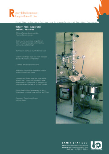
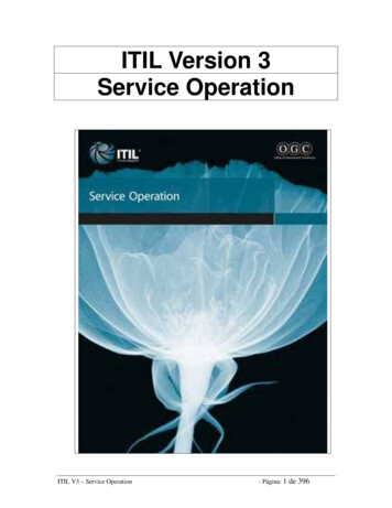
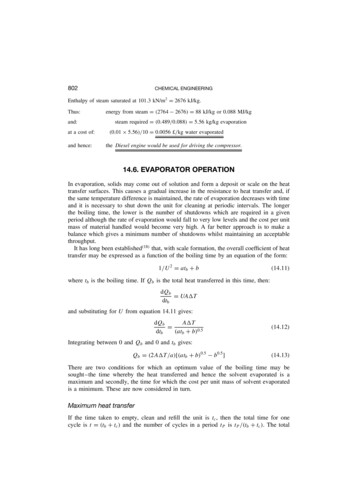
EVAPORATION80514.7. EQUIPMENT FOR EVAPORATION14.7.1. Evaporator selectionThe rapid development of the process industries and of new products has provided manyliquids with a wide range of physical and chemical properties all of which require concentration by evaporation. The type of equipment used depends largely on the method ofapplying heat to the liquor and the method of agitation. Heating may be either direct orindirect. Direct heating is represented by solar evaporation and by submerged combustionof a fuel. In indirect heating, the heat, generally provided by the condensation of steam,passes through the heating surface of the evaporator.Some of the problems arising during evaporation include:(a) High product viscosity.(b) Heat sensitivity.(c) Scale formation and deposition.Equipment has been developed in an attempt to overcome one or more of these problems.In view of the large number of types of evaporator which are available, the selectionof equipment for a particular application can only be made after a detailed analysis ofall relevant factors has been made. These will, of course, include the properties of theliquid to be evaporated, capital and running costs, capacity, holdup, and residence timecharacteristics. Evaporator selection considered in detail in Volume 6, has been discussedby MOORE and HESLER(20) and PARKER(21) . Parker has attempted to test the suitabilityof each basic design for dealing with the problems encountered in practice, and thebasic information is presented in the form shown in Figure 14.15. The factors consideredinclude the ability to handle liquids in three viscosity ranges, to deal with foaming,scaling or fouling, crystal production, solids in suspension, and heat sensitive materials.A comparison of residence time and holding volume relative to the wiped film unit isalso given. It is of interest to note that the agitated or wiped film evaporator is the onlyone which is shown to be applicable over the whole range of conditions covered.14.7.2. Evaporators with direct heatingThe use of solar heat for the production of Glauber’s salt has been described byHOLLAND(22,23) . Brine is pumped in hot weather to reservoirs of 100,000 m2 in area to adepth of 3–5 m, and salt is deposited. Later in the year, the mother liquor is drained offand the salt is stacked mechanically, and conveyed to special evaporators in which hotgases enter at 1150–1250 K through a suitable refractory duct and leave at about 330 K.The salt crystals melt in their water of crystallisation and are then dried in the stream ofhot gas. BLOCH et al.(24) , who examined the mechanism of evaporation of salt brines bydirect solar energy, found that the rate of evaporation increased with the depth of brine.The addition of dyes, such as 2-naphthol green, enables the solar energy to be absorbed ina much shallower depth of brine, and this technique has been used to obtain a significantincrease in the rate of production in the Dead Sea area.
806CHEMICAL ENGINEERINGFigure 14.15.Evaporator selection (after PARKER(21) )
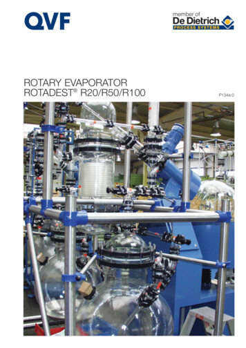
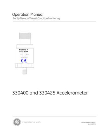
EVAPORATION807The submerged combustion of a gas, such as natural gas, has been used for theconcentration of very corrosive liquors, including spent pickle liquors, weak phosphoricand sulphuric acids. A suitable burner for direct immersion in the liquor, as developed bySWINDIN(25) , is shown in Figure 14.16. The depth of immersion of the burner is determinedby the time of heat absorption and, for example, a 50 mm burner may be immersed by250 mm and a 175 mm burner by about 450 mm. The efficiency of heat absorption ismeasured by the difference between the temperature of the liquid and that of the gasesleaving the surface, values of 2–5 deg K being obtained in practice. The great attractionof this technique, apart from the ability to handle corrosive liquors, is the very greatheat release obtained and the almost instantaneous transmission of the heat to the liquid,typically 70 MW/m3 .Figure 14.16.Burner for submerged combustion(25)14.7.3. Natural circulation evaporatorsWhilst each of the previous types of evaporator is of considerable importance in a givenindustry, it is the steam-heated evaporator that is the most widely used unit in the processindustries and this is now considered in detail. In Chapter 9 of Volume 1, it is shown thatthe movement of the liquid over the heating surface has a marked influence on the rateof heat transfer, and it is thus convenient to classify evaporators according to the methodof agitation or the nature of the circulation of the liquor over the heating surface. On thisbasis evaporators may be divided into three main types:(a) Natural circulation units.(b) Forced circulation units.(c) Film-type units.
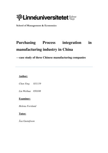
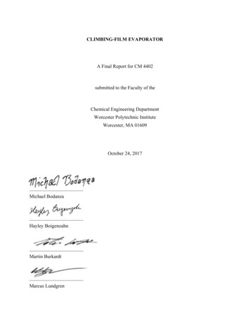
808CHEMICAL ENGINEERINGThe developments that have taken place have, in the main, originated from the sugarand salt industries where the cost of evaporation represents a major factor in the processeconomics. In recent years, particular attention has been given to obtaining the mostefficient use of the heating medium, and the main techniques that have been developedare the use of the multiple-effect unit, and of various forms of vapour compression units.With natural-circulation evaporators, circulation of the liquor is achieved by convectioncurrents arising from the heating surface. This group of evaporators may be subdividedaccording to whether the tubes are horizontal with the steam inside, or vertical with thesteam outside.Rillieux is usually credited with first using horizontal tubes, and a unit of this type isshown in Figure 14.17. The horizontal tubes extend between two tube plates to which theyare fastened either by packing plates or, more usually, by expansion. Above the heatingsection is a cylindrical portion in which separation of the vapour from the liquid takesplace. The vapour leaves through some form of de-entraining device to prevent the carryover of liquid droplets with the vapour stream. The steam enters one steam chest, passesthrough the tubes and out into the opposite chest, and the condensate leaves through asteam trap. Horizontal evaporators are relatively cheap, require low head room, are easyto install, and are suitable for handling liquors that do not crystallise. They can be usedeither as batch or as continuous units, and the shell is generally 1–3.5 m diameter and2.5–4 m high. The liquor circulation is poor, and for this reason such units are unsuitablefor viscous liquors.Figure 14.17.Natural circulation evaporator with horizontal tubesThe use of vertical tubes is associated with Robert, and this type is sometimes knownas the Robert or Standard Evaporator. A typical form of vertical evaporator is illustratedin Figure 14.18, in which a vertical cylindrical body is used, with the tubes held betweentwo horizontal tube plates which extend right across the body. The lower portion of theevaporator is frequently spoken of as the calandria section shown in Figure 14.19. Tubes
EVAPORATIONFigure 14.18.Evaporator with vertical tubes and a large central downcomerFigure 14.19.Calandria for an evaporator809
810CHEMICAL ENGINEERINGare 1–2 m in length and 37–75 mm diameter, giving ratio of length to inside diameterof the tubes of 20–40. In th
In an evaporator handling an aqueous salt solution, the overall coefficient U(kW/m2 deg K) is given by a form of equation 14.14 as: 1/U2 7 10 5t b 0.2, the heat transfer area is 40 m2, the temperature driving force is 40 deg K and the latent heat of vaporisation of water is 2300 kJ/kg. If the down-time for cleaning is 15 ks (4.17 h), the cost of aFile Size: 406KBPage Count: 25People also search forevaporator operationrotary evaporator pdffalling film evaporator pdfmultiple effect evaporator pdfevaporator designgeneral principles of evaporation