Transcription
Autodesk Robot Structural Analysis:Steel and RC DesignArtur Kosakowski – AutodeskSE54225In this class we will cover the workflow for design of steel and RC structures starting with building the bestpossible model for a task followed by assigning correct design parameters and finding the optimal steelsection sizes or reinforcement arrangement.Learning ObjectivesAt the end of this class, you will be able to: Create a model of a structure that matches needs of the Steel and RC design modules of AutodeskRobot Structural Analysis Professional Define loads and load combinations to be correctly recognized in the design modules Apply principles of steel and concrete design modules and understand the influence of definedparameters on the design process Run concrete design of elements of a modelAbout the SpeakerArtur is a Structural Engineer. He graduated from Cracow's University of Technology. He has beenworking as a Support Specialist since 1996 at Robobat and since 2008 at Autodesk supporting Robot’susers worldwide.
Autodesk Robot Structural Analysis: Steel and RC DesignIntroductionRegardless of what kind of a structure you are about to design it is extremely important that youcreate its model in the manner that allows you to assign the correct design parameters to each of itselements. This document will not be a step by step guideline to follow but it will show you the waysfor having models which are coherent with the design modules of RSA as well as indicate the rulesthat govern both steel and RC design in the program.The topics discussed in this presentation are based both on my own experience as well as threadsfrom Robot forum which I would like to encourage you to use as a platform to discuss them furtheror the place where you can both find help for your challenging issues and help others solve theirs.2
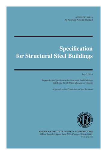
Autodesk Robot Structural Analysis: Steel and RC Design1. Building a modela) For Steel design Define bar elements in such a way it is easy to assign design parameters. Consider their role in astructure and design criteria Create multi span beams as single elements among supports (columns) rather than singleelements and cantilevers as separate bars so that it is easy to define SLS (deflection) limits Enter columns as single elements instead of being defined through the entire height of astructure which allows for both defining their displacement limits as well assigning them to thestories (seismic analysis)3
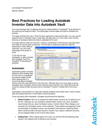
Autodesk Robot Structural Analysis: Steel and RC Design Use ‘’superbars” in case there is a need to split columns and beams between supports e.g. todefine a connection or to change its section size (e.g. increase thickness of flanges of I section)on a part of its length4
Autodesk Robot Structural Analysis: Steel and RC DesignMind that the local X axes of components of a “superbar” should point in the same direction.Mind that the orientation of a “superbar” doesn’t follow the direction of the local coordinatesystems of its components. It is governed by the number of its origin and end node instead (lowernode number is assumed as the start whereas the higher one as the end). To replace the origin withthe end it is necessary to renumber the nodes which can be done using the numbering option. Use offsets (bar shortening) to generate additional bending moments on columns whichoriginate from pinned connections of beams to their flangesThe relative definition of the offset for a member length automatically adjusts its value to a changein the size of a column.5
Autodesk Robot Structural Analysis: Steel and RC Design Trusses from library structures – to avoid instabilities it is recommended to create continuouschords and use releases or truss bar definitions on posts and diagonals only. It should beremembered to delete side posts which for typical situations overlap with already definedcolumns To define partial releases which represent real stiffness of connections you can use elasticrelease definition6
Autodesk Robot Structural Analysis: Steel and RC DesignA similar approach (partial releases) may be used to obtain additional bending in pinnedconnections among elements of a model for having safety margin.Additional references to the discussions on these topics on the Robot 407
Autodesk Robot Structural Analysis: Steel and RC Designb) For RC design Define bar elements with section types supported in design modules (neither use an RC Beamsection for or an RC Column definition and vice versa nor use steel ones for either of them) Define bar elements and surfaces in such a way it is easy to assign design parameters. Considertheir role in a structure and design criteria.-You can create multi span beams as single elements among supports (columns) or as a singlebar between the outside ones when you want to design them in the RC Beam Design module asit automatically detects spans but define spans of beams as separate bars if you intend tocalculate required area of reinforcement inside the RC Member Required reinforcement moduleto be able to correctly define deflection limits8
Autodesk Robot Structural Analysis: Steel and RC Design Enter columns as single elements instead of being defined through the entire height of astructure which allows for both defining their buckling parameters as well assigning them tothe stories (seismic analysis). In addition you may find the access to their results easierespecially in the Forces table. Do not divide columns and beams between supports or stories (levels of beams) into smallerparts as such chains of elements are not supported correctly in the RC design module (with theexception of RC Beam Design one) To define RC Columns of different sizes at top of each other you can use offsets or(recommended) rigid links. If there is a slab “between” them you can define them in their realpositions as they (top node of a bottom one and bottom node of a top one) will be connected bymesh elements of the slab.9
Autodesk Robot Structural Analysis: Steel and RC Design I shape RC Beams can only be designed in the RC Member Required reinforcement module. It is not recommended to use vertical offsets for RC Beams you want to design reinforcementfor as they influence values of internal forces causing large increase of the axial force (tension)and significant reduction of the bending moment10
Autodesk Robot Structural Analysis: Steel and RC Design --To design a T shape beam under a slab (panel) without using the offsets (for the reasonsexplained above) you may follow these steps:define a beam with a rectangular cross section that represents T shape “web” with no offsetincrease its IY moment of inertia so that it is the same as the T shape it “replaces”replace the rectangular section with the “original’ T one after exporting a beam from a model tothe RC Beam Design module11
Autodesk Robot Structural Analysis: Steel and RC Design In order to model curved RC beams you need to approximate them with number of smallerstraight elements.Then you can calculate required area of reinforcement in the RC Member Requiredreinforcement module. In order to correctly export a bar element from a model that represent a strap footing to the RCContinuous Footing (rather than to RC Beam) design module you should:- Define elastic soil as its attribute- Set it Structure object as Bar- In case of a T shape cross section assign it 180 (Gamma) rotation angle12
Autodesk Robot Structural Analysis: Steel and RC Design To obtain correct values of “cracked” deflection of a multi span slab with use of the equivalentstiffness method you should create number of smaller panel among the support lines ratherthan a single one “covering” the entire shape of the floor.There are two main reasons for such way of creating a model:-Equivalent stiffness of RC plate (see: Help) is calculated for each of the “spans” (panels)separately which is important for different geometries and loads on each of panelsScaling of elastic displacements is done for load which causes maximal deformation for givenpanel rather than for the load which causes maximal displacements from the point found in theentire floor.13
Autodesk Robot Structural Analysis: Steel and RC DesignOtherwise the stiffness update method should be used instead. To obtain unidirectional behavior of a slab in a model you may use the orthotropic thicknessdefinition instead of the homogenous one and reduce value of Young modulus in the directionthe slab is not supposed to “work”14
Autodesk Robot Structural Analysis: Steel and RC Design -To define raft foundation you should you should define elastic soil as either:parameter of its thickness (recommended for it allows for display of stress in soil as a map)-or elastic planar (surface) elastic support. Mind not to mark the Constant coefficient check boxto allow the stiffness of each support generated in panel’s node to be automatically calculatedbased on tributary area of elements of a mesh.Do not use both of them at the same time as the defined soil stiffness will add up.15
Autodesk Robot Structural Analysis: Steel and RC DesignAdditional references to the discussions on these topics on the Robot 93516
Autodesk Robot Structural Analysis: Steel and RC Design2. Defining loads Live load applied on a multi span beam or slab defined in the model of a structure acts asapplied (there is no automatic pattern load distribution). In case this is needed it should bereplace with number of live loads defined on each of spans separately. It is suggested to do soonly for currently designed level (story) or do so for a substructure saved based on theselection of a part (e.g. floor plus walls and column above and below it) of the entire model In case of multi-story building limit number of combinations to a reasonable value. The limit ofautomatically generated combinations can be entered in Job Preferences In order to avoid the effect of unrealistic shortenings of RC Columns under self-weight of higherstories you can apply load in stages (phases)Additional references to the discussions on these topics on the Robot p/456868917
Autodesk Robot Structural Analysis: Steel and RC Design3. Working with the Steel Design modulea) Setting design parameters (Member type definition) Beams - the proposed setting for typical situations is to use automatic detection of bracings asshown below:18
Autodesk Robot Structural Analysis: Steel and RC DesignIn addition for beams with large negative bending over supports you may decide to limitunrestrained lateral buckling length for the bottom flange to the parts where it is undercompression19
Autodesk Robot Structural Analysis: Steel and RC Design Columns – the use of automatic buckling length should be limited to ‘box’ shaped structureswith perpendicular beams defined among rows of columns at levels of horizontal floorsIt is strongly recommended not to alter settings for member length and keep the default 1.00coefficients in these fields.20
Autodesk Robot Structural Analysis: Steel and RC Design A beam vs. a cantilever (use of Cantilever check box) for SLS verificationIf the check box is not marked then the deflection is checked as the distance between the line thatconnects the beam ends in the positions they are after applying the load and the point along thebeam that 'moves' the most whereas for the cantilever check box marked what is checked is thedifference in displacement of the end nodes.21
Autodesk Robot Structural Analysis: Steel and RC Designb) Setting Calculations parameters (Configuration dialog) Deciding on number of calculation pointsIn general it is recommended to set relatively large number of verification points along a bar(usually the default 3 is good enough only for simply supported beams with uniform or pointload in its middle)You may reduce their number when there are additional nodes along a bar as the points are set forcalculation elements rather than the bar itself. This functionality is used to prevent “skipping” thepoint where a concentrated force is applied but in order to have it applied you need to define apoint force with a calculation node:22
Autodesk Robot Structural Analysis: Steel and RC DesignIt is recommended to have the Simultaneous calculations check box marked as max/min forcesare assumed as the ones with largest absolute values (sign is ignored) and such points may notbe the governing ones (this depends e.g. on locations of bracings as well)23
Autodesk Robot Structural Analysis: Steel and RC DesignThe results are displayed from the point where calculated ratio is the highest however you mayrun the check in an arbitrary selected location along a bar using the following settings: Excluding some internal forces from calculationsIn some situation you may want to exclude small axial forces or bending moments to run designagainst simple bending or unidirectional bending with axial force instead of biaxial bending (withaxial force)This can be done by setting the limits below which the effect they cause are considered to be smallenough to be neglected. It is recommended to use the relative stress limit as such definition is more“general” and can be applied to sections of different sizes. Mind to set both negative and positivevalues.24
Autodesk Robot Structural Analysis: Steel and RC Design Finding best matching section (Code group design)In most situations you want to find a best (the same) section for selected group of elements of amodel (e.g. internal columns on the 2nd floor or main girders of a roof) and the design criteria isweight (cost) rather than ratio closest to 1. In such case you need to create design groups based onlist of elements from such group25
Autodesk Robot Structural Analysis: Steel and RC Designand select the optimization parametersMind that the code group design (contrary to the member verification) is based on the materialassigned to the group rather than to elements that this group includes26
Autodesk Robot Structural Analysis: Steel and RC Design Finding best matching section for each beam or column of a model separatelyAs such operation can only be performed on groups it is necessary to create them for each ofelement of a model separately (one element one group). This can be done automatically by typingall/-1 in the list of bars and pressing the ENTER key Limiting search to only these profiles which are available (on stock)Marking the check box moves all profiles from the marked database or family to the selected(available for design) section list.Selecting a database allows for picking up families or single profilesIf no selection is done the design assumes that all profiles from the family of a section assignedto a beam can be used.27
Autodesk Robot Structural Analysis: Steel and RC Design Design of user created section is based on selected section type (verification path and formulasto be used) as well as entered section geometrical properties (section class determination)e.g. for I section with additional welded plates as discusses at the beginning of the presentationWhen section type is left as “?” the verification is done as for a solid rectangular profile28
Autodesk Robot Structural Analysis: Steel and RC Design Managing the results of code checkingTo check which elements failed and to what degree you can follow the steps illustrated on thepictures below:29
Autodesk Robot Structural Analysis: Steel and RC DesignAdditional references to the discussions on these topics on the Robot /td-p/496294430
Autodesk Robot Structural Analysis: Steel and RC Design4. Working with the RC Design modules To add new reinforcement bar grade or diameter you select and edit reinforcement bardatabaseIn the same way it is possible to add or edit the list of wire fabrics (meshes)The description tabs provide information about each of the columns.31
Autodesk Robot Structural Analysis: Steel and RC Designa) RC Beam Design module Import form a modelTo import a beam from a model you need to select bars which define it and press the indicatedbuttonIn addition to decision about loads you want to import mind to check the supports tab to see if theautomatic selection (based on supporting element type and its size) has been done correctly32
Autodesk Robot Structural Analysis: Steel and RC Design Calculation optionsBy default a beam is designed against the simple bending with values checked in 11 points.These settings can be changed in the Advanced (calculation) options dialogIn addition it is possible to decide if you want to calculate reinforcement for bending moment andshear force from support’s face or its middle by selecting a support type type33
Autodesk Robot Structural Analysis: Steel and RC Design Reinforcement pattern (distribution)The decision of support type influences the range of generation of stirrups. In case you want todesign a beam with concrete supports for bending moments from its middle but you don’t want tohave any stirrups generated over supports you may need to change the default settings34
Autodesk Robot Structural Analysis: Steel and RC DesignTo include constructional reinforcement in beam’s capacity you need to set its steel grade as beingthe same as the one selected for the longitudinal (main) one.b) RC Column Design moduleRC Columns in a model should be defined as a single bar elements (between levels of beams orfloors) rather than a chain of smaller ones or a single element running through all the stories. Incase of a column defined “inside” a “meshed” wall you should ignore the warning about nodesdefined along its length.35
Autodesk Robot Structural Analysis: Steel and RC Design Import form a model (grouping)RC columns are exported from a model in the same way as beams but it is possible (similarly to thegroup design in the Steel Design module) calculate identical reinforcement for group of RC columnsof the same geometry Calculation optionsBy default columns are calculated for axial force and bi-directional bending but it is possible toinclude shear and SLS design or limit bending to one direction only (when the other directionbending moment is small enough to be neglected or a column is a ’part’ of a wall)36
Autodesk Robot Structural Analysis: Steel and RC DesignMind that buckling parameters are taken from the Member type label assigned to a column in amodel.c) RC Spread Footing Design module Import form a model (grouping)Design of a spread footing is based on reactions imported from selected support nodes. It isimportant to match the directions of support with the direction of the local coordinate system of acolumn as the design of the spread footing is based on obtained values of reactions.37
Autodesk Robot Structural Analysis: Steel and RC DesignIt is possible to group nodes in order to have identical foundations in these locations.When two supported nodes are selected it is possible to design a common foundation for bothcolumns located in these nodesIt is important to match the directions of local coordinate systems of the columns38
Autodesk Robot Structural Analysis: Steel and RC Designd) Design of RC Continuous Footing For a strap foundation under isolated columns use the RC Continuous Footing moduleMind to set the Structure object type as a Bar rather than a Beam For a strap foundation under a wall with defined linear support at the bottom edge use the RCSpread footing module in the continuous footing mode39
Autodesk Robot Structural Analysis: Steel and RC Designe) RC Slab Required Reinforcement module Global averaging of forcesThe option should only be used for a situation when a slab is modeled as number of smaller panelsand there are no other panels defined in another planes. Otherwise it should be switched off.40
Autodesk Robot Structural Analysis: Steel and RC Design Reduction of peek of bending moments over point supportsAs the values of bending moments in these locations are larger than existing in reality you canreduce them based on the actual size of a support (column). The range of the reduction depends onthe mesh size therefore you need to match the dimensions of elements of the mesh and panel’ssupports e.g. size of elements being approximately from a half to the size of a real support.41
Autodesk Robot Structural Analysis: Steel and RC Design42
Autodesk Robot Structural Analysis: Steel and RC Design Selection of forces included in the reinforcement designYou can exclude small axial forces from reinforcement calculations selecting the simple bendingmode as well as exclude bending moments using the compression/tension one.Mind that for some codes there is large difference between minimal area of reinforcement forelements under pure tension (such situation may happen for the bending compression/tension)and under bending. Influence of maximal allowed bar spacing on calculated required area of reinforcementAt the stage of calculations of required area of reinforcement you may not know what bar diameterwill be finally used therefore you may assume it as larger one for safety reasons (arm of internalforces; cracks). In such case for lightly loaded slabs you may get large values due to maximalallowed bar spacing. This effect can be disabled by checking the check box marked below:43
Autodesk Robot Structural Analysis: Steel and RC Design Calculations of “cracked” slab deflectionThe equivalent stiffness method is the approximated approach based on scaling the deflectionobtained from the static analysis of a model by elastic stiffness of a panel to its “averaged” crackedstiffness factor. Due to assumption of this method it should not be used to raft foundation on elasticsoil and you should check the values of displacements obtained from static analysis instead.The stiffness update method is based on calculations of entire model with each element of a panelhaving its stiffness updated (reduced) according to calculated area of reinforcement and crackwidth. This verification can only be done for a single load case or combination at a time.44
Autodesk Robot Structural Analysis: Steel and RC Design Correction of an excessive deflection by additional reinforcementIf you mark Reinforcement adjust for deflection then the additional reinforcement is added in thelocations where the calculated cracked stiffness of a slab is much smaller than in other locations. Insome situations this may result in having very large area of reinforcement in isolated places acrossthe slab.Alternative approach is to reduce the allowable crack width which will result in having much moreuniform distribution of “additional” reinforcement needed to keep cracks below the new limitswhich will also reduce the deflection of a slab.45
Autodesk Robot Structural Analysis: Steel and RC Designf) RC Slab Provided Reinforcement module Orientation of a slab imported from a modelThe direction is governed by the local X axis of a panel (as defined in a model)46
Autodesk Robot Structural Analysis: Steel and RC Design Punching verificationThe check is based on real support (column) size therefore it is required to provide this informationwhen nodal supports are defined. This can be done in their advanced parameters. Manual definition of reinforcement zonesAs program deletes reinforcement bars which are generated in the same place it is recommended toindicate a basic panel while creating overlapping zones.47
Autodesk Robot Structural Analysis: Steel and RC Designg) Design of RC WallsThe design of provided reinforcement in a vertical panel (wall) can be done either in the same wayas for slab (RC Slab Required Reinforcement calculations in either compression/tension or bending compression tension mode followed by the RC Slab Provided Reinforcement) when its StructureObject Type is set as Panel or Flooror (for selected design codes) in the RC Wall Design module when a panel Structure Object type isset as Wall. In this case out of the plane bending is neglected.48
Autodesk Robot Structural Analysis: Steel and RC DesignAdditional references to the discussions on these topics on the Robot ns/td-p/326943549
Autodesk Robot Structural Analysis: Steel and RC ng-r
Autodesk Robot Structural Analysis: Steel and RC Design 3 1. Building a model a) For Steel design Define bar elements in such a way it is easy to assign design parameters. Consider their role in a structure and design criteria Create multi span beams as si