Transcription
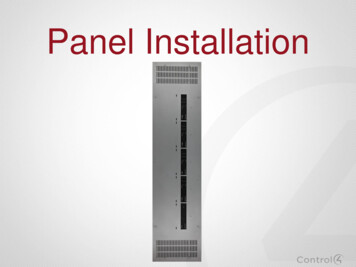
Panel Installation
Recommended Courses To better understand this training, it isrecommended that you watch thesemodules before watching this course.– Control4 Lighting Fundamentals Electricity Basics and Dimming Technologies Load Types– Control4 Panelized Lighting Introduction– Control4 Panelized Lighting System DesignUsing Composer You will be tested on some of theseconcepts in a Panelized Lighting examafter all modules are completedIf you are an Electrician, this course willhelp you with wiring of the devices. Workwith the Control4 dealer on details of whatyou are connecting so to help them withSystem Design.1/27/2015 2013 Control4 Corporation
For the Electrician These slides are more for the electrician,but you as a dealer should be aware ofsome of the basics.1/27/2015 2013 Control4 Corporation
Panel Installation - Warnings1/27/2015
Standard DIN Rails Although we are coveringthe NEW Control4 PanelInstallation, Standard DINRails can be used. Check ratings based onusing Standard DIN Railsas they will be rated lowerthan Control4 Panels.1/27/2015 2013 Control4 Corporation
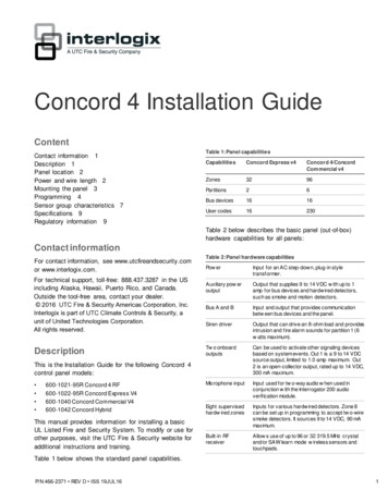
Panel Installation1551. Backbox2. Rail on right side formodule installation3. Class 1/2 divider plates4. Terminal Block mountingstandoffs5. Surface mount screwkeyholes6. Ground bar7. “Top” indicator1/27/2015 2013 Control4 Corporation372663554
Two Panel Installation OptionsSurface mountscrew keyholesSurface Mount1/27/2015Flush Mount 2013 Control4 Corporation
Panels Installation – Slot PositionsSmall – 2 slots(35” high)1/27/2015Large – 5 slots(65” high) 2013 Control4 CorporationTo fill an empty slot,use two (2) of theincluded plastic insertsin the Panel Cover.Also sold separately.
Refer to Composer Reports Before installationbegins, refer to thereports from Composer Reports will consist of– Location of Panel– Which terminal blocks andmodules go in each panel– Where the loads will beconnected Refer to reports during theentire installation1/27/2015 2013 Control4 Corporation
Panels Install – Wire Divider Divider plates arelocated at the top andbottom right side of thebackbox They can be used toseparate high and lowvoltage wires Plates swivel to adjustfor proper space1/27/2015 2013 Control4 Corporation
Terminal Blocks Used for terminating wiring in the panelDifferent terminal block for each module type– Each module type requires different wiringconfigurations.– Comes as a complete assembly alreadymounted on the rail.Sold separately– Purchased at rough-inSimilar blocks used in Crestron & Lutronpanels so electricians are familiar with them.Built-in jumpers between line-ins and loadsallow loads to be turned on/off using thebreaker prior to installing modules.– Remove once module is installed –unscrew all screws and jumper can beremoved.– Relay terminal only has 3 screws– Do NOT remove jumpers acrosswhite terminals1/27/2015 2013 Control4 Corporationjumpers
Add Terminal BlocksGood Practice isto add terminalblocks while thepanel is empty1/27/2015 2013 Control4 Corporation
Panel Installation - Label & Pull Wires in PanelPull wires toappropriate panels aslisted in reportsPull wiresthrough top orbottom of panelMake sure allwires are labeledfrom Breakerand Light Loads1/27/2015 2013 Control4 Corporation
Panel Installation – Use Wire ClampsRun the wiring through theknockouts at the top andbottom of the panelNote: If panel is flush mounted, it is abest practice not to use the front rowof knockouts because they willinterfere with drywall.1/27/2015 2013 Control4 Corporation
Panel Installation – Strip WiresStrip the jacket forthe wires at the top ofthe panelImportant: Each hot and neutral pair should be kept together asthey will need to be wired to the same terminal block. Veryimportant when using arc-fault breakers.1/27/2015 2013 Control4 Corporation
Terminal Wiringfrom Breaker andLight Loads
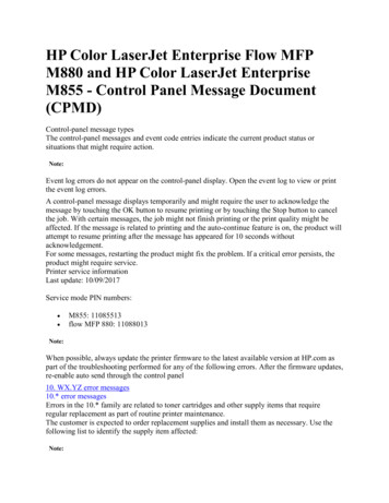
Terminal Blocks - WiringNorth America(C4-DIN-TB-8DIM)Used with Control4 8-Channel DimmerInternational countries correspond yourcolors with live, load, neutral and ground(C4-DIN-TB-8REL)Used with Control4 8-Channel Relay(C4-DIN-TB-PO)Used with 0-10V Dimmer,Ethernet Switch and Bus Power Supply1/27/2015 2013 Control4 Corporation
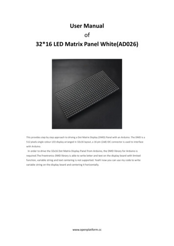
Dimmer Wiring Example8 Channel Dimmer1/27/2015 2013 Control4 Corporation
Terminal Blocks – Dimmer (From Circuit Breaker Box)1/27/2015 2013 Control4 Corporation
Terminal Blocks – Dimmer (To Light Loads)1/27/2015 2013 Control4 Corporation
Terminal Blocks – Dimmer (To Auxiliary Switch)1/27/2015 2013 Control4 Corporation
Best Practice – Ethernet Switch & Bus Power Supply Make sure the Ethernet Switchand Bus Power Supply are ontheir own circuit. If they were on same circuit asDimmer or Relay Module, theywould lose power if thesemodules tripped the breaker. Best to have thesecommunication devices share thesame circuit as other networkdevices.1/27/2015 2013 Control4 Corporation
Panel Installation – Wire Terminal BlocksRefer to the Composer reports toensure correct connectionsWire Line In Circuits,Neutrals and LoadWires from Lights toTerminal Block1/27/2015Note: Keep neutrals from the same circuit in a commonterminal block section to avoid tripping breakers 2013 Control4 Corporation
Panel Installation – Wire Terminal BlocksInstall the ground wires to theground wire bar in the panel andattach Terminal BlocksNote: Each ground terminal can accept up to two wires1/27/2015 2013 Control4 Corporation
Panel Installation – Test LightsJumperWith Jumpers inplace, test lights withCircuit Breaker1/27/2015 2013 Control4 Corporation
If Breakers Trip During TestIf breaker breaks, you must resolve theproblem before proceeding.Note: Damage due to faulty wiring is not covered under warranty1/27/2015 2013 Control4 Corporation
Wiring from Terminalsto Control4 Modules(Trimout Phase)
Modules Snap into Place1/27/2015 2013 Control4 Corporation
Panel Installation – Wire Modules Wire from Terminal Block toControl4 Modules Hint: Easier if you usestranded wire Be sure to use the samegauge as field wiring1/27/2015 2013 Control4 Corporation
8-Channel Dimmer Wiring (Circuit Breaker to Module)1/27/2015 2013 Control4 Corporation
8-Channel Dimmer Wiring (Loads to Module)1/27/2015 2013 Control4 Corporation
8-Channel Dimmer Wiring (To Ethernet Switch)1/27/2015 2013 Control4 Corporation
Panel Installation – Take Out JumpersJumperTake out Jumpers toactivate modulesNote: Be sure to remove only jumpers connecting black to red. Do NOTremove jumpers connecting white to white or black to black.1/27/2015 2013 Control4 Corporation
Panel Installation – TestTest Lights andDevices fromButtons on ModulesNote: In the factory setting, all channels are set to Switch Mode in casethe channel is connected to a non-dimmable load – dimming propertiesare set by using module setup or Composer1/27/2015 2013 Control4 Corporation
Operation of Modules
Button Presses Identify– 4 presses on Channel 1 Reboot Device– 15 presses on Channel 1 Factory Reset– 9 presses on Channel 1– 4 presses on Channel 8– 9 presses on channel 11/27/2015 2013 Control4 Corporation
Troubleshooting
Control4 Module - Troubleshooting1/27/2015 2013 Control4 Corporation
Module Fault Detection The Modules are designed toprotect themselves– Overtemp Faults Either the module is not gettingenough airflow or it is being over it’sload rating Module Override LED will turn RED When temperature is lower, fault willclear1/27/2015 2013 Control4 Corporation
Module Fault Detection The Modules are designed toprotect themselves– Short Circuit Fault Nail hits wire High in-rush current Large current spike from burn out ofincandescent bulb Dimming a non-dimmable load– Load will turn off and LEDwill turn to RED– Turn load back on to clearthe fault or address theunderlying problem1/27/2015 2013 Control4 Corporation
Clearing a Fault If fault happens within 10seconds of turning loadon again– Correct the underlyingproblem– Press and hold channelbutton for 5 seconds toclear the fault– Composer can be used toclear a fault as well1/27/2015 2013 Control4 Corporation
Module Setup Procedure Press the CH1 and CH8 buttons simultaneously. All channel LEDs will change color indicating the current dimming mode:––––Solid Yellow – Switch ModeSolid Red – Autodetect ModeSolid Green – Forward Phase ModeSolid Blue – Reverse Phase Mode Click each channel button to cycle through the four (4) dimming mode types. Once each channels is set as desired, click the Module Override button toinitiate the autodetect sequence on any channels set to ‘Autodetect Mode.’ Thechannel being autodetected will blink Red. When the autodetect test isfinished, the channel LED will go to one of the following states:–––1/27/2015Blinking Green – Autodetected forward phaseBlinking Blue – Autodetected reverse phaseSolid Red – Autodetect failed. Test should be run again or an alternate mode should be set
Module Setup Procedure Exit the configuration mode by pressing and holding the Module Overridebutton briefly. If any channels are still set to Autodetect (solid red), theautodetect sequence will run for those channels. The above procedure should be repeated anytime that a module is rewired ora load type changes. NOTE: Once the module has been identified into a project, it is no longerpossible to configure the dimming mode from the module. The dimmable/non-dimmable load type and dimming mode settings in Composer must beused to configure the dimming mode. NOTE: When first identifying a module into a project, if the dimming mode ofthe light in Composer conflicts with the dimming mode of the correspondingchannel on the module, a warning will be presented forcing the user tochoose the appropriate dimming mode.1/27/2015
Tools for urces#documents1/27/2015 2013 Control4 Corporation
Frequently Asked Questions1/27/2015 2013 Control4 Corporation
FAQs Does Control4 offer different colorterminal blocks for other countries?– No, we only have the three terminalblocks. Refer to the wiring diagram toproperly connect your local colors to theappropriate terminal block section.1/27/2015 2013 Control4 Corporation
FAQs Is it ok to use solid wire from the terminalblock to modules?– You can use solid wire, but stranded isrecommended if code permits, only because it ismore flexible and easier to make theconnections. Just be sure to use thesame gauge as the wire from the circuit panel.VS.1/27/2015 2013 Control4 Corporation
FAQs Can I use other manufacturers terminalblocks with the Control4 modules andPanels?– You could use another manufacturers Terminal Blocks as longas they install using standard 35mm Din rail mounts. With thissaid, it is highly recommended that you use the Control4Terminal Blocks since they are configured forthe correct devices, making it easier to wire.1/27/2015 2013 Control4 Corporation
Review – Installation Steps1.Install Panels according to reports – Flush or surface mount.2.Good practice to install Terminal Blocks while panel is empty. Make sure wire dividers are in place.3.Pull wires into panel from breaker and loads. Use wire clamps at the entry into panel. Make sure wiresare labeled according to Composer report.4.Strip jacket from wire keeping each hot and neutral together. Connect ground wires to ground bus bar(s). Connect wires from ground bus to each terminal block. Connect line, neutral & load wires to terminal block according to module report5.With Terminal Block jumpers in place, test the loads with breaker to confirm wiring is correct.6.Trim out Phase: Install Modules in panel. Wire from Terminal Block according to Composer report.7.Take Terminal Block Jumpers out and now test the loads with Module buttons.8.Confirm LEDs correspond with state of load.9.Add Modules to Network.10. Confirm Keypads will operate the loads.11. Replace cover to panel and install inserts where needed.1/27/2015
Thank You
– Control4 Panelized Lighting Introduction – Control4 Panelized Lighting System Design Using Composer You will be tested on some of these concepts in a Panelized Lighting exam after all modules are completed If you are an Electrician, this course will help you with wiring of the devices. Work wit