Transcription
Service ManualCubelet Icemaker/DispenserModelsDCM-270BAH(-OS)F-A & F-C Control Boardshoshizakiamerica.comNumber: 73202Issued: 5-6-2014Revised: 5-10-2016
WARNINGOnly qualified service technicians should install and service the icemaker. Toobtain the name and phone number of your local Hoshizaki Certified ServiceRepresentative, visit www.hoshizaki.com. No service should be undertaken untilthe technician has thoroughly read this Service Manual. Failure to service andmaintain the appliance in accordance with this manual will adversely affect safety,performance, component life, and warranty coverage and may result in costly waterdamage. Proper installation is the responsibility of the installer. Product failure orproperty damage due to improper installation is not covered under warranty.Hoshizaki provides this manual primarily to assist qualified service technicians in theservice and maintenance of the appliance.Should the reader have any questions or concerns which have not been satisfactorilyaddressed, please call, send an e-mail message, or write to the Hoshizaki TechnicalSupport Department for assistance.Phone: 1-800-233-1940; (770) 487-2331Fax: 1-800-843-1056; (770) 487-3360E-mail: techsupport@hoshizaki.comHOSHIZAKI AMERICA, INC.618 Highway 74 SouthPeachtree City, GA 30269Attn: Hoshizaki Technical Support DepartmentWeb Site: www.hoshizaki.comNOTE: To expedite assistance, all correspondence/communication MUST include thefollowing information: Model Number Serial Number Complete and detailed explanation of the problem.2
IMPORTANTThis manual should be read carefully before the appliance is serviced. Readthe warnings and guidelines contained in this booklet carefully as they provideessential information for the continued safe use, service, and maintenance of theappliance. Retain this booklet for any further reference that may be necessary.CONTENTSImportant Safety Information. 4I. Construction and Water Refrigeration Circuit Diagrams. 6A. Construction. 6B. Water/Refrigeration Circuit Diagrams. 7II. Sequence of Operation and Service Diagnosis. 8A. Sequence of Operation Flow Chart. 8B. Service Diagnosis. 9C. Control Board Check. 14D. Bin Control Check. 23E. Float Switch Check and Cleaning. 25F. Diagnostic Tables. 27III. Controls and Adjustments. 31A. Control Board Layout. 32B. LED Lights and Audible Alarm Safeties. 34C. Settings and Adjustments. 351. Default Dip Switch Settings. 352. Bin Control Shutdown Delay (Infrared Sensor) (S1 dip switch 1, 2, 3). 353. Drain Frequency Control (S1 dip switch 4). 354. Continuous Dispensing Timer (S1 dip switch 5 & 6). 365. Bin Control Selector (S1 dip switch 7). 366. Bin Control Shutdown Delay, Agitation, and Ice Purge Timer (S1 dip switch 8). 367. Bin Control Shutdown Delay (S1 dip switch 9) (F-C CB Only). 378. Factory Use (S1 Dip Switch 10). 37D. Switches. 37IV. Refrigeration Circuit and Component Service Information. 38A. Refrigeration Circuit Service Information. 38B. Component Service Information. 41C. Icemaking Unit. 43V. Maintenance. 49VI. Preparing the Appliance for Periods of Non-Use. 50VII. Disposal. 51VIII. Technical Information. 52A. Specification and Performance Data Sheets. 521. DCM-270BAH. 522. DCM-270BAH-OS. 53B. Wiring Diagrams. 541. DCM-270BAH(-OS): . 54Serial Number: C10508L to D00829A (except C17634M and C17641M). 542. DCM-270BAH(-OS): . 55Serial Number: C17634M, C17641M, and D-00998A and Later. 553
Important Safety InformationThroughout this manual, notices appear to bring your attention to situations which couldresult in death, serious injury, damage to the appliance, or damage to property.WARNINGIndicates a hazardous situation which could result in death orserious injury.NOTICEIndicates a situation which could result in damage to theappliance or property.IMPORTANTIndicates important information about the use and care of theappliance.WARNINGThe appliance should be destined only to the use for which it has been expresslyconceived. Any other use should be considered improper and therefore dangerous.The manufacturer cannot be held responsible for injury or damage resulting fromimproper, incorrect, and unreasonable use. Failure to service and maintain theappliance in accordance with this manual will adversely affect safety, performance,component life, and warranty coverage and may result in costly water damage.To reduce the risk of death, electric shock, serious injury, or fire, follow basicprecautions including the following: Only qualified service technicians should install and service the appliance. The appliance must be installed in accordance with applicable national, state, andlocal codes and regulations. The appliance requires an independent power supply of proper capacity. See thenameplate for electrical specifications. Failure to use an independent power supplyof proper capacity can result in a tripped breaker, blown fuse, damage to existingwiring, or component failure. This could lead to heat generation or fire. THE APPLIANCE MUST BE GROUNDED: The appliance is equipped with aNEMA 5-15 three‑prong grounding plugto reduce the risk of potential shockhazards. It must be plugged into a properly grounded, independent 3-prong walloutlet. If the outlet is a 2-prong outlet, it is your personal responsibility to have aqualified electrician replace it with a properly grounded, independent 3-prong walloutlet. Do not remove the ground prong from the power cord and do not use anadapter plug. Failure to properly ground the appliance could result in death or seriousinjury. Do not use an extension cord. To reduce the risk of electric shock, do not touch the control switch or plug with damphands. Make sure the control switch is in the "OFF" position before plugging in orunplugging the appliance. Do not use an appliance with a damaged power cord. The power cord should notbe altered, jerked, bundled, weighed down, pinched, or tangled. Such actions couldresult in electric shock or fire. To unplug the appliance, be sure to pull the plug, notthe cord, and do not jerk the cord.4
WARNING, continued Do not make any alterations to the appliance. Alterations could result in electricshock, injury, fire, or damage to the appliance. Do not place fingers or any other objects into the ice discharge opening. The appliance is not intended for use by persons (including children) with reducedphysical, sensory, or mental capabilities, or lack of experience and knowledge,unless they have been given supervision or instruction concerning use of theappliance by a person responsible for their safety. Young children should be properly supervised around the appliance. Do not climb, stand, or hang on the appliance or appliance door or allow children oranimals to do so. Serious injury could occur or the appliance could be damaged. Do not use combustible spray or place volatile or flammable substances near theappliance. They might catch fire. Keep the area around the appliance clean. Dirt, dust, or insects in the appliancecould cause harm to individuals or damage to the appliance.NOTICE Follow the water supply, drain connection, and maintenance instructions carefully toreduce the risk of costly water damage. In areas where water damage is a concern, install in a contained area with a floordrain. Install the appliance in a location that stays above freezing. Normal operatingambient temperature must be within 45 F to 100 F (7 C to 38 C). Do not leave the appliance on during extended periods of non-use, extendedabsences, or in sub-freezing temperatures. To properly prepare the appliance forthese occasions, follow the instructions in "VI. Preparing the Appliance for Periods ofNon‑Use." Do not place objects on top of the appliance. The storage bin is for ice use only. Do not store anything else in the storage bin.5
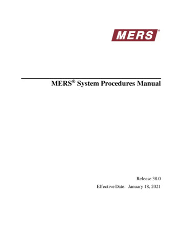
I. Construction and Water Refrigeration Circuit DiagramsA. Construction1. DCM-270BAH(-OS)Top PanelBin Control SwitchBin Top CoverCompressorIce Storage BinDCM-270BAH-OSFront PanelShutterAssemblyPowerSwitchInlet Water ValveControl Box BReservoirCondenserRight Side PanelControl Box ACoverDCM-270BAHFront PanelIcemaking UnitDispensing Water ValveControl Box AAir FilterRight Side LouverDCM-270BAH-OSApron PanelDCM-270BAHApron PanelControl TransformerControl SwitchFuse(AGC-1A, 250VAC)Gear MotorExternal ProtectorControl Board6
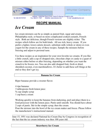
B. Water/Refrigeration Circuit DiagramsDCM-270BAH(-OS)Bin Top CoverBinAgitatorInlet Water ValveWaterSupplyReservoirWater LevelFloatSwitchOverflowEvaporatorBin DrainHoseThermostaticExpansion ValveEvaporator WaterSupply HoseTo DrainGear MotorTo DrainDrain ValveDispense Water ValveDrierFanHigh-Pressure SwitchAir-Cooled CondenserCompressorRefrigeration CircuitWater Circuit7
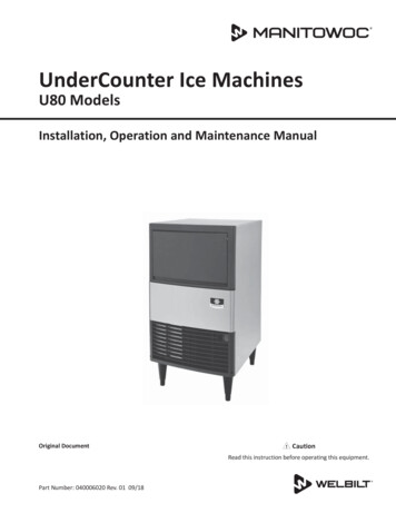
8C. "F-C" Dip Switch8 and 9 "OFF"*1-min. or 5-min.Comp energizedFM energizedGM energizedUFS openLFS openFT starts (90 sec.)WV energizedComp energizedFM energizedGM energized2. Icemaker OffComp energizedFM energizedGM energizedto "2. Ice Purge Cycle" above if UFS closed.to "1. Fill Cycle" above if UFS open.4. IcemakerRestartto "2. Ice Purge Cycle" above if UFS closed.to "1. Fill Cycle" above if UFS open.GM energizedGM de-energized BC closedComp de-energizedFM de-energized3. Icemaker OffBC closed(BC large balance plate disengaged)Ice level lowered3. Icemaker Restart1. Bin Full2. Ice Purge Cycle150-sec. Shutdown Sequence90 sec.60 sec.All Components de-energized6 to 10 sec.1. Bin FullinatesPT termWhen UFS closes,alarm resets and2. Ice Purge Cyclestarts.Legend:BC-bin controlComp-compressorDC-drain cycleDT-drain timerDV-drain valveFM-fan motorFT-fill timer (low water safety)GM-gear motorLFS-lower float switchPT-purge timerUFS-upper float switchWV-inlet water valve1-beep alarm sounds 1-beep alarm continuesWV energizedPT startsGM de-energizedUFS openComp de-energizedFM de-energizedWV energizedGM energizedeeded90 secondsFT excLFS closedUFS closedFT terminatesWV de-energizedComp energizedFM energizedGM energizedMaximum90 secondsLow Water Safety90 sec. FT exceeded1-beep alarm sounds90 sec. PT starts*"F-A" E-0 (G) and Earlier dip switch 8 on - 5 min.*"F-A" E-0 (H) and Later and "F-C" dip switch 8 off - 1 min. and a 2-second periodic agitation was added to occur every 90 min.BC open(BC large balanceplate engaged) BC openBC open(BC large balanceplate engaged)3. Freeze Cycle1-in-1 drain cycle. DV energizes for 2 seconds every hour(S1 Dip Switch 4).RefillDoes not affect operation.A. Sequence of Operation Flow ChartB. "F-A" E-0 (H) and LaterDip Switch 8 "OFF"A. "F-A" E-0 (G) andEarlier Dip Switch8 "ON"2. Bin ControlShutdown & Restart5 sec.To bypass, press the"SERVICE" button afterGM starts.2. Ice Purge CycleLFS closedGM energizedUFS closedFT terminatesWV de-energizedMaximum90 secondsIf Fill 90 sec. FT1-beep alarm soundsWV energizedWhen UFS closesalarm resets and2. Ice Purge Cycle starts.WV energizedFT starts (90 sec.)Power Switch "ON"Control Switch in "ICE""POWER OK" LED on1. Startup1. Fill Cycle4. 1-in-12 Drain Cycle - The factory default is 1-in-1 drain cycle.IMPORTANT! Do not adjust for 1-in-12 drain cycle sequence onthis model."F-A" & "F-C" Control Board Sequence Flow ChartDCM-270B H(-OS)II. Sequence of Operation and Service Diagnosis
B. Service DiagnosisWARNING The appliance should be diagnosed and repaired only by qualified servicepersonnel to reduce the risk of death, electric shock, serious injury, or fire. Risk of electric shock. Use extreme caution and exercise safe electrical practices. Moving parts (e.g., fan blade) can crush and cut. Keep hands clear. CHOKING HAZARD: Ensure all components, fasteners, and thumbscrews aresecurely in place after the appliance is serviced. Make sure that none have falleninto the storage bin. Make sure all food zones in the appliance are clean after service. For cleaningprocedures, see the instruction manual or the maintenance label.1. Ice Production CheckTo check ice production, remove the front, top, and left side panels. Place a containerunder the spout and dispense all ice from the icemaker. Note: The ice dispense switchtimes out after 20 sec. Re-engage every 20 sec. until bin is empty. Move the controlswitch and power switch to the "OFF" position. Remove the bin top cover. Pour warmwater over the remaining ice. After the ice is removed/melted, place the bin top coverin its original position. Do not secure at this time. Remove the control box cover, thenmove the control switch to the "ICE" position and the power switch to the "ON" position.Once the gear motor starts, press the "SERVICE" button on the control board (locatedin the control box). WARNING! Risk of electric shock. Care should be taken not totouch live terminals. Lift the bin top cover and monitor the evaporator extruding head.WARNING! Keep hands, hair, and loose clothing clear of the agitator rotatinginside of the ice storage bin. Once ice begins to fill the bin, start a 10 min. timer. After10 min., move the power switch to the "OFF" position. Place an empty container underthe spout and dispense all ice from the icemaker. Note: The ice dispense switch timesout after 20 sec. Re-engage every 20 sec. until bin is empty. Move the power switch tothe "OFF" position. Weigh the ice to establish the batch weight (minus the weight of thecontainer). Multiply the batch weight by 144 for the total production in 24 hr. Replacethe control box cover and bin top cover in their correct positions and secure. Replace allpanels in their correct positions and secure. Move the power switch to the "ON" positionto start the automatic icemaking process.9
2. Diagnostic ProcedureThe diagnostic procedure is a sequence check that allows you to diagnose the electricalsystem and components. Before proceeding, check for correct installation, adequatewater pressure (10 to 113 PSIG), and proper voltage per unit nameplate.Note: When checking high voltage (115VAC), always choose a neutral (W) wire toestablish a good neutral connection. When checking low voltage (24VAC), always choose a neutral (LBU) wire. When checking control board DC voltage (5VDC), always place the red positivetest lead from the multimeter to CB K5 pin closest to CB K4 connector.See "II.C. Control Board Check." To speed up the diagnostic process, the ice purge cycle may be bypassed bypressing the "SERVICE" button on the control board after the gear motor starts.WARNING! Risk of electric shock. Care should be taken not to touch liveterminals.1) Move the power switch to the "OFF" position, then disconnect the power cord from theelectrical outlet. Remove the front, top, and left side panels. Remove the control boxcover.2) Reconnect the power cord into the electrical outlet, then move the power switch to the"ON" position.3) Move the control switch to the "DRAIN" position. CB "POWER OK" LED and "FLUSH"(drain) LED turns on.Diagnosis "POWER OK" LED: Check that CB "POWER OK" LED is on. If not, checkfor 115VAC at control transformer brown (BR) wire to neutral (W). If 115VAC is notpresent, check the power switch, power cord connection, and breaker. If 115VAC ispresent, check control transformer continuity. Replace as needed. Next, check for24VAC at control transformer red (R) wire to neutral (LBU). If 24VAC is not present,check control transformer continuity. Replace as needed. If 24VAC is present, check24VAC 1A fuse. If fuse is good, check for 24VAC at CB K8 #1 (W/R) to CB K8 #2 (LBU).If 24VAC is present and "POWER OK" LED is off, replace CB.Diagnosis DV: If DV does not energize, check for 24VAC at CB K2 #10 (W/DBU) toneutral (LBU). If 24VAC is not present, check control switch continuity. If open while inthe "DRAIN" position, replace control switch. If closed, check for 0VDC at control boardK9 #1 (W/BK) to K9 #2 (W/BK). If 5VDC is present and control switch is closed, replaceCB. If 24VAC is present, check for restricted DV and DV solenoid continuity. Clean orreplace as needed.3) After all of the water has drained, move control switch to the "ICE" position.10
4) Fill Cycle – "WTRIN" LED is on. WV energizes. The 90-sec. low water safety timerbegins. LFS closes. Nothing occurs at this time. The reservoir continues to fill untilUFS closes, terminating the 90‑sec. low water safety timer, starting the 30‑min. freezetimer, and de-energizing WV. Diagnosis: Check that "WTRIN" LED turns on and waterfills the reservoir. If not, check for water supply line shut‑off valve closed, restrictedwater filters, and restricted WV screen. Next, check for 24VAC at CB K2 #8 (O) toneutral (LBU). If 24VAC is not present, replace CB. If 24VAC is present, turn off thepower switch, disconnect the WV wires and check WV solenoid continuity. If open,replace WV. Reconnect WV wires, move the power switch to the "ON" position, thencheck that DV is not leaking by. Check that WV shuts off when UFS closes.Note: Low Water Safety– If UFS remains open 90 sec. after WV energizes, a 1‑beep
1. DCM-270BAH(-OS) Power Switch Ice Storage Bin Control Box B Right Side Panel Compressor Condenser Control Box A Right Side Louver Air Filter Control Box A Cover DCM-270BAH Front Panel DCM-270BAH-OS Front Panel DCM-270BAH-OS Apron Panel Control Switch Gear Motor External Protector C