Transcription
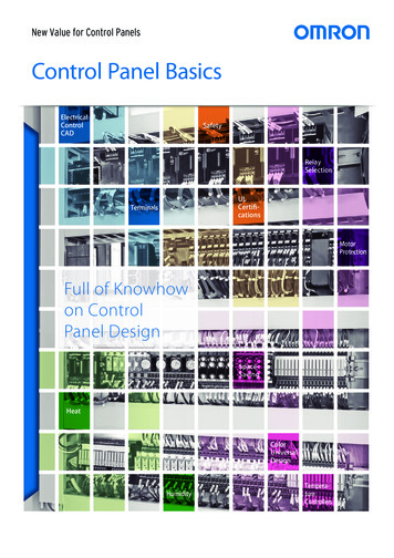
New Value for Control PanelsControl Panel rtificationsTerminalsMotorProtectionFull of Knowhowon ControlPanel emperatureControllers
2Basic Information onControl Panel DesignKnowhow on Control Panel Design, from the Latest Information,Environmental Measures, Safety Standards, and Valuable Information.Changes in the market require handling a wide variety of control panel issues.Control Panel Basics describes OMRON’s wealth of knowhow and information and provides easy-to-understanddescriptions of the knowledge required to solve these issues through concrete examples.
3Control Panel BasicsCONTENTSDesignEfficiencyControl Panel Efficiency Starts with the TerminalsP.4Application of Electrical Control CADP.6Panel Assist WebP.8Change from Tightening Screws to Inserting WiresWays to Increase the Efficiency and Quality of Electrical Control DesignsUseful Tool to Simplify and Accelerate Panel DesigningEnvironmentalMeasuresHeat MeasuresP.10High Humidity MeasuresP.12Examples of and Measures to Prevent Motor FailuresP.14Knowhow on Fan Selection and Installation to Prevent Device Failure Caused by HeatMeasures against Short-circuits Caused by Condensation from High HumidityMachinePrecautionsProtective Measures in Advance to Minimize the Effects of FailuresRelay Selection:“Better Too Big Than Too Small” Does Not ApplyP.16Optimum Selection Techniques to Improve Relay Circuit ReliabilityStandardsTypes of UL CertificationP.18Control Panel Design ConsideringElectrical Safety StandardsP.20Difference between UL Listed Components and UL Recognized ComponentsPoints on Panel Design for Conformance to IEC 60204-1ReferenceSaving Space in Control Panels with No Transformers P.22Eliminating Transformers for Control PanelsColor Universal DesignP.24Display Innovations for On-panel DevicesP.25Color Designs That Are Easy to Use by AnyoneIncreased Visibility with White Characters on Black Backgrounds
4 Control Panel BasicsDesignEfficiencyControl Panel Efficiency Startswith the TerminalsChange from Tightening Screws to Inserting WiresYou Can Increase Production Efficiency by Rethinking Wiring WorWiring WorkWiring work is essential to manufacturing control panels, and it accounts for the majority of the lead time for control panel manufacturing.Therefore, if you can make wiring work easier and faster, you can dramatically shorten the manufacturing lead time for control panels.Current IssuesNormally when people hear about wire connection methods, many of them tend to think about securing wires by tightening screws.And in reality, many of the control devices used in control panels use screw terminals, and such devices have become common.Also, screw terminals have a long track record, are the method most recognized by customers, and are therefore considered reliable.However, screw terminals require that you loosen the screw, attach the wire (crimp terminal), and then tighten the screw, which is a lot of work.New Screwless ConnectionsScrewless connections, which have recently become common in Europe, eliminate the need to tighten screws to dramatically reduce the workrequired for wiring and they are gradually becoming popular in control panels around the world.The work of loosening and tightening screws has been replaced by merely inserting wires to complete wiring work, greatly reducing work time.First you need to learn about screwless connections and then experience how efficient this method is.Push-in TerminalsPush-in terminals are one type of screwless terminal. Wiring is completed simply by inserting a wire with a crimped ferrule.The strength of a spring presses the ferrule against the terminal wall to connect the wire.MechanismClamp springDifferences in Wiring WorkWiringScrew terminals(1) Loosen the screw. (2) Remove the screw. (3) Attach the terminal. (4) Tighten the screw.Round terminals27 s *Forked terminals7s *UnnecessaryConductive fittingThe pressure of the clampspring holds the ferrule securely.Push-in terminalsInsert.2s *FerrulesNo Retightening WorkNote: Test conditions: IEC 60947-7-1Not necessaryNot necessaryNot necessary* Based on OMRON demonstration test results.
5What Are Push-In Plus Terminal Blocks?Push-In Plus Terminal Blocks were independently developed by OMRON for easy wire insertion and firm wire holding ability.It’ s as easy as inserting an earphone jack: No tools are required for wiring.Easy to InsertHeld Firmly in PlaceOMRON’s Push-In Plus terminal blocks are as easy as insertingEven though less insertion force is required, the wires are heldto an earphone jack. This reduces the load on worker fingers.firmly in place. The advanced mechanism design technologyand manufacturing technology produced a spring that ensuresbetter workability and reliability.IEC standardPush-In PlusScrew terminalblock20 N min.125N112N(cable diameter) terminal block(AWG20、0.5mm2 )* Information for Push-In Plus terminal blocks and Screw terminal blocksis based on OMRON's actual measurement value data for the XW2R.Work with Both HandsWiring Possible with Stranded WiresOptimized shape to hold the screwdriver was created by the resin partsYou can insert wires with ferrules or you can also insert solidand the spring. Work goes smoothly when connecting stranded wireswires or stranded wires.directly to the terminal because it’s easier to aim at the desired terminal.Stranded wiresFerrulesSolid wireRecommended Products with Push-In Plus TerminalsUninterruptiblePower Supply(UPS)S8BASwitch ModePower SuppliesS8VK-SMeasuring andMonitoring RelaysK8DTSolid-state TimersH3DTSockets for Relays withCommon SoketsForcibly Guided Contacts(for MY/H3Y(N)-B)(for G7SA)PYF-PU(-L)P7SA-PUPushbutton SwitchesPush-In PlusTerminal Block SeriesA22N-P/A30N-P/M22N-PSolid-state TimersH3Y(N)-BCommon Sokets(for G2R-S/H3RN-B/K7L-B)P2RF-PUSlim I/O RelaysG2RV-SRSolid State Relaysfor HeatersG3PJPower MonitorsKM-N2/KM-N3Solid-state TimersH3RN-BSlim I/O RelaysG3RV-SRDIN TrackTerminalBlockXW5TLiquid LeakageSensor AmplifiersK7L-BI/O Relay TerminalsG70VDigital TemperatureControllersE5CC-B/E5EC-B
6 Control Panel BasicsDesignEfficiencyApplication of Electrical Control CADElectrical Control CAD Significantly Increases the Efficiency and Qualityof Electrical Control DesignsWhat Is an Electrical Control CAD?Electrical control CAD is specialized software to design circuit diagrams (elementary wiring diagrams),cable production diagrams, and control panel layout diagrams. Specialized electrical CAD previously existed,but CAD that unifies management of design data have recently received a lot of attention.Realtime Information Linkage between Diagrams *Circuit DesignsControl Panel DesignSpecifications CoordinationConceptual ConsiderationsCable and Harness DesignCentral DatabaseLists* This illustration is based on the functionality of the E3. series from Zuken Inc.The use of high-quality electrical control CAD libraries is importantto maximizing the functionality of electrical control CAD.Partners for electrical control CAD:Zuken Inc.EPLANE3.series is a product name of Zuken Inc. for their Electrical and Control Cable Design Solution.EPLAN is a registered trademark of EPLAN Software & Service GmbH & Co. KG.
7Benefits of Introducing Electrical Control CADAutomatic Creation of Diagrams and ListsThe unified management of design information in a database makes it easy to automatically create diagrams,such as cable production diagrams, as well as many different types of lists.Reduced Design WorkAutomatic designing greatlyreduces the work required tocreate diagrams and lists.CurrentSituationWiththe CADReduction in Total Design Work by Up to 30% to 50% *Reduction of 50% to 70% for Cable Production Diagrams *CollectingCheckingspecifications information oncomponentsCircuitdesigningCollecting LibraryCheckingregisspecifications information oncomponents trationCircuitdesigningCable designingCheckingdiagramsOutputtingBOMChecking ReleasingCabledesigning diagrams ngReduction achieved with the CAD* Example for Zuken E3.series.Achieve Consistency between Diagrams in RealtimeThe results of designing work (circuit diagrams, cable production diagrams, control panel layout diagrams, terminal block layout diagrams,connector lists, etc.) can be edited from any diagram and the changes will be reflected in all the related diagrams and lists in real time.This helps eliminate entry mistakes and forgotten corrections to greatly increase design quality.Higher Design QualityCurrent SituationWith the CADBy eliminating entry mistakes andforgotten corrections from diagrams,Designinformationhigher quality is achieved inCentralDatabasediagram data and reworking aftermanufacturing is eliminated.Flexible Panel Design, Including Wiring, Interference Checks, and Wire ProcessingSimplified 3D designing allows you to consider interference checks and prohibited areas in designs.Wire length measurement function allows wires to be prepared in advance.Greater ManufacturingEfficiencyMore efficient designing isaccompanied by more efficiency inpanel manufacturing preparations,assembly, and installation.Panel Information Calculations Wire processing information Wire, component, and in-paneltool lists Number ofterminal connectionsNote: The example of the results of CAD introduction on this page is based on the functionality of the E3. series from Zuken Inc.
8 Control Panel BasicsDesignEfficiencyPanel Assist WebSimplify and Accelerate Panel Designing.Information to Solve Your Control Panel Manufacturing IssuesThe Panel Assist Web is a new website for our customers that work with control panels.You can select products and search for documents. Or you can find solutions for theissues you face in control panel manufacturing and you can manage BOM. Use thiswebsite to more efficiently design control panels.Take a Look Now!www.ia.omron.com/solution/panel/Easy Product Selection: No Registration RequiredSolution Display ExamplesFind Information toHelp SolveIssuesYou can find information to help you solve control panel issues, suchas downsizing or work reduction issues.(e.g., explanatory videos for Push-In Plus Terminal Blocks are available.)Sample: Specifications SearchEasy Selectionof In-panel DevicesYou can greatly reduce model selection work.You can filter selection by model and then compareproduct specifications for easy selection.Sample: Recommendation DisplayFind Information withoutGetting LostJust the right products and documents will be recommended inresponse to operations. You can find the information you needquickly and select the optimum products.It can beadded to BOM
9Even More Convenient Functions with Member Registration (Free Registration)BOM ExampleCreate BOM EasilyYou can create and save BOM of OMRON and non-OMRON products.Convenient tools are provided for more-advanced designing.BOM toReduce Design WorkYou can use the tool and various kinds of convenient functions starting from BOM.Checking in Advance with Thermal Simulation ToolReduce Work with the Terminal Block Support ToolThe electrical specifications andapplicable wires are automaticallydisplayed for the selected devices.You can easily select the Terminal Blocksrequired to wire devices without wastingtime.BOM ExampleJust input basic control panel informationin addition to the selected deviceinformation to understand heat risks andthereby reduce the need of working later.Replacement with the Latest ProductsDownload Documents as Soon as You Select PartsYou can import an existing BOM to check productmanufacturing status and stock status, and to replaceproducts with the most suitable up-to-date products.You can download CAD data or catalogsin multiple languages.
10 Control Panel BasicsEnvironmentalMeasuresHeat MeasuresThe correct Fan must be selected to suppress temperature rise inside the panel.If the temperature inside the panel increases, the lives of devices and parts inside the panel will be reduced and malfunctions could result.Particularly devices and parts that generate heat are greatly affected by heat.Panel cooling and Fan selection are extremely important to long-term usage of the panel and parts inside the panel.Selecting Fans1Check the heating values of devices and the panel (kW).Check the heating value of each device located in the control panel and then find the total heating value.Generally speaking, the heating value indicates the power consumption, so you can assume that the power consumption equals the heating value.Heating value (W) Input power Output powerOutput power Output powerEfficiency2ΔT of devices and panel: Allowable temperature rise ( C)ΔT T2 T1ΔT can be obtained by subtracting the device ambient temperature, T1from the allowable internal temperature, T2.Note: As a guideline, you can make the calculation with a value of 10 C.(Use the more severe condition.)ΔT 10 C34Calculate Q, the required flow rate (m3/min).Q T1Source ofheat(guideline)50 WΔTT2m3/minQ Flow rate (m3/min)ΔT Allowable temperature rise ( C)W Heating value (kW)Select the size of the required Fan based on the maximum flow rate.Normally, select a Fan with a maximum flow rate of 1.3 to 2 times the calculated required flow rate (Q).As the flow rate increases, noise increases. If the Fan is used in an environment where noise is a problem, select a Fan with a lower flow rate.5Selecting OptionsIf fine foreign matter may enter the Fan, select a Filter.If slender objects such as fingers may enter the Fan, select a Finger Guard.Note: Actually results may vary from calculations, so measurement and confirmation in the actual panel are required.Calculation Example for a Control Panel with Two 100-W Power SuppliesNote: The S8JX-N10024C (output voltage: 24 VDC, output current: 4.5 A, efficiency: 83% min.) is used for the 100-W Power Supplies.First, the heating value (power consumption) is calculated.Heating value (W) 24 (V) 4.5 (A) 24 (V) 4.5 (A)83 (%)108 (W) 108 (W) 22.120 (W)0.83Two Power Supplies are used, therefore,22.12 (W) 2 44.2 (W) 0.04 (kW)Q: Required flow rate 50 0.04 (kw)Maximum flow rate calculation: Q 2ΔT: 10[ C] 0.2 [m3/min]0.2 2 0.4 [m3/min]Therefore, one R87F-A A83H is required according to the maximum flowrate of the table on the right.Note: This calculation example assumes that the control panel containsonly two Power Supplies.Models and Maximum Flow rateModel A15HPR87F-A A13HPR87F-A A93HPR87F-A A85HPR87F-A A83HR87F-APoint!Maximum flow rate (m3/min)Size (mm)50 Hz60 Hz120 120 t 382.73.1120 120 t 251.92.292 92 t 250.91.080 80 t 380.80.980 80 t 250.60.7If the flow rate is insufficient, two Fans can be operated inparallel for approximately twice the maximum flow rate.Q1 2 Q2Q1: Flow rate of one FanQ2: Flow rate for parallel operation
11Airflow Direction and Inlet/Outlet Cooling Effect DifferencesWhen the Heat-generating Portions AreConcentrated at One LocationReference Information:The Fan airflow is in one direction,which is indicated on the top of the Fan.When the Heat-generating Portions Areat Many LocationsFan rotation directionHeatgenerationAirflow directionHeatgenerationHeatgenerationInletairflow directionHeatgenerationAdvantages of Inlet InstallationAdvantages of Outlet Installation- You can concentrate cooling onthe heat-generating portions.- The pressure inside the box increases,which reduces dust entry from other openings.- A wide area can be cooled.Fan rotationdirectionOutletairflow directionRecommended Axial FansR87F AC Axial FansSize[mm]Large120 120 t 38R87F-A A15HP120 120 t 25R87F-A A13HP92 92 t 25R87F-A A93HP80 80 t 38R87F-A A85HP80 80 t 25R87F-A A83HFlow (3.1)Optionsat 50 Hz(at 60 Hz)ModelsPlug with CableFinger GuardsFiltersPlug with CableFiltersFinger Guard R87F-PC(JT) R87F-FL (S)R87F-FG* Required for models with terminals(models ending with "P").Search for OMRON R87F for details.
12 Control Panel BasicsEnvironmentalMeasuresHigh Humidity MeasuresIf a control panel is installed in a location with high humidity,measures against short-circuits are required.Condensation will occur in the control panel as the result of a difference in the device temperature and external air temperature.This condensation may adhere to a PCB and if condensation and dust repeatedly collect on the PCB, short-circuits will occur.Examples of Short-circuits Caused by CondensationCase 1: Short-circuit from Water Drops Generated by CondensationCase 2: Short-circuit Caused by Repeated Condensation and Dust CollectionAgingFacilities essing ScheduleMorningFacilities operated.Facilitiesstopped.Condensation will occur if there is a difference between the temperature resultingfrom device heat generation and the air temperature while the facilities are stopped.Preventing Short-circuits with Products with Coated PCBs or ModificationsCoatingPCBs can be coated to protect them againsthumidity and reduce the possibilityof short-circuit accidents.Recommended Products with Coated PCBsSwitch ModePower SuppliesS8VK-SS8FS-GMicro sH7CXH7E -N Ask your OMRON representative for more information on coating.Digital Temperature Controllers E5 C/E5E5CB C-BSingle-phase Power ControllerG3PWSearch for OMRON with the model name .
13MEMO
14 Control Panel BasicsMachinePrecautionsExamples of and Measuresto Prevent Motor FailuresImplementing Protective Measures for Failures of Important DevicesIn general, when devices are used for a long period of time, they deteriorate over that time, and ultimately fail.To minimize the effects of device failure, we recommend that you implement protective measures in advance for important devices.This section discusses motors, which are important devices.MotorsA motor converts electrical energy to mechanical energy.Due to its characteristics, a motor has both an electrical structure and a mechanical structure , and it fulfills very important roles.Electrical energyMotorMechanical energyThere are various failure types that lead to motor failure.By detecting abnormal signals and using them to stop the motor, motor failure and damage to the motor’s load can be avoided.Major examples of motor failures and products that can be used to detect motor abnormalities are introduced on the right-hand page.One Point !Are just breakers and thermal relays insufficient as protective measures?Not all types of motors and operation can be protected with just breakers and thermal relays.General thermal relays can not detectphase loss during operation,so operation may not be stable.Example:Breakers can not detect phase loss.Disconnection
15Motor Failure Examples (Phenomena)Phase-loss ErrorsFailure to startBurning due to phase-loss operationUnstable operationExample:Disconnection of a power line A motor does not start. A motor cannot operate a load. Forced startup causesa motor to burnout. Stopping of operation when the load is heavy. Intermittent starting and stopping, etc.Phase loss when startingCausesWelded contactsinside a breakerPhase loss during operationDisconnection Wheels rolling over or people stepping on lines Cables bent too far, etc.BreakerPhase loss inside a motorLoose screws(contact failure in wiring)Inside a motorTerminalWeldingReversed-phase (Phase-sequence) ErrorsReverse rotation of motor willdamage valves in pumps.Incorrect wiring causesreverse rotation of the motor.Incorrect wiring Movable equipment Incorrect phase on power line sideOverloadsCaught foreign matterlocks up the motor.Current LeakageConveyorlocked.Current leakage dueto insulationdeteriorationForeign matterRecommended Protective RelaysDetect Phase loss andPhase sequenceModels added withtransistor outputs forstable operation with PLC.Phase-sequencePhase-loss RelaysK8DT-PHNon-return valves・Aged deterioration・Deterioration due towater or oil intrusion
16 Control Panel BasicsMachinePrecautionsRelay Selection:“Better Too Big Than Too Small” Does Not ApplyCircuit Reliability will be Increased by Selecting a Suitable Relay for the Load.With a computer or smartphone, you may want to select a hard disk or memory with extra capacity.In general, something larger often works well to substitute for something smaller, as in the saying "better too big than too small".However, that does not work with relays. The structural conditions required in a control relay to carry a large current as opposed toa minute current are different, so a suitable relay must be selected.Selecting a suitable relay will help increase the reliability of the relay circuit.You need to understand relay characteristics and correctly select relays to increase the quality of control circuits.Relay Selection MethodsSwitching High-capacity LoadsSwitching Minute LoadsAn important thing that determines the contact breaking capacity isTo reduce the probability of contact failure, using bifurcated contactsthe size of the gap between contacts of the same pole. Double-break(see right-hand page) with two contact points is more effective thancontacts (see right-hand page) with a wide gap are effective. An Agusing single contacts with one contact point. Also, the arcs that arealloy with high conductivity is generally used for the contact material.generated when switching minute loads are small, so they do notHowever, Ag alloys are not suitable to switch minute loads that do notremove oxide and other films. Therefore, Au or Au alloys that resistgenerate arcs when switching because organic films easily forms oncorrosion are used for the contact material.the contact surfaces.However, they are not suitable to switch large currents due to thesmaller contacts and lower conductivity in comparison with Ag alloys.Differences and Trends in Contact MaterialsAg alloyAu-clad ContactsAg alloys have high conductivity and are effective in switching largeThe contact surfaces are clad with Au, which has a high resistance toloads. Some corrosion occurs, but the switching arcs have a cleaningcorrosion, to increase resistance to corrosion. The formation of aeffect that removes organic films that form on contact surfaces.resistive film will be suppressed, and arcing will be also reduced tomake these contacts effective for minute loads.Au claddingAg AlloyAg alloyCu alloyCu alloyHighLowNote: Au: Gold, Ag: Silver, Cu: Copper.Switching capacityResistance to corrosionLowHigh
17Differences in Contact Configuration and Application ExamplesContact ConfigurationDouble-break contactsCommon LoadsHigh-capacity loadsGuideline: Loads over 15 AApplication ExamplesHigh capacitySwitching compressors and heatersControl applications for switching motorsNote: For relays, 40 A for AC and 10 A for DC.Single contactsGeneral loadsGuideline: 0.05 to 15 AMoving contact Fixed contactGeneral sequence circuitsContact imageBifurcated contactsMoving contact Fixed contactMinute loadsPLC inputs, signal applications,Guideline: Less than 0.05 Aand self-holding circuitsContact imageCrossbar Bifurcated ContactsMinute loadsGuideline: Less than 0.01 AMoving contact Fixed contactContact imageNote: Contact reliability is increased becausenearly line contact is achieved and theweight per surface area is larger.Alarm applications(Infrequent applications)Low capacityMajor Examples of Relay Models, Contact Configuration, and Contact MaterialsRelays forControl CircuitsModelHigher Load Capacity(2) MKEven Higher Load Capacity(3) MM(1) MYSingleMKSingleAg alloy(3) MMSingleAg alloy(4) MY(S)Single2-pole: Ag alloy4-pole: Au cladding Ag alloy(5) MK-SSingleAg alloy(6) MY4ZBifurcatedAu cladding Ag alloy(7) MY4Z-CBGCrossbar bifurcatedAu cladding Ag alloy(8) MYQBifurcatedAu plating Ag alloy(9) MY4HBifurcatedAu plating Ag alloy(10) MY2KSingleAu plating Ag alloy(11) G7KSingle(1)MYAu plating Ag alloy(12) MKKSingleGreater Contact Reliability(Minute Loads)(6) MY4ZEven Greater ContactReliability (Minute Loads)(7) MY4Z-CBGGreater Resistanceto Environments(8) MYQResistance toCorrosive Gases(9) MY4HHolding Circuits(10) MY2KMechanicallyHeld Relays(11) G7KHigh-capacity DC LoadSwitching(14) MK-S(X)Ag alloy(13) MMKSingleAg alloy(14) MK-S(X)Double breakAg alloy(15) MMXSingleAg alloy(16) G2R- -SSingleAg alloy(17) G2R- -SSingleAg alloy(18) LYSingleAg alloy(19) G7JDouble breakAg alloy(20) G7ZDouble breakAg alloy(21) MMXSingleAg alloy(22) MK-S(X)Double breakAg alloy(23) G2RV- -APSingleAu plating Ag alloy(24) G7T for inputCrossbar bifurcatedAu cladding Ag alloy(2)Higher Load Capacity(5) MK-SHigher Load Capacity(12) MKKEven HigherLoad Capacity(13) MMKLarge Number of Poles(15) MMXSlim Relays(16) G2R- -SNote: Mainly Two-pole Relays are used in control circuits.Relays forI/O ApplicationsHigh AC Capacity(18) LYHigh DC Capacity(21) MMXEven Higher Capacity(19) G7JEven Higher Capacity(22) MK-S(X)Even Higher Capacity(20) G7ZTypes of Terminal RelaysTerminal Relays (4 Points)(17) G2R- -SMinute Loads(23) G2RV- -APSlim Design(25) G7TNote: Mainly One-pole Relays are used for I/O applications.Even Higher Reliability(24) G7TEven Slimmer Design(26) G2RV(27) G6B-4BND/4CB(28) G6D-F4BI/O Blocks(8 or 16 Points)(29) G70V-SI Series(30) G70V-SO Series(31) G7TC-I Series(32) G7TC-O Series Contact materials2-pole: Ag alloy3-pole: Ag alloy4-pole: Au cladding Ag alloy(For Relay Sequences)Circuit Operation Confirmation(4) MY(S)Contact configuration(25) G7T for output SingleAg alloy(26) G2RV SRSingleAg alloy(27) G6B-4BNDSingleAg alloy(27) G6B-4CBSingleAg alloy(28) G6D-F4BSingleAg alloy(29) G70V-SI Series SingleAu plating Ag alloy(30) G70V-SO Series SingleAg alloy(32) G7TC-O Series SingleAg alloy(31) G7TC-I Series Crossbar bifurcated Au cladding Ag alloy
18 Control Panel BasicsStandardsTypes of UL CertificationThere are UL Listing and UL Component Recognition for UL certification.UL certification is required for control panels used in the USA.Here we describe the difference between certification as a UL listed component (listing) and certification for a UL recognized component (R/C).Actions Required for New or Revised Components Used in Control Panels for the USAIndustrial control panels used in the USA are required to comply with UL508A.Of the components used in control panels that comply with UL 508A, there are differences in the requirements dependingon the UL certification (UL listed components or UL recognized components).UL 508A ComplianceUsing UL Listed ComponentsApplication to the UL is notrequired.Using UL Recognized ComponentsApplication to the UL is required. If urgent changes to components become necessary foradjustments or to handle problems, they can be made immediately. These components must be registered. The documents and datarequired for registration must be prepared and an applicationmust be made to the UL. The UL will check the certification conditions and process the changes,so time will be required to use new or upgraded components.Changes are possible at any time.Component registration is required, which delays application. New or upgraded components can be used at any time.OK !WAIT !
19There are also differences based on whether the component is directly connected to devices orequipement outside of the control panel.Example in Final Installation Site of Control PanelUsing UL Listed ComponentsUsing UL Recognized ComponentsWiring is allowed.Wiring is not allowed.Device/EquipmentDevice/EquipmentNote: There are some exceptions.Point !For People Who Want to Know MoreUL ListingUL Component Recognition In general, this certification applies to end products that are operatedby general users, such as machine tools, robots, and other equipment This certification applies to components that are built into endproducts that do not function by themselves or have limitedthat are directly controlled by an operator.functionality (molded products, wires, PWB, and general-purpose Because it is assumed that the equipment will be used by anoperator or a general user, there are many restrictions and evaluationtests for designs and configuration components.Automation Systems). Components for which UL Listing is not required fall underUL Component Recognition.Recommended UL Listed ComponentsA Perfect Fit for Small Control PanelsCoated PCBs for Better Resistanceto Environment Connections forEasy WiringReliable and Easy OperationWorldwide Power SupplyResistant in tough environmentsEasy and fast installationThe most compact class onthe marketWorldwide 3-phase Power SupplyResistant in tough environmentsEasy and fast installationThe most compact class onthe marketSwitch Mode Power SuppliesSwitch Mode Power SuppliesSwitch Mode Power Supplies(60-W, 120-W, 240-W, 480-W)(15-W, 30-W, 60-W, 120-W,240-W, and 480-W models)(120-W, 240-W, 480-W,and 960-W models)S8VK-SS8VK-GS8VK-TSearch for “OMRON S8VK-S” for details.Search for “OMRON S8VK-G” for details.Search for “OMRON S8VK-T” for details.
20 Control Panel BasicsControl Panel Design ConsideringElectrical Safety StandardsStandardsThe IEC 60204-1 electrical safety standards relatedto machine control panels must be considered.The power supply breakers, device locations, and electric-shock prevention for control panel design are described from the viewpoint of safety standards.Power Supply Cutoff(Breaker) Devices- ON “ ” and OFF “Power Supply Cutoff (Breaker) Devices” must be indicated.- There must be an external operation means (e.g., handle).- There must be a means to lock the device in the OFF position.- There must be a suitable cutoff capacity. Etc.Device Locations(1) Power supply cutoff devices: 0.6 to 1.9 m, recommended max.: 1.7 m(2) Manual operation devices: 0.6 m or higher(3) Terminals: 0.2 m or higher(4) Devices that must be approached for periodic maintenance or adjustments: 0.4 to 2.0 mEnclosure Degree of Protection: IP22 or BetterElectric ShockP
Useful Tool to Simplify and Accelerate Panel Designing Panel Assist Web P.8 CONTENTS Control Panel Basics Application of Electrical Control CAD Ways to Increase the Efficiency and Quality of Electrical Control Designs P.6 Heat Measures Knowhow on Fan Selection and Installation to Prevent
