Transcription
Concord 4 Installation GuideContentContact information 1Description 1Panel location 2Power and wire length 2Mounting the panel 3Programming 4Sensor group characteristics 7Specifications 9Regulatory information 9Table 1: Panel capabilitiesCapabilitiesConcord Express v4Concord 4/ConcordCom mercial v4Zones3296Partitions26Bus devices1616User codes16230Table 2 below describes the basic panel (out-of-box)hardware capabilities for all panels:Contact informationFor contact information, see www.utcfireandsecurity.comor www.interlogix.com.For technical support, toll-free: 888.437.3287 in the USincluding Alaska, Hawaii, Puerto Rico, and Canada.Outside the tool-free area, contact your dealer. 2016 UTC Fire & Security Americas Corporation, Inc.Interlogix is part of UTC Climate Controls & Security, aunit of United Technologies Corporation.All rights reserved.DescriptionTable 2: Panel hardware capabilitiesPow erInput for an AC step-down, plug-in styletransformer.Auxiliary pow eroutputOutput that supplies 9 to 14 VDC w ith up to 1amp for bus devices and hardwired detectors,such as smoke and motion detectors.Bus A and BInput and output that provides communicationbetw een bus devices and the panel.Siren driverOutput that can drive an 8-ohm load and providesintrusion and fire alarm sounds for partition 1 (6w atts maximum).Tw o onboardoutputsCan be used to activate other signaling devicesbased on system events. Out 1 is a 9 to 14 VDCsource output, limited to 1.0 amp maximum. Out2 is an open-collector output, rated up to 14 VDC,300 mA maximum.Microphone inputInput used for tw o-way audio w hen used inconjunction w ith the Interrogator 200 audioverification module.Eight supervisedhardw ired zonesInputs for various hardwired detectors. Zone 8can be set up in programming to accept tw o-wiresmoke detectors. It sources 9 to 14 VDC, 90 mAmaximum.Built-in RFreceiverAllow s use of up to 96 or 32 319.5 MHz crystaland/or SAW learn mode w ireless sensors andtouchpads.This is the Installation Guide for the following Concord 4control panel models: 600-1021-95R Concord 4 RF 600-1022-95R Concord Express V4600-1040 Concord Commercial V4600-1042 Concord HybridThis manual provides information for installing a basicUL Listed Fire and Security System. To modify or use forother purposes, visit the UTC Fire & Security website foradditional instructions and training.Table 1 below shows the standard panel capabilities.P/N 466-2371 REV D ISS 19JUL161
Phone lineconnectionAllow s panel to communicate w ith centralmonitoring station and/or pagers.Note: The total current sourced from all terminals cannotexceed 1 amp.Panel locationBefore permanently mounting the panel, use thefollowing guidelines to choose a mounting location. To help reduce wire run lengths and labor, centrally locatethe panel with relation to detection devices wheneverpossible.Locate the panel where the temperature will not exceed120ºF (49ºC) or fall below 32ºF (0ºC). To prevent wire runs from picking up electrical noise,avoid running wires parallel with electrical wiring or fixturessuch as fluorescent lighting. Mount the panel at a comfortable working height.Leave at least 24 inches in front of the panel to open thecabinet door and access the panel.Leave space to the left and right of the panel for wiring,phone jack, and mounting optional modules.Leave at least 9 inches above the panel cabinet for antennas.Power and wire lengthThe panel can supply up to 1 amp (1,000 mA) in full loadalarm condition for system devices connected to panelterminals 4 ( 12V), 7 and 8 (speaker terminals), 9(OUT1), 11 ( 12V), 24 (2W SMK ZONE 8), andSnapCard terminals.For 24-hour backup, the total standby current draw for alldevices connected to panel terminals 4 ( 12V), 9(OUT1), 11 ( 12V), 24 (if configured for two-wire smokeloop), and SnapCard terminals is limited to 90 mA(during normal standby condition) using a 4.5 or 5.0 Ahbattery, or 190 mA (during normal standby condition)using a 7.0 Ah battery.The total system wire length allowed can vary dependingon devices powered by the panel, the wire lengthbetween devices and the pane, and the combined wirelength of all devices.Table 3 below describes the maximum wire lengthallowed between compatible devices and the panel, andthe minimum and maximum current draw of each device.2Table 3: Wire length requirementsDeviceMax. w irelength topanelStandby Alarm m Am A draw drawSuperBus 2000 2x16 LCDalphanumeric touchpad22 ga.: 300 ft.18 ga.: 750 ft.15 mA90 mASuperBus 2000 ATP 1000alphanumeric touchpad22 ga.: 300 ft.18 ga.: 750 ft.12 mA110 mASuperBus 2000 ATP 2100alphanumeric touchpad22 ga.: 300 ft.18 ga.: 750 ft.30 mA165 mASuperBus 2000 ATP 2600alphanumeric touchpad22 ga.: 300 ft.18 ga.: 750 ft.30 mA165 mASuperBus 2000 GTS 5022 ga.: 100 ft.18 ga.: 250 ft.270 mA300 mASuperBus 2000 fixed display 22 ga.: 300 ft.touchpad18 ga.: 700 ft.11 mA65 mASuperBus 2000 FTP 1000fixed display touchpad22 ga.: 300 ft.18 ga.: 700 ft.12 mA75 mASuperBus 2000 RFtransceiver22 ga.: 1,000 ft. 45 mA18 ga.: 2,500 ft.55 mASuperBus 2000 RF receiver22 ga.: 1,100 ft. 35 mA18 ga.: 2,800 ft.35 mA1SuperBus 2000 phoneinterface/voice module22 ga.: 40 ft.18 ga.: 120 ft.25 mA600 mASuperBus 2000 voice-onlymodule22 ga.: 40 ft.18 ga.: 120 ft.20 mA300 mA(jumper)600 mA (nojumper)SuperBus 2000 2 amppow er supplyN/ANo loadNo load4 input/2 output SnapCardN/A20 mA185 mA18Z hardw ired zoneexpander SnapCardN/A38 mA230 mA14 output SnapCardN/A1 mA130 mA1SuperBus 2000 8Z inputmodule22 ga.: 1,800 ft. 18 mA18 ga.: 4,000 ft.35 mASuperBus 2000 4-relayoutput module22 ga.: 350 ft.18 ga.: 900 ft.180 mASuperBus 2000 energysaver module22 ga.: 1,600 ft. 20 mA18 ga.: 4,000 ft.20 mASuperBus 2000 cellularbackup moduleStandard90 mApow er 22 ga.:15 ft. 18 ga.:40 ft. High90 mApow er 22ga.: 10 ft. 18ga.: 30 ft.1600 mASuperBus 2000 automationmodule22 ga.: 1,500 ft. 30 mA18 ga.: 4,000 ft.35 mASuperBus 2000 w irelessgatew ay-ready kit22 ga.: 40 ft.18 ga.: 90 ft.1600 mAInterrogator 20022 ga.: 3,200 ft. 10 mA18 ga.: 4,500 ft.12 mA65 mA1900 mA10 mAConcord 4 Installation Guide
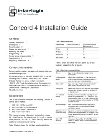
DeviceMax. w irelength topanelStandby Alarm m Am A draw drawInterrogator AVM22 ga.: 110 ft.18 ga.: 260 ft.45 mA300 mATw o-wire smoke detectors(429AT, 429C, 429CT,521B, 521BXT, 521NCSXT22 ga.: 330 ft.18 ga.: 330 ft.70 uA60 mATw o-wire smoke detectors(system sensor 2400,2400TH)22 ga.: 330 ft.18ga.: 330 ft.120 uA80 mAHardw ired interior siren (13949)22 ga.: 750 ft.0 mA18 ga.: 1,500 ft.85 mA150 mASpeaker siren (60-528 or13-060)500 mA0 mAWire requirementsSuperBus 2000devices4-conductor, 22- or 18-gaugeInterrogator 200 AVM 4-conductor, 22-gauge, shieldedpow er and microphoneTw o-wire smokedetectors2-conductor, 22-gauge, 330 ft. max.2-conductor, 18-gauge, 830 ft. max.Mounting the panelMount the panel to the wall or wall studs.Piezo dynamic exterior siren 22 ga.: 750 ft.0 mA(13-060)18 ga.: 1,500 ft.18 ga.: 100 ft.Device1Maximum current draw for the SnapCards does not include the loadw hich may be applied to their auxiliary DC supply.Note: When installing SuperBus 2000 RF receivermodules, the antenna tamper feature must be set to off.Caution: Make sure you are free of static electricitywhenever you work on the panel with the cover open. Todischarge any static, first touch the metal panel chassis,and then stay in contact with the chassis when touchingthe circuit board. We recommend using a groundingstrap.To mount the panel:Table 4 below describes the total system wire lengthsallowed for all SuperBus 2000 devices when installingsystems using unshielded or shielded cable. Themaximum wire length for individual devices is showninstable below.1.Remove the panel door and remove the necessarywiring knockouts. Be careful not to damage thecircuit board.2.Feed all wires through wiring knockouts and placethe panel in position against the wall.Table 4: Total system wire lengths3.Level the panel and mark the top and bottommounting holes.Wire typeTotal system w ire18-gauge, unshielded4,000 ft.4.Install anchors where studs are not present.18-gauge, shielded3,000 ft.5.22-gauge, unshielded4,000 ft.Partially insert screws into the two top mounting holelocations, then hang the panel on the two screws.22-gauge, shielded3,000 ft.6.Recheck for level, insert the two lower screws, andtighten all four mounting screws.After determining panel location, run all necessary wiresto that location using the guidelines in Table.Figure 1 below shows the main component locations.Figure 1: Panel com ponentsTable 5: Device w ire requirementsDeviceWire requirementsAC pow er transformer2-conductor, 18-gauge, 25 ft. max.Earth groundSingle conductor, 16-gauge solid, 25 ft. max.Telephone (RJ-31X)4-conductorDetection devices2- or 4-conductor, 22-gauge, 1,000 ft. max.2- or 4-conductor, 18-gauge, 2,500 ft. max.(based on 30 ohms max. loop resistanceincluding device)SpeakersAntennasMounting holeEPROMProgrammingtouchpadheaderMounting holeSnapcardconnectorBatteryterminalsTerminal stripMounting holes2-conductor, 18-gauge, 100 ft. max.Concord 4 Installation Guide3
The display shows SYSTEM PROGRAMMING.Grounding the panelFor maximum protection from lightning strikes andtransients, connect the enclosure to earth ground. Use16-gauge, solid copper wire from an earth grounded coldwater pipe clamp to the enclosure. For best results, werecommend that you crimp a spade lug on the wire endat the panel and secure the lug to the enclosure.Antenna shroudsInstall a plastic antenna shroud (included with the panel)over each antenna and snap them into the holes on topof the enclosure (skip this step for hybrid andcommercial systems).ProgrammingFor onsite system programming, you must have analphanumeric touchpad.You must use an installer/dealer code (default 4321) toenter program mode. You may place the system intoprogramming mode only when you disarm all partitions.Note: If the system is powered up after the programmingtouchpad is connected or if a bus command scan isexecuted, the programming touchpad will be learned(programmed) into the system and must later bemanually deleted.To enter program mode:7.After programming is complete, disconnect thetouchpad from the panel header.Touchpad programming optionsIn program mode, touchpad buttons let you navigate toall installer programming menus for configuring thesystem.Table 6 below describes the touchpad button functionsin program mode.Table 6: Touchpad programming functionsButtonProgramming function#Select menu item or data entry.*Deselect menu item or data entry (if pressedbefore #).A ( )Scroll through available option at the currentmenu tier. Scroll through sensor text optionsduring sensor text programming.B ( )CEnter pauses w hen programming phonenumbers.DDelete certain programming settings.0 to 9Enter numeric values w herever needed.1 and 2Select off (1) or on (2) w herever needed.1 to 6Press and hold to enter alphabetical characters Athrough F for account numbers.7 and 9Press and hold to enter * (7) or # (9) for phonenumbers.1.Make sure you disarm the system in all partitions.2.Press 8, 4321, 0, 0.Menu navigationThe display shows SYSTEM PROGRAMMING.There are two basic tiers of programming menus, tier 1and tier 2.To enter program mode using a programmingtouchpad:1.Connect the red, black, green, and white wires fromthe programming touchpad cable (60-791) to thepower and bus wires/terminals on an alphanumerictouchpad, matching the 12V (red), Bus A (green),Bus B (white), and GDN (black) on each.2.Make sure the system is powered up and disarmed.3.Connect the plug on the cable onto the panelprogramming touchpad header.4.Press 8, 4321, 0, 2.The touchpad sounds one short beep.5.Press * and verify that the display shows SERVICETOUCHPAD ACTIVE.6.Press 8, 4321, 0, 0.4From the tier 1 System Programming menu, you canaccess the following tier 2 programming menus: SecurityPhonesPhone optionsTimersLight controlsTouchpad options ReportingSiren optionsSensorsAudio verificationAccessory modulesOnboard optionsMacro keysConcord 4 Installation Guide
Only when the display shows SYSTEM PROGRAMMINGcan you advance to tier 2 programming menus.Press B or # to advance forward through menus. PressA or * to move backward through the menus.Only when a specific menu is displayed can youadvance to those menu settings. For example, from theSENSORS display, pressing # gives you access tolearning sensors, programming sensor text, deletingsensors, and viewing/editing sensor programming.SensorHow to trip the sensorHandheld w irelesstouchpadsPress the BYPASS button.Key fobs *Press and hold the lock and unlockbuttons together until the key fob LEDflashes.ELM key fobs *Press and release the unlock button tw icequickly, then press and hold until the LEDflashes three times.Press and release the unlock button oncequickly, then press and hold until the LEDflashes two times.To exit program mode:1.Press * until the display shows SYSTEMPROGRAMMING.2.Press A or B until the display shows EXITPROGRAMMING READY.3.Press # and the touchpad displays the time anddate.Sensors menuThe Sensors menu gives you access to the followingsettings: Learn sensors. Add (learn) hardwired zones, wirelesssensors, and wireless touchpads into panel memory.Sensor text. Name the sensors and zones you haveadded to the system.Delete sensors. Delete zones and sensors from panelmemory.Edit sensors. View or change a sensor group or partitionassignment. You can also identify whether a zone iswireless or hardwired, whether it is configured as normallyclosed (NC) or normally open (NO), and whether the zonePress and hold the unlock button until theLED flashes once.* Key fobs have not been investigated by UL for use in a UL Listedinstallation.Learn sensorsThe default setting is “None”.The panel comes with factory programmed onboardhardwired zones. Install 2 kohm, end of line (EOL)resistors on all unused factory sensors shown above andhardwired zones. If you don’t want to install EOLresistors, delete any unused zones from memory. SeeTable on page 6 for onboard hardwired zone factoryprogramming. Sensors must be placed in a partition orsensor group. To change the sensor group or partitionassignment after adding a sensor or zone, use the EditSensors menu.To add (learn) sensors into panel memory:1.The display shows LEARN SENSORS.is a touchpad.Table 7 below describes how to trip different types ofsensors to program (learn) them in the panel.With the display showing SENSORS, press #.2.Press #.The display shows SENSOR PTN 1.Table 7: Tripping sensors3.Press # to select partition 1 or press 2, 3, 4, 5, or 6and then press # to select the desired partition.SensorHow to trip the sensorThe display shows SENSOR GROUP 0.Hardw ired zonesStart w ith the zone in its normal state, andthen trip the zone into its alarm state. Anormally closed door, for example, shouldbe closed w hen you begin the learnsensors process. To trip the zone, openthe door.Wireless sensorsFollow the instructions included w ith eachsensor.Wireless door/w indowsensors with externalcontactsPlace the external contact in the alarmcondition, and then activate the sensortamper sw itch.Self-actuated bellsActivate the tamper sw itch.Concord 4 Installation Guide4.Enter the sensor group and press #. (See Table fora description of all sensor group characteristics.)The display shows TRIP SENSOR nn, where nn isthe displayed (next available) sensor number.5.To change the displayed sensor number, enter thedesired sensor number and press #.The desired sensor number is displayed.6.With the desired sensor number displayed, use theguidelines in Table 6 to force the sensor or zone you5
are adding (learning) into the panel memory to senda signal to the panel.7.8.To add another sensor to the same sensor groupand partition, repeat the process.To add sensors to another sensor group or partition,press * twice and repeat the process.Table 8 below describes the factory default zone inputs.3.Cycle through the menus as shown in Table 9below.Table 9: Quick programming menu structureAccount numberPartition number 1 to 6Account number 00000CS phoneCS phone 1CS phone noneCS phone 2Table 8: Zone factory programmingCS phone noneZone inputGroup num ber and description110 - entry/exit217 – instant interior follow er313 – instant perimeter413 – instant perimeterSensor group 0513 – instant perimeterTrip sensor number 1 to 96613 – instant perimeter713 – instant perimeter813 – instant perimeterCS phone 3CS phone noneLearn sensorsSensor partition number 1 to 6End programmingIf the panel memory is cleared, all onboard hardw ired zone factoryprogramming w ill be cleared.Quick programming modeUse the quick programming mode to program basicsystem programming with a SuperBus 2000 fixed displaytouchpad, SuperBus 2000 FTP 1000 touchpad, or anySuperBus 2000 alphanumeric touchpad. The followingmenus are accessible: Account number (all partitions)SC phone 1CS phone 2CS phone 3 Learn sensors (limited to selecting sensor number, sensorgroup, and partition assignment). An alphanumerictouchpad is required for programming sensor text instandard programming mode.Use the A and B buttons to toggle across main menusand use the # and * buttons to toggle up and downthrough the submenus.To enter quick programming mode:1.Make sure the system is disarmed in all partitions.2.Press 8, enter the installer/dealer code, and thenpress 03.The display shows ACCOUNT NUMBER.6Concord 4 Installation Guide
Sensor group characteristicsTable 10 below shows what the sensors on your Concord 4 system do. Every sensor is assigned to a group, and thistable specifies those groups and functions. Every device must be assigned to one of these groups.Note: The “X” marks in the table represent characteristics present in a group.Table 10: Sensor group characteristicsNum ber Nam eApplicationAlarmDelay00Fixed panic24-hour audible fixed r audible portable emergency PolicebuttonsInstant02Fixed panic24-hour silent fixed r silent portable emergencybuttonsSilentInstant04Fixedauxiliary24- hour auxiliary sensor, such aspendant panic or holdup buttonAuxiliary Instant05Fixedauxiliary24-hour auxiliary emergency button,siren shutoff confirms CS reportAuxiliary Instant06Portableauxiliary24-hour portable auxiliary alertbutton07Portableauxiliary08RestoralSupervisor CSyreportXChim e(level)Active(level)X1, 2, 3X1, 2, 3X1, 2, 3X1, 2, 3XX1, 2, 3XX1, 2, 3Auxiliary InstantX1, 2, 324-hour portable auxiliary button,siren shutoff confirms CS reportAuxiliary InstantX1, 2, 3SpecialintrusionSpecial belongings, such as guncabinets and w all safesPoliceInstantXXX1, 2, 309SpecialintrusionSpecial belongings, such as guncabinets and w all safesPoliceStandardXXX1, 2, 310Entry/exitdelayEntry and exit doors that require astandard delay timePoliceStandardXXXX2, 311Supplementary Garage doors and entrances that1,5Extended Delay require extended delay timePoliceExtendedXXXX2, 312Supplementary Drivew ay gates and entrances thata tw ice extended delay timeExtended Delay require1,5PoliceTw iceextendedXXXX2, 3X2, 3X13InstantperimeterExterior doors and w indowsPoliceInstantXXX14InstantinteriorInterior doors (hardwired)PoliceFollowerXXX2, 315InstantinteriorInterior PIR motion sensors 1 (RFw ireless)PoliceFollowerXX2, 316InstantinteriorInterior doors (hardwired)PoliceFollowerXX317InstantinteriorPIR motion sensors 1 (RF w ireless)PoliceFollowerXX318InstantinteriorInstant interior cross-zone # PIRmotion sensors 1, 2PoliceFollowerXX3Concord 4 Installation GuideX7
Num ber Nam erior doors that initiate a delaybefore going into alarm 1PoliceInteriorX20DelayedinteriorPIR motion sensors that initiate adelay before going into alarm 1PoliceStandard21Local instant 24-hour local alarm zone protectinginterioranything that opens and closesPoliceInstantXX1, 2, 322LocaldelayedinteriorPoliceStandardXX1, 2, 323Local instant 24-hour local alarm zone protectingauxiliaryanything that opens and closes 3Auxiliary InstantXX1, 2, 324Local instant 24-hour local alarm zone protectingauxiliaryanything that opens and closes,sirens shut off at restoral 1Auxiliary InstantXX1, 2, 325LocalspecialchimeNotify the user w hen a door isopened, sounds emit from a localannunciator 1SpecialchimeInstantX1, 2, 326Fire24-hour fire, rate-of-rise heat, andsmoke sensorsFireInstantXX27OutputmoduleHardw ired output module (HOM)lamp control or other customerfeatures 3SilentInstantXX1, 2, 328OutputmoduleHOM, PIR motion sensor, soundsensor, or pressure mat 3SilentInstantX1, 2, 329AuxiliaryFreeze sensorAuxiliary Instant32OutputmoduleHOM, PIR motion sensor, soundsensor, or pressure mat 3SilentInstant33SirenWireless siren supervisionSilentInstant34GasCarbon monoxide (CO) gasdetectors 3Auxiliary Instant35Local instant Local alarm levels 1 and 2, report topolice (dayCS in level 3zone)Police38Auxiliary1.2.3.4.5.8Same as group 21, plus activationinitiates a delay before going intoalarmWater sensor 3XSupervisor CSyreportChim e(level)Active(level)XX3XX3XXX1, 2, 31, 2, 31, 2, 3XX1, 2, 3XXX1, 2, 3InstantXXX (level 3only)1, 2, 3Auxiliary InstantXXX1, 2, 3This group is not certified as a primary protection circuit for UL-listed systems and is for supplementary use only.Sound instant police siren if tw o or more sensors are tripped w ithin 4 minutes. Otherw ise sensors are followers to delayed sensors. IfAlarm Verification is on, group 18 functions like group 17.This group has not been investigated by UL.This group is required for UL-listed residential fire alarm applications.Does not satisfy Auto Stay Arming exit requirement.Concord 4 Installation Guide
SpecificationsPow er requirementsClass 2, 16.5 VAC, 40 VA, 60 Hz (600-1023 or600-1024)Rechargeable battery: 12 VDC, 4.5 or 5.0 Ahlead-acid (60-681) or 12 VDC, 7 Ah (60-680).The battery w ill last 24 hours w ith no AC andspecified stand-by load.Auxiliary pow eroutput1.0 A at 9 to 14 VDC (12 VDC typical)Radio frequency319.5 MHzNominal RF range1,000 feet (305 m) typical open airStorage temperature-30 to 140ºF (-34 to 60ºC)Operatingtemperature32 to 120ºF (0 to 49ºC)Maximum humidity85% relative humidity, noncondensingDimensions (H x W xD)14 x 12 x 3 in. (35.6 x 30.5 x 7.6 cm) Hardwired magnetic contact (13-068 or 13-071) orwireless learn mode door/window sensor (60-362) Immediate beeps set to on.UL 98 options set to on.Receiver failure set to on (if wireless devices are used).Siren verify set to on.Exit delay set to 60 seconds.Quick exit set to off. Siren timeout set to 4 minutes or more.Entry delay set to 45 seconds or less.RF TX timeout set to 24 hours (if sys tem includes built inreceiver or SuperBus 2000 RF receiver or SuperBus 2000RF transceiver and wireless burglary sensors).Extended delay set to off. Sleep time set to off.Two trip error set to off.Alarm verify set to off.Disable trouble beeps set to off.Household fire warning system (UL 985)Regulatory informationUL listed installationsThis section describes the requirements for UL listedinstallations.Basic system: Control panel (600-1021-95R Concord 4 RF, 600-102295R Concord Express V4, 600-1040 Concord CommercialV4, or 600-1042 Concord 4 Hybrid).Standard class 2 16.5 VAC, 40 VA power transformer 22145 or 22-156 (600-1023), 22-156-CN, or 22-145-CN(600-1023-CN), or power line carrier class 2 16.5 VAC, 40VA power transformer 22-149 (600-1024) or 22-149-CN(600-1024-CN). You must order these transformersseparately from UTC Fire & Security. Basic system plus the following: Wireless smoke sensor 60-506-319.5, 60-848-02-95, orTX-6010-01-1 learned into sensor group 26.Immediate beeps set to on. UL 98 options set to on.Receiver failure set to on (if wireless devices are used).Siren verify set to on.Sleep time set to off.Siren timeout set to 4 minutes or more.Two-trip error set to off. Disable trouble beeps set to off.RF TX timeout set to 4 hours (if system includes built inreceiver or SuperBus 2000 RF transceiver and wirelesssmoke sensors).UL 1023 and 985 24-hour backupBackup battery 12 V 4.5 or 5.0 Ah (60-681) or 12 V 7 AH(60-680).SuperBus 2000 fixed display touchpad (60-820), FTP1000 (600-1020), 2x16 LCD touchpad (60-746-01), ATP1000 (60-983), ATP 2100 (60-985), ATP 2600 (60-984),2x20 LCD touchpad (60-803), or 2x20 VFD touchpad (60-For 24-hour backup, the total current draw for allconnected devices is limited to 90 mA (during normalstandby conditions) using a 4.5 or 5.0 Ah battery, or 190mA (during normal standby conditions) using a 7.0 Ahbattery.804).Interior speaker siren (60-528), hardwired interior siren(13-949), or speaker siren (13-060).Basic system but also include a SuperBus 2000 RFreceiver (60-764-95R-01) or a SuperBus transceiver (6001025-01-95R).SIA system requirementsHousehold burglary alarm system unit (UL 1023)Basic system plus the following:Concord 4 Installation GuideSIA system requirements are the same as thosedescribed for a UL-listed basic system. If multipleannunciation is required, use additional touchpads. Thisapplies to model numbers 60-746-01, 60-803, 60-804,60-820, 60-983, 60-984, 60-985, and 600-1020. ULrequirements take priority over SIA requirements.Table 11 on page 10 describes programmingrequirements to meet ANSI-SIA CP-01.9
Table 11: SIA setting requirementsFunctionDefault settingRequired settingExit extensionOnOnDuress codeDisabledDisabledDialer abort delay30 seconds15 to 45 secondsCancel messageOnOnCall w ait cancelDisabledOn if reporting tocentral station andcustomer has callw aiting service.Entry delay30 seconds30 to 240 secondsExit delay60 seconds45 to 184 secondsSwinger limit11Smoke verifyOffOn if smoke alarmsare programmed intosystem.Cross zoneDisabledEnabled for zonesw ith high probability offalse alarmsTable 12 below describes nonprogrammable (hardcoded) system operation, as required to meet ANSI-SIACP-01 and is provided only for your reference. UL approved bell/housing, such as Ademco #AB12M orequivalent. Immediate beeps set to on.UL 98 options set to on.Receiver failure set to on (if wireless devices are used).RF TX timeout set to 4 hours.24-hour tamper set to on.System tamper set to on. Automatic phone test set to on.Phone text frequency set to 1.Next phone test set to 1.Siren verify set to on.AC failure set to on.Exit delay set to 120 seconds or less. Quick exit set to off.Two-trip error set to off.Alarm verify set to off.Disable trouble beeps set to off.Phone number must be programmed.High level reports set to on. Low level reports set to on.Communication failure set to on.Extended delay set to off.Sleep time set to off.Siren timeout set to 4 minutes or more.Table 12: ANSI-SIA CP-01 requirementsFunctionSIA false alarm1OperationUL 1610 24-hour backupEnabledSame as UL 1023 and 985.Auto stay armingEnabledDisarm during entry delayEnter code only (or 1 CODE)Cancel alarmEnter code only (or 1 CODE).Abort annunciationEnabledExit errorEntry/exit progress annunciationEnabled2EnabledNotes:1. Auto Stay Arming is attached to "Standard" entry/exitdelays. (Please refer to table 10,"delay" column).2. You may use the silent arming feature to suppressarming level and exit beeps for the current armingperiod. Refer to the Concord 4 user manual for moreinformation on silent arming.Commercial burglary alarm system unit (UL 1610)Basic system using control panel 600-1040, SuperBus2000 RF transceiver module (600-1025-01-95R), plusthe following: Hardwired magnetic contact (13-068 or 13-071) orwireless learn mode door/window sensor (60-499).SAW PIR sensor (60-639-95R), crystal PIR sensor (60-UL 1635 digital alarm communicator systemFor UL 1635 installations, entry delay plus dialer abortdelay must not exceed 60 seconds. Same as UL 1023,985, and 1610 plus: AC failure set to on.Phone number must be programmed.Low CPU battery set to on.Next phone test set to 1. Phone test frequency set to 1.High level reports set to on.Low level reports set to on.Communication failure set to on.RF TX timeout set to 4 hours.Central station reportingThe panel has been tested with the following centralstation receivers using SIA and Contact ID reportingformats: 703-95R), or DS924i PIR sensor (60-511-01-95). 10CS-5000 central station receiverSur-Gard central station receiver with models SG-DRL2Aand SG-CPM2Osborne Hoffman central station receiverConcord 4 Installation Guide
Note: The installer must verify the compatibility betweenthis panel and the central station receivers being used.UL Canada listed installationsThis section describes the requirements for CUL (ULCanada) listed installations.Residential burglary alarm system unit (ULC subjectC1023-1974)Basic system as described for UL 1023 listedinstallations plus: Hardwired magnetic contact (13-068 or 13-071) orwireless learn mode door/window sensor (60-362) Siren timeout set to 5 minutes or moreuses, and can radiate radio frequency energy and, of notinstalled and used in accordance with the instructionmanual, may cause harmful interference to radiocommunications. However, there is no guarantee thatinterference will not occur in a particular installation.If this equipment does cause harmful interference toradio or television reception, which can be determinedby turning the equipment off and on, the user isencouraged to try to correct the interference by one ormore of the following: Reorient or relocate the receiving antenna. Increase the separation between the equipment andreceiver.Connect the affected equipment and the panel receiver toseparate outlets, on different branch circuits.Consult the dealer or an experienced radio/TV technicianfor help. Residential fire warning system control unit (ULCS545-M89) Basic system as described for UL 985 listed installationsplus:Part 68. This equipment complies with Part 68 of theFCC rules. Located on this equipment is a label thatcontains, among other information, the FCC registrationnumber and the ringer equivalence number (REN) forthis equipment. If requested, this information must beprovided
such as fluorescent lighting. Mount the panel at a comfortable working height. Leave at least 24 inches in front of the panel to open the cabinet door and access the panel. Leave space to the left and right of the panel for wiring, phone jack, and mounting optional modules. Leave at le