Transcription
STRENGTH OFMATERIALSForMECHANICAL ENGINEERINGCIVIL ENGINEERING
STRENGTH OF MATERIALSSYLLABUSStress and strain, elastic constants, Poisson's ratio; Mohr’s circle for plane stress andplane strain; thin cylinders; shear force and bending moment diagrams; bending andshear stresses; deflection of beams; torsion of circular shafts; Euler’s theory of columns;energy methods; thermal stresses; strain gauges and rosettes; testing of materials withuniversal testing machine; testing of hardness and impact strength.ANALYSIS OF GATE PAPERSMECHANICAL1 Mark 2 MarkExam Year Ques. Ques. 8202009226201012520114310201233920132142014 Set-12382014 Set-23272014 Set-32262014 Set-42262015 Set-13252015 Set-225122015 Set-31132016 Set-134112016 Set-224102016 Set-32382017 Set-154132017 Set-23472018 Set-145142018 Set-22410Exam 14 Set-12014 Set-22015 Set-12015 Set-22016 Set-12016 Set-22017 Set-12017 Set-22018 Set-12018 Set-2CIVIL1 Mark 2 MarkQues. Ques. 12262263648226149137125 Copyright Reserved by Gateflix.in No part of this material should be copied or reproduced without permission
CONTENTSTopics1.Page NoSIMPLE STRESS AND AIN ENERGY AND IMPACT LOAD112556777899113.2.1 Strain EnergyGate Questions29313.13.23.33.43.53.63.7BENDING STRESS AND SHEAR STRESS34353737373739464.1 Pure Bending Moment4.2 Beam under Uniform Strength4.3 Direct Shear StressGate Questions495051544.5.IntroductionStresses and StrainsTypes of stress and strainHook’s law and Elastic PropertyTrue Stress and True StrainElastic ConstantsTypes of MaterialsStrain Under Tri Axial LoadingAxial Stress in Compound BarsElongation of the Taper Beam under Axial LoadElongation Due to Self-Weight of the BodyThermal StressGate QuestionsSHEAR FORCE AND BENDING MOMENT DIAGRAMShear Force and Bending MomentBeamFree Body DiagramMethod of AnalysisEquations of EquilibriumExample ProblemsSpecial Case of Shear Force Diagram and Bending MomentGate QuestionsPURE TORSION Copyright Reserved by Gateflix.in No part of this material should be copied or reproduced without permission
5.15.25.35.46.Pure TorsionComposite ShaftsSpringConnection of SpringsGate Questions7071737677IntroductionNormal Stress and Shear StressPrincipal Planes and Principal StressMaximum Shear Stress Plane and Maximum Shear StressPrincipal Strain and Shear strainCombined Bending & TorsionMohr’s circleGate Questions8888888889899091IntroductionTypes of ColumnSlenderness ratioLoad analysis of columnPressure vesselGate QuestionsSLOPE AND DEFLECTION95959595961008.1 Introduction8.2 General Expression8.3 Methods for Slope &Deflection8.4 Special Case of Slope and Deflection107107107109COMBINED STRESS AND STRAIN6.16.26.36.46.56.66.77.8.9.COLUMN AND PRESSURE VESSEL7.17.27.37.47.5ASSIGNMENT QUESTIONS10. CIVIL GATE QUESTIONS Copyright Reserved by Gateflix.in No part of this material should be copied or reproduced without permission114126
1SIMPLE STRESS AND STRAIN1.1 INTRODUCTION1. ENGINEERING MECHANICSThe engineering mechanics may be definedas a branch of applied mechanics that dealswith behaviors of solid bodies subjected tovarious types of loadings. This is usuallysubdivided into further two streams i.eMechanics of rigid bodies or simplyMechanics and Mechanics of deformablesolids. The mechanics of deformable solidsis known by several names i.e. strength ofmaterials, mechanics of materials etc.2. MECHANICS OF RIGID BODIESThe mechanics of rigid bodies is concernedwith the static and dynamic behavior underexternal forces of engineering componentsand systems which are treated as infinitelystrong and under formable primarily wedeal here with the forces and motionsassociated with particles and rigid bodies.Mechanics of rigid bodies is further dividedin to two subdivision i.e. kinematics ofmechanics and dynamics of mechanics.the stresses, strains, andproduced by loads.1.2 STRESSES AND STRAINSdeflections1. STRESSAs we know that in mechanics ofdeformable solids, externally applied forcesacts on a body and body suffers adeformation. From equilibrium point ofview, this action should be opposed orreacted by internal forces which are set upwithin the particles of material due tocohesion. These internal forces give aconcept of stress. Therefore, let us define astress.Let us consider a rectangular bar of somecross – sectional area and subjected to someload or force.Let us imagine that the same rectangular baris assumed to be cut into two halves atsection XX. The each portion of thisrectangular bar is in equilibrium under theaction of load P and the internal forcesacting at the section XX has been shown3. STRENGTH OF MATERIALSStrength of material is branch of mechanicsthat concerns with study of the forces andits effect on the properties of the deformedbody. It is concerned with the internalforces and associated changes in thegeometry of the components.Particular objective of SOM is that whetherthe components fail by breaking in service,and the amount of deformation they sufferis acceptable. Therefore, the subject ofmechanics of materials or strength ofmaterials is central to the whole activity ofengineering design. Usually the objectives inanalysis here will be the determination ofThe stress can be defined as total internalresistance per unit area of the component.But after removal of the load, body regainsits original position, so total internalresistance should be equal to applied load.So stress can be given by,PStress ( σ ) AThe basic units of stress are N / m2 (or Pa),N/mm2, MPa, GPa. Copyright Reserved by Gateflix.in No part of this material should be copied or reproduced without permission
MPa 106 PaGPa 109 PaKPa 103 Pacompressive stresses are considered asnegative.2. STRAINIf a bar is subjected to a direct load and bodySome times N / mm2 units are also used,is deformed body there will be deformationbecause this is an equivalent to MPa.under action of load. If the bar has anFor direct stresses, if area underoriginal length L and changes by an amountconsideration is original area, then it isδL, The strain produce is defined as followsknown as Engineering stress or nominalChange of length δL Strain ( ε ) stress or simply stress. But, if the areaOriginal lengthLtaken is actual area at the time ofconsidering the stress, then stress is knownas true stress.PPNominal Stress ; True Stress AAoWhere, Ao Original area of specimen.A Actual area of specimen.Proof Stress:When a material such as Aluminum does nothave an obvious yield point and yetundergoes large strains after theproportional limit is exceeded, an arbitraryyield stress may be determined by the offsetmethod.A line parallel to initial linear part is drawn,which is offset by some standard amount ofUnit of Strain:Strain is a measure of the deformation of thematerial and is a non dimensional Quantity.It is simply a ratio of two quantities with thesame unit. So strain is dimension lessquantity.Sign convention for strainTensile strains are positive whereascompressive strains are negative.1.3. TYPES OF STRESS AND STRAINStrain such as 0.2%. The intersection of theoff set point (A) defines the yield stress oroff set yield stress, which is slightly abovethe proportional limit and is called proofstress.1. TYPES OF STRESSAccording to direction of loading, Stress canbe divided into following way:Sign convention for stressTensile Stresses or pulling Stresses areconsideredaspositivewhereas Copyright Reserved by Gateflix.in No part of this material should be copied or reproduced without permission
Stress produced due to load in the form ofbending moment or eccentric axial load isknown as bending stress. Nature of bendingstress is tensile and compressive.Shear stress (τ )Normal stress ( σ )We have defined stress as force per unitarea. If the stresses are normal to the areasconcerned, then these are termed as normalstresses. The normal stresses are generallydenoted by a Greek letter ( σ ).Tensile or compressive stressesThe normal stresses can be either tensile orcompressive whether the stresses act out ofthe area or into the area.Let us consider now the situation, where thecross – sectional area of a block of materialis subject to a distribution of forces whichare parallel, rather than normal, to the areaconcerned.Such forces are associated with a shearing ofthe material, and are referred to as shearforces. The resulting force per unit area isknown as shear stress.The resulting force intensities are known asshear stresses, the mean shear stress isgiven byShear Stress τ Axial Stress (σ a )Stress produced due to load acting along theaxis of the component is called as axialstress. It may be tensile or compressive innature.PAxial Stress AoWhere, Ao Original area of specimenPAWhere P is the total force and A the areaover which it acts.2. TYPES OF STRAINAccording to basis of the deformation, straincan be classified asBending Stress (σ b ) Copyright Reserved by Gateflix.in No part of this material should be copied or reproduced without permission
Normal Strain ( ε )Deformation produced under the action ofthe load in the direction of the load is calledas linear or normal strain. In normal strain,dimension of the body changes but theshape of the body remains same.Longitudinal StrainThe linear deformation in the direction ofthe load is known as the longitudinaldeformation. It may be tensile andcompressive in nature depend upon thenature of the loading.Longitudinal Strain ( ε x )Change of length δL Original lengthLLateral StrainThe linear deformation in perpendiculardirection of the load is known as the lateraldeformation. It may be tensile andcompressive in nature depend upon thenature of the longitudinal Strain.Change of diameterδDLateral Strain ( ε y ) Original diameterDVolumetric StrainIt is the ratio of total change of the volumeto the original volume of the component.Change of volumeVolumetric Strain ( ε v ) Original volumeε v -When a body is subjected to shearingstresses, the shape of the body getsdistorted. The measurement of thisdistortion is done by angle of distortion.Under pure shear the shape of the body getsdistorted but the volume remains same.shear stressModulus of rigidity, ( G ) shear strainτG γAs we know that the shear stresses actsalong the surface. The action of the Stress isto produce or being about the deformationin the body considers the distortionproduced shear strain on an element orrectangular block.If under the shear, the shear strain is γ thenthe linear strain in the diagonal of thespecimen is given by.γεd i.e. Linear strain of diagonal is half of2the shear strain in the body.3. STRAINSECTIONSFORDIFFERENTCROSSa) Rectangular Co- ordinatesLet us consider a rectangular block of lengthL, width D and thickness t. after applicationof load P in x direction change in dimensionis dL, dD and dt respectively. The strainproduced in x- direction is given bydVVChange of length dL (εx )Original lengthL Every longitudinal strain is associatedThe strain produced in y- direction is givenwith two lateral strains.by Longitudinal strain and lateral strain areopposite in nature.Change of width dW εy ) (Original widthWShear strain:The strain produced in z- direction is givenby Copyright Reserved by Gateflix.in No part of this material should be copied or reproduced without permission
Change of thickness dt Original thicknesstThe volume of the rectangular body is givenbyV LwtTaking the log in both sides anddifferentiating the equation, volumetricstraindV dL dw dtεV VLwtε V ε x ε y ε z(εz )b) Cylindrical co-ordinatesLet us consider a cylinder of length L,diameter. After application of load P in xdirection change in dimension is dL, dDrespectively. The strain produced in x and ydirection is given byChange of length dL(εx ) Original lengthLChange of diameter dD(εr ) Original diameterDVolume of the cylinder is given byπV D2 L4Taking the log in both sides anddifferentiating, we get volumetric strainεV dV dLdD 2 ε l 2ε cVLDc) Spherical co-ordinatesLet us consider a sphere of diameter D. Afterapplication of load P in x direction change indiameter is dD respectively. Volumetricstrain produced in spherical body is givenbydVdDεV 3 3εcVD1.4 HOOK’S LAW & ELASTIC PROPERTYis removed. According to Hook’s law, Up toproportional limit stress is directlyproportional to strain. Stress strainStress Const. EStrainThis constant is given by the symbol E and istermed as the modulus of elasticity orσYoung's modulus of elasticity E εThe unit of modulus of elasticity is MPa. Curve 1 represents actual or true stressstrain diagram. Curve 2 represents theoretical stressstrain diagram. Hooke s law is valid up to limit ofproportionality. However for mild steel,Proportional limit and Elastic limit arealmost equal, but for other metals &materials elastic limit may be higherthan proportional limit, for exampleRubber.1.5 True stress and True Strain1. True stress: The true stress is definedas the ratio of the load to the cross section areaat any instant(σ ) Tload σ (1 ε )Instantaneous areaWhere σ and ε is the engineering stress andengineering strain respectively.1. HOOKE’S LAWA material is said to be elastic if it returns toits original, unloaded dimensions when load Copyright Reserved by Gateflix.in No part of this material should be copied or reproduced without permission
2. True Strain:L( ε ) dll TLo L ln ln (1 ε ) L0 ( ε ) ln AA 2ln dd T 00 OR engineering strain ( ε ) eεT - 1The volume of the specimen is assumed to beconstant during plastic deformation Q A 0 L0 AL .It is valid till the neckformation.Where,Ao & A are original & final arearespectively.Lo & L are original & final lengthrespectively.Note: Comparison of engineeringand the true stress-strain curvesshown below The true stress-strain curve is also knows asthe flow curve. True stress-strain curve gives a trueindication of deformation characteristicsbecause it is based on the instantaneousdimension of the specimen. In engineering stress-strain curve, stressdrops down after necking since it is based onthe original area In true stress-strain curve, the stresshowever increases after necking since the crosssectional area of the specimen decreasesrapidly after necking.The flow curve of many metals in the region ofuniform plastic deformation can be expressedby the simple power law.σ f K ( ε T )nWhere K is the strength coefficientn is the strain hardening exponentn 0 for perfectly plastic solidn 1 for Elastic solidFor most metals, 0.1 n 0.51.6 ELASTIC CONSTANTS:1. Poisson’s ratio (μ)It has been observed that for elasticmaterials, the lateral strain is directlyproportional to the longitudinal strain. Theratio of the lateral strain to longitudinalstrain is known as the poison's ratio.Poisson ratio ( μ ) -Lateral Strainlongitudinal Strain2. Modulus of rigidity(G)Up to proportion limit, shear stress isdirectly proportional to shear strain.Shear stress (τ)αshear strain(γ)Shear stress ( τ ) G shear strain(γ)G shear strain(γ) γ Shear stress ( τ ) τ Copyright Reserved by Gateflix.in No part of this material should be copied or reproduced without permission
G is known as shear modulus and its unit issame as the unit of stress i.e. MPa.3. Bulk Modulus(K)Up to proportional limit, the hydrostaticstress is directly proportional to volumetricstrain.dVdP VdPK dVVK is known as bulk modulus and its unit isMPa.Note: RELATIONSHIP BETWEEN ELASTICCONSTANTSLinear stressLinear strainShear stressModulus of regidity, G shear strainDirect stressBulk mod ulus, K Volumetric strain1LateralstrainPoisson s ratio, µ mLinear strainYoung s mod ulus, E 1 E 2G 1 2G(1 μ)m elastic properties are the same at everypoint in the body. However, the propertiesneed not to be the same in all the directionfor the material to be homogenous.Isotropic materials have the same elasticproperties in all the directions. Therefore,the material must be both homogenous andisotropic in order to have the lateral strainsto be same at every point in a particularcomponent.2. ISOTROPIC MATERIALIf the response of the material isindependent of the orientation of the loadaxis of the sample, then we say that thematerial is isotropic or in other words wecan say that isotropy of a material is acharacteristics, which gives us theinformation that the properties are thesame in the different direction, on the otherhand if the response is dependent onorientation it is known as anisotropic.1.8 STRAIN UNDER TRI AXIAL LOADINGIf a rectangular block is subjected to threenormal stresses σx, σy & σz on all its faces,mutually perpendicular to each other in x, y& z directions respectively as shown in fig. 2 E 3K 1 - 3K(1 - 2μ) m E 9KG3K Gµ 1 3K 2G m 6K 2G1.7 TYPES OF MATERIALSThen volumetric strain of the specimen isgiven byεV εx εy εZ σx σ y σz εv [1 2µ ]E A material is homogenous if it has the samecomposition throughout body. Hence the1.9 AXIAL STRESS IN COMPOUND BARS1. HOMOGENEOUS MATERIAL Copyright Reserved by Gateflix.in No part of this material should be copied or reproduced without permission
Case (a):Let the axial load is applied on thefree end of the member as shown in fig.Then the load shared by each memberP1 P2 P3 PDeformation produced in member 1 is givenbyPl14Pl1 δ1 A1E1 πd12 E1Deformation produced in member 2 is givenbyPl24Pl2 δ2 A 2 E 2 πd 2 2 E 2Deformation produced in member 1 is givenbyPl34Pl3 δ3 A 3 E 3 πd 32 E 3Total deformation produced in members isgiven byPl3PlPl2δTotal 1 A1E1 A 2 E 2 A 3 E 34Pl34Pl4Pl2δTotal 2 1 2πd1 E1 πd 2 E 2 πd 32 E 3Stress produced in member 1 is given byP14P σ1 A1 πd12Stress produced in member 2 is given byP24P σ2 A 2 πd 2 2Stress produced in member 3 is given byP34P σ3 A 3 πd 32Case (B): Let both ends of the members arefixed as shown in the figure.A beam is subjected under the load P atpoint B and it is fixed at both the ends, thedeformation produced in the body is zero, soδ total δ1 δ1 0PlPlor 1 1 2 2 0A1E1 A 2 E 24P1l14P2 l2or 02πd1 E1 πd 2 2 E 2Where P1 and P2 is the load on member 1and member 2 respectivelyIf the reaction at point A and B are RA and RB,thenRA RB P1.10 ELONGATION OF THE TAPER BEAMUNDER AXIAL LOADA taper beam having circular cross section issubjected under axial load P at the free andas shown in the fig.Maximum stress produced in the taperbeam is given byP14Pσ maxA min πd min 2Minimum stress produced in the taper beamis given byP14P σ min A max πd max 2 Copyright Reserved by Gateflix.in No part of this material should be copied or reproduced without permission
Elongation of the taper beam at the free end4Plis given by δ total πd1 d 2 EWhere E is modulus of elasticity d1, d2 arethe diameters of the smallest and biggestend of the beam and l is the length of thebeam.1.11. ELONGATION DUE TO SELF WEIGHTOF THE BODY1. For bar of uniform section:Due to self weight of the component, thedeformation produced in the componentis given bydeformation in uniform cross sectionunder its self weight.1.12 THERMAL STRESSIf temperature of the component isincreased or decreased, thermal expansionor contraction in the component takes place.If this thermal expansion or contraction isrestricted either completely or partially,then thermal stress produces in thecomponent. The stress produced due tothermal expansion or contraction is calledas thermal stress. If there is free thermal expansion andcontraction or it is not resisted by anyResistance then thermal stress is zero.1. FREE EXPANSIONλL2 WL 2E 2AEWhere,λ ρg Unit weight of the material.L Length of the specimenE Modulus of Elasticity of thecomponentW Total self weight of specimenA Cross-sectional area. Thus, the deformation of the bar underits own weight is half the deformation, ifthe body is subjected to the direct loadequal to the weight of the body. L 2. For bar of tapering section: due to selfweight of the component, the deformationproduced in the component is given byλL2WL L 6E 6AE Thus, the deformation of taper bar underits own weight is one third of theWhen beam is supported at one end and itsother end is free, temperature increase ΔT,due to this temperature difference change inlength of the beam is ΔL. If thermalexpansion co-efficient of the material of thebeam is α, Free expansion in length is givenbyΔL α L ΔTStress produced in the member is given byσ thermal 02. WHEN ENDS OF THE COMPOSITE BARARE RESTRICTEDIf the free expansion or contraction isprevented then stresses will be developed Copyright Reserved by Gateflix.in No part of this material should be copied or reproduced without permission
Let us consider the separate effect of thetemperature and the reaction at the fixedreactions.Thermal expansion in the body is given byΔL α L ΔTAxial compression in the member due toreaction in the beam is given byΔLa -α L ΔTThermal stress produced in the member isgiven by σ thermal α E T If temperature of the component isincreased the thermal stress producedin the member is compressive and viceversa.Since coefficient of expansion of copper( α c ) is greater than coefficient of expansionof steel (α s ) hence free expansion of copperis more than that of steel. But due tocombined effect of the component, finaldeformation will be same in both the metals.So steel bar expand and copper barcontracts and steel bar will be in tensilestress and copper bar will be in compressivestress.3. WHEN ENDS OF THE COMPOSITE BARARE RESTRICTED PARTIALLYIf partial elongation is allowed, thermalstress produced in the component αLΔT δ σ thermal EL Where δ is the allowed deformation undertemperature change.4. COMPOSITE BEAMIf the material consists of two metals and issubjected to temperature change, oppositekinds of stresses (tensile and compressive)will setup in the two materials.Let us consider Copper and steel compositesection as shown in the fig. The temperatureof the composite bar is increased. Copyright Reserved by Gateflix.in No part of this material should be copied or reproduced without permission
GATE QUESTIONSQ.1Q.2Two identical circular rods of samediameter and same length aresubjected to same magnitude ofaxial tensile force. One of the rod ismade out of mild steel having themodulus of elasticity of 206 GPa.The other rod is made out of castiron having the modulus ofelasticity of 100 GPa. Assume boththe materials to be homogeneousand isotropic and the axial forcecauses the same amount of uniformstress in both the rods. The stressesdevelopedarewithintheproportional limit of the respectivematerials. Which of the followingobservations is correct?a) Both rods elongate by the sameamountb) Mild steel rod elongates morethan the cast iron rodc) Cast iron rod elongates morethan the mild steel rodsd) As the stresses are equal strainsare also equal in both the rods[GATE-2003]The figure below shows a steel rodof 25 mm2 cross sectional area. It isloaded at four points, K, L, M and N.Assume Esteel 200 GPa. The totalchange in length of the rod due toloading isa) 1 µmc) 16 µmQ.3b) 10 µmd) 20 µm[GATE-2004]A steel bar of 40mm 40 mm squarecross-section is subjected to anaxial compressive load of 200 kN. Ifthe length of the bar is 2m andE 200 GPa, the contraction of thebar will bea) 1.25 mmb) 2.70 mmc) 4.05 mmd) 5.40 mm[GATE-2006]Q.4A bar having a cross-sectional areaof 700 mm2 is subjected to axialloads at the positions indicated. Thevalue of stress in the segment QR isa) 40 MPac) 70 MPab) 50 MPad) 120 MPa[GATE-2006]Q.5A 200 100 50 mm steel block issubjected to a hydrostatic pressureof 15 MPa. The Young's modulusand Poisson's ratio of the materialare 200 GPa and 0.3 respectively.The change in the volume of theblock in mm3 isa) 85b) 90c) 100d) 110[GATE-2007]Q.6A rod of length L and diameter D issubjected to a tensile load P. Whichof the following is sufficient tocalculate the resulting change indiameter?a) Young’s modulusb) Shear modulusc) Poisson’s ratiod) Both Young’s modulus and shearmodulus[GATE-2008]Common Data For Q. 7 and 8: Copyright Reserved by Gateflix.in No part of this material should be copied or reproduced without permission
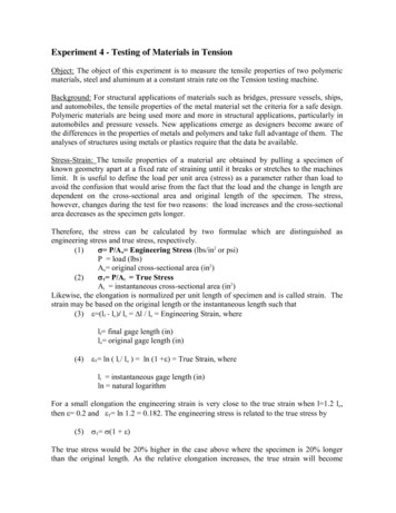
A cylindrical container of radius R 1 m,wall thickness 1 mm is filled with water upto a depth of 2 m and suspended along itsupper rim. The density of water is 1000kg/m3 and acceleration due to gravity is 10m/s2. The self-weight of the cylinder isnegligible. The formula for hoop stress in athin-walled cylinder can be used at allpoints along the height of the cylindricalcontainer.Q.7The axial and circumference stress(σa,σc) experienced by the cylinderwall at mid-depth (1m as shown)area) (10, 10)MPab) (5,10)MPac) (10, 5)MPad) (5, 5)MPa[GATE-2008]Q.8If the Young's modulus andPoisson's ratio of the containermaterial are 100 GPa and 0.3,respectively, the axial strain in thecylinder wall at mid-depth isa) 2 10 5b) 6 10 5c) 7 10 5d) 1.2 10 4[GATE-2008]Q.9A rod of length L having uniformcross-sectional area A is subjectedto a tensile force P as shown in thefigure below. If the Young’s modulusof the material varies linearly fromE1 to E2 along the length of the rod,the normal stress developed at thesection-SS isP(E1 E 2 )A(E1 E 2 )PE1d)PE 2[GATE-2013]PAPE 2c)AE1a)b)Q.10 A circular rod of length ‘L’ and areaof cross-section ‘A’ has a modulus ofelasticity ‘E’ and coefficient ofthermal expansion ‘α’. One end ofthe rod is fixed and other end is free.If the temperature of the rod isincreased by T, thena) stress developed in the rod is E α T and strain developed in therod is α Tb) both stress and strain developedin the rod are zero.c) stress developed in the rod iszero and strain developed in therod is α Td) stress developed in the rod isEαΔT and strain developed inthe rod is zero[GATE-2014 (1)]Q.11 The stress-strain curve for mildsteel is shown in figure given below.Choose the correct option referringto both figure and table.Point on thegraphP.Q.R.S.T.U.Description of the point1. Upper yield point2. Ultimate Tensile strength3. Proportionality limit4. Elastic limit5. Lower yield point6. Failure Copyright Reserved by Gateflix.in No part of this material should be copied or reproduced without permission
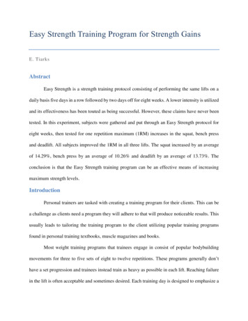
a) P-1, Q-2, R-3, S-4, T-5, U-6b) P-3,Q-1,R-4,S-2,T-6,U-5c) P-3, Q-4, R-1, S-5, T-2, U-6d) P-4, Q-1, R-5, S-2,T-3,U-6[GATE-2014(3)]Q.12 Which one of the following types ofstress- strain relationship bestdescribes the behavior of brittlematerials, such as ceramics andthermosetting plastics, (σ stressand ε strain)?a)b)c)d)developed in the rod isMPa. Young’s modulus of thematerial of the rod is 200 GPa andthe coefficient of thermal expansionis 10 5 per oC.[GATE-2016 (2)]Q.15 A hypothetical engineering stressstrain curve shown in the figure hasthree straight lines PQ, QR, RS withcoordinates P(0,0), Q(0.2,100),R(0.6,140) and S(0.8,130). 'Q' is theyield point, 'R' is the UTS point and'S' is the fracture point.[GATE-2015 (1)]Q.13 A horizontal bar with a constantcross-section is subjected to loadingas shown in the figure. The Young’smodul i for the sections AB and BCare 3E and E, respectively.Q.14The toughness of the material (inMJ/m3) is[GATE-2016 (1)]For the deflection at C to be zero, theratio P/F is[GATE-2016 (1)]Q.16 A square plate of dimension L L issubjected to a uniform pressure loadp 250 MPa on its edges as shownin the figure. Assume plane stressconditions. The Young’s modulus E 200 GPa.A circular metallic rod of length 250mm is placed between two rigidimmovable walls as shown in thefigure. The rod is in perfect contactwith the wall on the left side andthere is a gap of 0.2 mm between therod and the wall on the right side. Ifthe temperature of the rod isincreased by 200 , the axial stressThe deformed shape is a square ofdimension 𝐿𝐿 2𝛿𝛿. If 𝐿𝐿 2 m and 𝛿𝛿 Copyright Reserved by Gateflix.in No part of this material should be copied or reproduced without permission
0.001 m, the Poisson’s ratio of theplate material is[GATE-2016 (3)]Q.17 The state of stress at a point0σ σ σ τ τ τ τ xyzxzzxyzzyandτ τ 50 MPa .xyyxThemaximum normal stress (in MPa) atthat point is[GATE-2017 (2)]Q.18 In the engineering stress-strain curvefor mild steel, the Ultimate TensileStrength (UTS) refers to[GATE-2017 (1)](A) Yield stress(B) Proportional limit(C) Maximum stress(D) Fracture stress.Q.19 An initially stress-free masslesselastic beam of length L and circularcross-section with diameter d (d L) is held fixed between two walls asshown. The beam material hasYoung’s modulus E and coefficient ofthermal expansion α .If the beam is slowly and uniformlyheated, the temperature riserequired to cause the beam tobuckle is proportional to(A) d(B) d2(C) d3(D) d4[GATE-2017 (1)]Q.20 A horizontal bar, fixed at one end (x 0), has a length of 1 m, and crosssectional area of 100mm2. Its elasticmodulus varies along its length asgiven by E ( x ) 100 e x GPa, Wherex is the length coordinate (in m)along the axis of the bar. An axialtensile load of 10 kN is applied atthe free end (x 1). The axialdisplacement of the free end ismm.[GATE-2017 (1)]Q.21 A point mass of 100 kg is droppedonto a massless elastic bar (crosssectional area 100 mm2, length 1m, Young’s modulus 100 GPa)from a height H of 10 mm as shown(Figure is not to scale). If g 10m/s2, the maximum compressionof the elastic bar is mm.[GATE-2017 (1)]Q.22 A steel bar is held by two fixedsupports as shown in the figure andis subjected to an increases oftemperature T 100 C . If thecoefficient of thermal expansion andYoung’s Modulus of Elasticity ofsteel are 11 10 6 / C and 200GPa,respectively, the magnitude ofthermal stress (in MPa) induced inthe bar is .[GATE-2017 (2)]Q.23 The state of stress at a point, for abody in plane stress, is shown in the Copyright Reserved by Gateflix.in No part of this material should be copied o
1.3 Types of stress and strain 2 1.4 Hook’s law and Elastic Property 5 1.5 True Stress and True Strain 5 1.6 Elastic Constants 6 1.7 Types of Materials 7 1.8 Strain Unde