Transcription
STRAY LIGHT ANALYSIS OF THEDIFFUSE INFRARED BACKGROUND EXPERIMENT (DIRBE)Prepared by:Robert P. BreaultBreault Research organization, inc,1161 N. El Dorado place, Suite 340Tucson, AZ 85715For:NASA Goddard space Flight centerunder Contract NAS5-27274March 23, 1984
TABLE OF CONTENTS1 GELIST OF FIGURESiiLIST OF TABLESivINTRODUCTION1CONCEPTS2primary Mirror4Diffraction7SYSTEM MODEL8Higher Levels of Scatter8Sample Points For Diffraction12Aberrations14propagation of Power15BRDF TERMINOLOGY16BIDIRECTIONAL REFLECTANCE DISTRIBUTION FUNCTIONS(BRDF)16WAVELENGTH SCALING 49APPENDIX A:APPENDIX B:ONE REPRESENTATIVE SET OF INPUT DECKSMIRROR BRDF CHARACTERISTICSAPPENDIX C:LISTING OF ALL INPUT DECKS FOR DIRBEANALYSIS (under separate cover)
page iiLIST OF FIGURESFIGURE2PAGELocus of intersections of the main cylindricalbaffle and the conical baffle converging5364951061178The x's mark the sampling points of the 6 pisections used in the APART/FADE analysis.13The x's mark the sampling points of the 3 sections139Example of the variables used in the above1510Pictorial representation of 3 and 80 which are1819111213!APART/FADE models of Martin Black at 10.6 urn . .2122141520Mirror BRDF called the "Best" mirror in the2316Mirror BRDF called the Diamond Turned mirror in2417Mirror BRDF called the "Worst" mirror in the2518Mirror BRDF called the "Worst" mirror in the2619412042
Page iii21Best mirror only PSNIT, 180 degree azimuth.4322Dirty mirror only PSNIT, 180 degree azimuth .4423Diamond turned mirror only PSNIT, 180 degreeazimuth45
Page ivLIST OF TABLESTABLEPAGE1Wavebands12DIRBE specifications straylight PSNIT13Propagation paths for Large off-axis Angles .284PERCENT OF POWER CONTRIBUTED BY EACH OBJECTAS A FUNCTION OF EACH SCATTERING LEVEL29BAND 1 180 DEGREES AZIMUTH PERCENT OF POWERCONTRIBUTED BY EACH OBJECT AS A FUNCTION OFOFF AXIS SOURCE POSITION30OBJECT 98 THE IMAGE CHOP THE POWER DISTRIBUTIONON OBJECT 9831BAND 2 180 DEGREES AZIMUTH PERCENT OF POWERCONTRIBUTED BY EACH OBJECT AS A FUNCTION OFOFF AXIS SOURCE POSITION31BAND 3 180 DEGREES AZIMUTH PERCENT OF POWERCONTRIBUTED BY EACH OBJECT AS A FUNCTION OF OFFAXIS SOURCE POSITION32BAND 4 180 DEGREES AZIMUTH PERCENT OF POWERCONTRIBUTED BY EACH OBJECT AS A FUNCTION OF OFFAXIS SOURCE POSITION32BAND 5 180 DEGREES AZIMUTH PERCENT OF POWERCONTRIBUTED BY EACH OBJECT AS A FUNCTION OF OFFAXIS SOURCE POSITION33BAND 1 ZERO DEGREES AZIMUTH PERCENT OF POWERCONTRIBUTED BY EACH OBJECT AS A FUNCTION OF OFFAXIS SOURCE POSITION34BAND 2 ZERO DEGREES AZIMUTH PERCENT OF POWERCONTRIBUTED BY EACH OBJECT AS A FUNCTION OFOFF AXIS SOURCE POSITION35BAND 3 ZERO DEGREES AZIMUTH PERCENT OF POWERCONTRIBUTED BY EACH OBJECT AS A FUNCTION OFOFF AXIS SOURCE POSITION35BAND 4 ZERO DEGREES AZIMUTH PERCENT OF POWERCONTRIBUTED BY EACH OBJECT AS A FUNCTION OFOFF AXIS SOURCE POSITION36567891011121314
Page v15BAND 5 ZERO DEGREES AZIMUTH PERCENT OF POWERCONTRIBUTED BY EACH OBJECT AS A FUNCTION OFOFF AXIS SOURCE POSITION3616THERMAL INPUT DECK3717Primary Mirror BRDFs3818180 DEGREES AZIMUTH BEST MIRROR PERCENT OFPOWER CONTRIBUTED BY EACH OBJECT AS A FUNCTIONOF OFF AXIS SOURCE POSITION39180 DEGREES AZIMUTH WORST MIRROR PERCENT OFPOWER CONTRIBUTED BY EACH OBJECT AS A FUNCTIONOF OFF AXIS SOURCE POSITION39180 DEGREES AZIMUTH DIRBE DIAMOND TURNED MIRRORPERCENT OF POWER CONTRIBUTED BY EACH OBJECT ASA FUNCTION OF OFF AXIS SOURCE POSITION .40The image plane irradiance due to a hemisphereradiation at 1E-6 watts/sq. mm40192021
1.0INTRODUCTIONThis report discusses the straylight analysis of the Diffuse infraredBackground Experiment (DIRBE) on the Cosmic Background Explorer (COBE)Mission. From the statement of work (SOW), the purpose of DIRBE is tomeasure, or set upper limits on, the spectral and spatial character of thediffuse extra galactic infrared radiation. Diffuse infrared sources withinour own galaxy will be measured. The required reduction of the unwantedradiation imposes severe design and operating restrictions on the DIRBEinstrument. Furthermore, in order to accomplish its mission, it willoperate at a multitude of wavelengths ranging from 1 .25 urn out to 200-300microns. The operating bands are shown in Table 1 and the required pointTable 1.1 .08.037.5120.0Wavebands.-200.0 -1 .515.038.5200 .0300.0Source Normalized irradiance Transmittance (PSNIT) is shown in Table 2 forTable 2.DIRBE specifications straylight PSNIT.Wavelength(in microns)1.510.6100.0PSNIT logPSNIT10-18-15-12.5DETECTOR IRRADIANCE PER UNIT INCIDENT PLANE WAVE.some of the bands. The required PSNIT1s represent performancecharacteristics as good as any telescope yet designed.Section 2 is a brief review of the important straylight concepts in theDIRBE design.Section 3 will explain the model and the assumptions used in the APARTanalysis. It will also cover the limitations due to the scalar theory usedin the analysis.
BROPage 2Section 4 is a detailed description of the BRDP's used.scaling of the BRDF will also be discussed.The wavelengthSection 5 will present the results of the analysis for 5 wavebands,along with the thermal emission and other results.This will be followed by section 6, the conclusions andrecommendations, and section 7 which is a brief summary. Appendix Acontains some APART input files for the DIRBE analysis, and is included withthis report as an example of representative input decks. Appendix B is NASAsupplied mirror BRDF data. Appendix c, supplied under separate cover, is acomputer listing of all the significant input files used in the analysis.in order to accomplish the mission, several constraints were imposed onthe DIRBE instrument. First, an external and large sunshield was designedfor DIRBE and the operating conditions were set so that the Sun and theEarth would always be at 94 degrees or more from the spin axis of theobservatory. This requirement meant that the energy from the sun and Earthfirst had to be diffracted to get to the DIRBE instrument. By design it iseven better than that. It really requires three diffractions because of theplacement of additional vanes on the tip of the Sunshield, which will beshown later.2.0CONCEPTSThe constraints on the position of the Sun and Earth is severe butcertainly allows the system optimum straylight operating conditions. Bethat as it may, there is yet one more very clever straylight technique usedin the DIRBE design. Even the above diffracted energy cannot directly enterthe main baffle of the DIRBE instrument. The diffracted energy can onlyfall on a cone-like forebaffle structure that is highly polished (aluminum).The specular beam is directed out the system, and only the very large backangle scatter off the mirror-like surface can scatter into the vanestructure on the main tube. The large back scatter angle yields aBidirectional Reflectance Distribution Function (BRDF) value far lower thanthe best diffuse black coating. The vane structure then absorbs asignificant amount of this incoming radiation. Therefore, the combinedeffect of the three diffracting edges, the prebaffle, and the black baffles,is the attenuation of the incoming energy from the sun and Earth toacceptable leve1s.It is the secondary sources, the Moon, Jupiter and the generallywidespread diffuse space background that limits the system's performance.The basic design of the system incorporates the "optimum" straylight designfeatures of a well designed system.in the report, considerable attention will seem to be directed towardsa single element type of system, i.e., from the source to the primary andthen directly to the detector. The concept involved is that the incoming
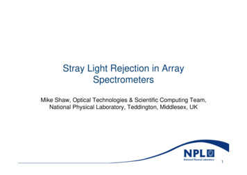
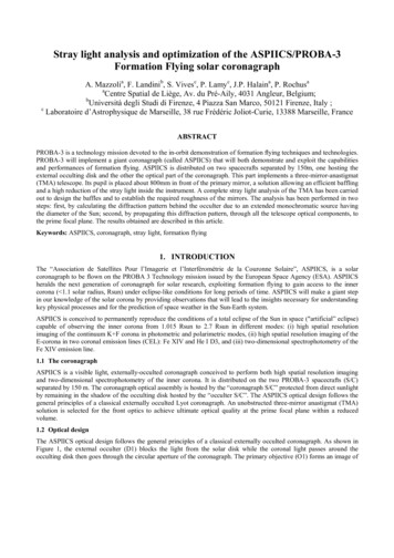
BROPage 3radiation as a function of its off axis position will illuminate certaininternal objects in the system. These objects we will call the "HOT"objects. The detector, on the other hand, will see from its locationanother set of objects that we call "critical" objects. The term criticalbeing used here because they are the sole source of energy to the detectorand are, therefore, critical to the system's performance. Ideally one wouldalways want the two classes of objects to be distinct. But with anunvignetted field of view that is not possible when the source is in thefield of view (FOV) or even when it is just near the FOV because when thesource is just at the edge of the POV, the objective is fully illuminated.Therefore, just outside the FOV most of the primary will still beilluminated. So at least that element is both a HOT object and Criticalobject. Furthermore, in DIRBE, for sources outside the FOV, all the directinput energy will be blocked by the field stop at the prime focus of theobjective. The field stop limits the number of objects in the class of HOTobjects. Nothing beyond the field stop can be illuminated by an out offield source.The use of a field stop doesn't make'a complete straylight system,because as shown in Figure 1, the detector just might, unnecessarily, beable to see through the field stop to some of these Hot objects if itweren't for the Lyot stop in the system. A Lyot stop is an aperture that isconjugate to the system's aperture. Ideally the Lyot stop is at thelocation of the exit aperture and is slightly undersized. Its role is tolimit the number of objects that the detector can see, i.e., it limits thenumber of Critical objects, in the DIRBE design where both a field stop andLyot stop are used, it is possible to have only one object, the objective(the primary in DIRBE) in both classes (Hot and Critical).On axisBundleLyot stop herewould limit raybundleFigure 1.The detector can see throughfield stop.
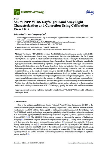
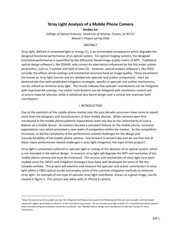
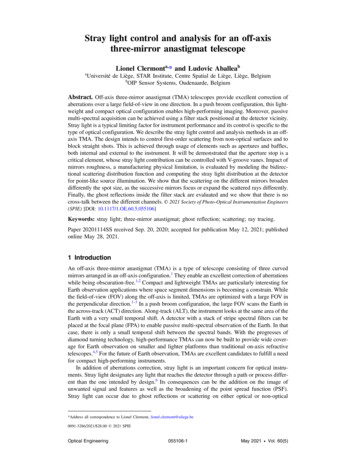
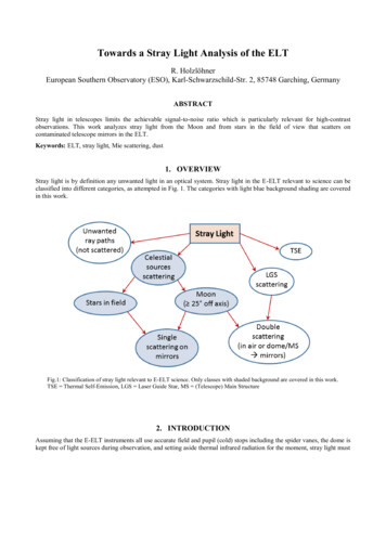
BROPage 4There were two complex details of the model that deserve specialattention. The first was the rectangular cavity between the first Lyot stopand the Tertiary. A special model was developed for this type of cavitywhich was called a "pyramid". in DIRBE, the slopes of the walls arerelatively mild and there was never any peak to the pyramid, therefore,creating a box-like shape. In the final analysis these surfaces had nomeasurable impact on the final results because these occur after the firstfield stop/Lyot stop combination and, therefore, don't receive significantamounts of power.A second detail of the model was both more complex and, also, it had ameaningful impact on the analysis. The main baffle around and in front ofthe primary mirror had two major parts, one, a cylindrical tube from theentrance aperture to the primary, and second, a conical tube from theprimary to the first Field stop (FS1). These two surfaces intersected eachother forming a complex junction of vane surfaces.The new version of APART was able to model these objects as a series offive objects (10, 11,34, 17 and 38), see Figure 2. object 10 was the shortfront, fully cylindrical, section, objects 11 and 34 were also cylindricalsections but they have their lower sections sliced away to make room forobject 17 and 38, (each of which had their corresponding upper sectionsremoved). The reason that there are two cylindrical sections (11 and 34)and two conical sections (17 and 38) is that the profile of the intersectionof the objects was not a straight line as shown in Figure 3. APART only hasslicing planes. Hence, two objects were modeled with different slicingplanes.2.1Primary MirrorLet us discuss the primary mirror to see what affects the magnitude ofits BRDF. In the long run it will warrant every bit of attention given toit. if the surface is to be coated, i.e., with an aluminum thin filmcoating, then the surface contamination at the time of the application ofthe thin film is extremely important, and save for recoating of the surface,its effect is irreversible, improper coatings can cause a BRDF tounnecessarily increase by a factor of 50 if only modest attention is paid tothe cleaning process.Characteristically metal mirrors have not performed as well as theirglass counterparts when rated according to their BRDF's. Sleeks seem toabound on metal mirrors to a noticeably higher degree than on glass. Themeasured BRDF supplied by NASA, Appendix B, seems to contradict this, butthey are not necessarily representative of the general cases.In the DIRBE instrument the straylight that reaches the detector willeither be from the primary mirror or from diffraction off the apertures. Ifthe primary is the major source of unwanted energy, then there are two waysto make improvements. The first is to do what is necessary to improve(lower) the scattering characteristics (BRDF) of the primary's surface. This
BROPage 5Slicing planesActual location of Intersection20u.t, ra2wM J t,EfeM 05P e.ot. E-iO COzac JM Ww -20U tna(/I EHa coaKEH M2 CMM I *-40' : Ka E-« SMU. KO O.I!S EHy w-80 --100 HoKLMBAFFLE VANE AXIAL LOCATIONSFigure 2.Locus of intersections of the maincylindrical baffle and the conicalbaffle converging from the primary
Page 6BROBreault ResearchOrganization, Inc.V —2Figure 3.F- R O F- X l EProfile Y-Z plane DIRBE.
BROPage 7involves the substrate, the degree of polish, cleaning, coating and keepingany pre-launch contamination from getting to the primary.The second way to improve the system is to keep unwanted energy fromreaching the primary. As explained above, this has already been achievedfor sources at large off-axis angles. For intermediate off-axis angles theonly path to the primary is via multiple scatter from the vaned main baffle.The appropriate constraint on the vane spacing is that over the range ofangles of the source there be no direct path from the source to the maintubes wall that can then scatter directly to the primary, if this conditionis met, then the incoming radiation should be attenuated by five or moreorders of magnitude by the vanes, if not, it may be as little as only oneorder of attentuation. in the DIRBE design the baffles, if anything, aretoo close together. This over design will have only a minor detrimentaleffect which comes mainly from the additional edge scatter.For small off axis angles, those that can put power directly onto theprimary mirror, the only method to improve performance is to reduce thescatter off the primary. This requires both making a low scatter mirror,and then KEEPING it clean. Both will require a significant amount ofeffort.2.2DiffractionThe second source of unwanted energy is from multiple diffractionpaths. One method most commonly used to beat down the diffracted energy isto baffle the diffraction from the edges. This is done in concept in DIRBEthrough the use of multiple Field stops (FS), an Aperture stop, and a LyotStop, in order for these multiple stops to be effective, the diffractionmust be sufficiently blocked by a succeeding aperture at a conjugate imagelocation. DIRBE's apertures are all there in concept, but theirmathematical precision precludes optimum performance. That is, they are soclosely lined up that even with first order theory there is not much of abreak in the angle that the incoming ray diffracts to the next aperture.Hence, there is not as much attenuation, especially at the long wavelengths.This will be discussed in detail in Section 3.in summary for this section, the DIRBE system has a tight constraint onits operating conditions, it is well designed for scattered light and hasthe making of an excellent system to suppress diffracted energy but isn'tquite there yet. Based upon assumed mirror BRDFs, the performance will belimited by mirror scatter from the primary. Hence, the post launchscattering characteristics of the primary will be crucial.
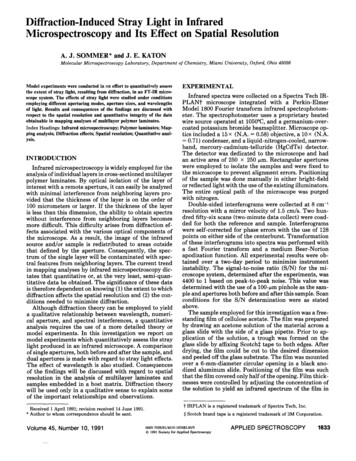
BRO3.0Page 8SYSTEM MODELThe DIRBE system is far more complex than is practical to fully modelinto APART. Most of the fine detail of nuts, bolts and rivets create noadverse impact on the final results when left out of the analysis. Everyeffort has been made to model the DIRBE system in sufficiently accuratedetail in order to preclude erroneous results. The analysis was, in fact,delayed significantly because some APART program development was requiredbefore this analysis could be performed.However, the system is modeled in detail from the Sunshield to thechopper blade. Many of the objects modeled into the analysis serve only anaesthetic purpose, having no impact on the system's performance. A profileof the system is shown in Figures 2, 4, 5 and 6 (at different profiles andscales). Note that the details of the vanes do not directly show up in theFigures. This is a characteristic of APART which considers the vanes as acomplex absorbing coating.The numbers shown in Figures 2, 4, 5, and 6 represent surfaces modeledinto the program and the number by which this surface was designated in theanalysis, in order to aid the reader, a literal assignment was also givento each object. The input file for program 1 of APART is shown in Table 1Ain Appendix A. This table calls out the object shape, number, and itsassigned literal, along with additional program details.3.1Higher Levels Of ScatterThe program was modified to handle higher levels of propagation paths,i.e., it could trace more "bounces" of scatter, and/or more diffractions ina single path. The program arrays were increased in size in order to dealwith nine (9) levels of scatter. For practical reasons, the program was notincreased to the eleven levels of scatter or diffraction that are necessaryfor the very large off axis angles. The results for the larger off-axisangles, those that would require the 11 levels of scatter, have the finaldiffraction path going from the first field stop directly to the chopper.This will give results approximately three or four orders of magnitude abovethe expected diffraction results for the first three bands. There areseveral reasons that the higher level results were not pursued. In thelower three bands the diffraction is a relatively small contributor ofpower. The diffraction results, as calculated from FS1 directly to thechopper blades, push the computer limits on its exponential representationof numbers. The higher levels of diffraction would be treated as zeros. Atthe two longer wavebands (160um and 250um) the second field stop is sonearly aligned with the image of the first field stop (FS1) relative to thewavelength, that the PADE program automatically shifts from one type ofdiffraction analysis (STATIONARY Phase) to another (CONSTANT Phase) wherethere is very little attenuation due to the succeeding diffraction, inother words, the second field stop is ineffective.
Page 9BROBreauh ResearchOrganization, Inc.X —ZF-ROFILEXFigure 4.Profile X-Z plane DIRBE.
Page 10BRO4-5 {r 70DIRJ3EFigure 5.V—ZRRORILEProfile Y-Z including sunshield.
page 11BRO3.I2'4X —ZFigure 6.RRORILEProfile X-Z including sunshield.
BROPage 12The output will show the results of these complications in greaterdetail, in summary then, the predicted system performance will be accuratebecause mirror scatter dominates in the lower three bands and thediffraction from FS1 will closely approximate the system performance in theupper two bands where scatter is not as significant.3.2Sample points For DiffractionThe shift from the more typical stationary phase contribution in thelower three bands to a constant phase contribution in the upper two bandsrequired a more in depth analysis.The APART/PADE program has two first order imaging routines that can beselected to calculate conjugate image locations. Both were used in theDIRBE analysis in order to try to determine the sensitivity of thediffraction from FS2 to the incoming diffracted energy from FS1.Nevertheless, both routines gave essentially the same results, indicatingthat the edges are optically very closely aligned.An in depth analytical review revealed that the program was accuratelycalculating the performance based upon the finite set of points selected oneach source and collector. Because of this mathematical sampling, there wasa problem in the analysis that could be clearly explained but one that couldnot be restructured at this time. There is a set of conditions that arerequired for this problem to occur, and, unfortunately, all of them aresatisfied for this portion of the analysis in DIRBE.First, all the important source points, collector points, anddiffraction peaks are in the meridional plane. Second, the diffractionpeaks fall almost precisely on the sampled collector points. In the DIRBEanalysis the source point is always in the meridional plane; only the 0degree and 180 degree azimuths were analyzed, second, all circular orelliptical diffracting edges had 6 sampling points. Hence, there always wasa sample point in the 12 o'clock position and another one in the 6 o'clockposition, see Figure 7. For the rectangular (square) apertures, the edgeswere made up of four straight edges with three sample points on each edge.For the top and bottom edges the center point was in the meridional plane,see Figure 8. By design FS1 is conjugate with FS2, thus satisfying the lastcondition.Before jumping to any simple solutions, it is wrong to think that thesolution is to move the sample points out of the meridional plane, whichcould easily have been done. Analytically the propagated energy would dropdramatically. Not only to a level well below those of this analysis, butalso below the actual system performance. The reason is that for points in
BROPage 13Figure 7.The X's mark the sampling points of the6 pi sections used in the APART/FADE analysis.Figure 8.The X's mark the sampling points of the3 sections of each diffracting edge.
BROPage 14the meridional plane, i.e., the ones used in thisnearly perfect alignment with a real peak (SPIKE)collector point as used in this analysis. That'scollector point to some other location could giveirradiance on the edge.analysis, there is thisin the diffraction at theall real and moving the.an apparently lowerThe real analytical problem is that the calculated values DO NOTrepresent the average values over the collector areas involved, i.e., thelength of the following diffracting edges or the area on the chopper blade.The values accurately representing local peaks are "spread" over too large asource or collector areas, thereby calculating erroneously high propagatedpowers. Only super fine sampling could give sufficient resolution toresolve this kind of problem. in the analysis this was not necessary because either the scatter fromthe primary mirror was the dominate source, or the diffraction from FS1because of its alignment with FS2 dominated. When the diffraction from FS1dominates, one of the major conditions above is not met. The FS1 and thechopper area are not conjugate. Therefore, the diffraction pattern is arelatively slow varying function, which means that the sampled points dorepresent the sampled area.3.2.1Aberrations -There is one other limitation in the diffraction analysis. PADE standsfor paraxial Analysis of Diffracted Energy. There are optical aberrationsin the real DIRBE system. The diffraction spikes discussed above were basedon a first order, diffraction limited, type of system, in DIRBE the imageof FS1 , at FS2, is significantly aberrated. Because of these aberrations,some rays will get through FS2 and will then propagate to the edge of anyimage location, i.e., anything conjugate to the field stops. This willcause a local high around the edge of the image of the field stop. The sameaberrated rays will be fairly uniformly spread over the Lyot stop, or anyplane conjugate to it such as the chopper blade. The actual magnitude ofthis level of energy is dependent upon the optical design and its alignment.The solution is an optical design problem.The quality of the image at the field stops can only be improved byusing some of the parameters of the optical surfaces to improve the imagequality, or by reducing the clear aperture size of the succeeding conjugateapertures in order to clip off all the aberrated rays. The latter is donein DIRBE to some extent.When analyzing a system which is so closely aligned, the aberrations canalso effect the calculated magnitude of the diffraction at the apertures.The actual irradiance could be higher or lower than the calculated valuesdepending on the aberration, its sign, and its magnitude. The aberrationscould move the centroid either closer to the edge or further away, in theanalysis these aberrations play a role in the performance of the edges of
BROPage 15FS1 to FS2. Recall that the performance is limited by the primary and FS1,as presently designed. The near perfect alignment of FS1 and FS2 causesalmost no change in the diffraction performance due to the second fieldstop.3.2.2Propagation of Power The basic equation used in APART to trace the propagation of power is:d f c L dAs cos8s dAc d8c/R2The equation relating power transfer from one section to another iswhere d(f c is the differential power transferred. L is the bidirectionalradiance of the source section. dAs and dAare the elemental areas ofthe source and collector. 6 and 9", are the angles that the line of sightfrom the source to the collector makes with their respective normals. Thisequation can be rewritten as three factors that help simplify the reductionof scattered radiation.cos6ccos 6 1sR2 j c BRDF j sGCFwhere GCF stands for the Geometrical Configuration Factor, which is also theprojected solid angle that the collector subtends from the source. Anexample is shown in Figure 9.Figure 9.Example of the variables used inthe above equation.
BRO4.0Page 16BRDF TERMINOLOGYNo measured data for the DIRBE optics exists. Therefore, thescattering characteristics of the mirrors had to be assumed. Thesecharacteristics are best presented in the form of a BidirectionalReflectance Distribution Function (BRDF). In fact, the whole next sectionis dedicated to BRDFs. At first glance, it would seem that all bases arecovered by the parametric analysis of the BRDF of the primary included inthis report in the results section. Four different BRDFs were used torepresent the different BRDFs that might be achieved for DIRBE1s primarymirror; from excellent to less than average. That is all well and good forthe first two, maybe three bands. What happens to the BRDFs out at 160 to250 urn is unknown. There is no BRDF data for mirror surfaces beyond 38 urn.APART used a wavelength scaling law, that has a sound analytical basis, toscale the BRDFs from 10 urn to 250 um, but there is no empirical data tocorroborate such scaling.Based upon the latest technology, it now seems possible to make suchmeasurements. In the past, data has been presented that was thought torepresent mirror BRDFs at long wavelengths. It is now understood that suchdata really represented the instrument profile, and not the BRDF of themirror. The BRDF measurement of a mirror at the long wavelengths will bedifficult because of the wavelength, the required detectors, and the verylow BRDFs if the scaling law is accurate. There is some empirical supportnow that would indicate that nothing drastically changes the mirror BRDF'sat the long wavelengths, as it does for black surfaces. The infraredAstronomical satellite (IRAS) had an operating range not too unlike DIRBE's.It did not show any startling changes in performance that could beattributed to the BRDFs of the mirrors.4.1BIDIRECTIONAL REFLECTANCE DISTRIBUTION FUNCTIONS(BRDF)The absorbing and scattering characteristics of the surfaces in anysystem play a significant role in its ultimate stray light performance. Theoptical, baffle, and vane design play a more significant role because,unlike BRDFs, they can completely block a propagation path, i.e., make it goto zero, which is something no BRDF can achieve. DIRBE, by design, does allit can to block stray light paths. Those that are left are affected by theBRDFs of their surfaces.In DIRBE we only have the following three (3) coatings to discuss:1)Mirror BRDFs of the optical surfaces.
BROPage 172) Blacks.3) Mirror like finish of the forebaffle.Diffraction is another type of "coating" that can be assigned to anedge since FADE allows the user to choose between Sommerfeld or Kirchhofftype diffraction.in the DIRBE analysis, assumed BRDFs were used for the three moreconventional coatings cited above.The data are presented in a form called B0 plot, after theHarvey-Shack theory. As shown in Figure 10, So is the sine of the angle ofspecular reflection (even for a diffuse surface) and 3 is the sine of theobservation angle. The data are then plotted on a log-log plot of the BRDFversus 3-3Q.This type of plot is especially significant for micro roughsurfaces, i.e. mirrors.By design, there are so many light traps for sources beyond the planeof the sunshield that any reasonable variation in the BRDF of the forebafflewill probably not be significant. Its assumed BRDF is shown in Figure 11.For the remaining paths of stray light, the BRDF of the black coatingof the baffles on the main tube and the BRDF of the primary mirror areimportant and could result in DIRBE not meeting the required specs. Thevanes were assumed to have Martin Black coating. Specific profiles of theAPART BRDF models of Martin Black used for the analysis and some measureddata are shown in Figures 12 and 13.For the longer wavebands Martin Black turns specular, and as such ispotentially a major problem. The program has a special specular vane cavityroutine, developed for IRAS, that was used in this DIRBE analysis. Thisroutine indicated that there were 24 specular paths from objects 6 to 11,then the primary and another 9 paths from 9 to 11 , then to the primary.Fortunately, these affect only the higher off axis sources for which thereis a sufficient margin of error.The assumed BRDFs for the mirror in the 10.6 ym band are plotted inFigures 14 through 17 and are shown in Table 17. The data represents arange of BRDF's, any of which could be representative of a DIRBE primary.The BRDF's in the other bands were usually scaled from these values. Theexceptions are shown in Figures 17 and 18 which are bas
STRAY LIGHT ANALYSIS OF THE DIFFUSE INFRARED BACKGROUND EXPERIMENT (DIRBE) Prepared by: Robert P. Breault Breault Research organization, inc, 1161 N. El Dorado place, Suite 340 Tucson, AZ 85715 For: NASA Goddard spa