Transcription
Cbus TCP Driver User GuideCbusTCP DriverUser Guide
Table of ContentsInstallation . 1Requirement. 2MIG-112 Configuration . 4Default IP address . 4Change IP address . 6Quick Start . 8Configure Cbus Tcp Network . 8Add a CbusTcpNetwork . 9Add a Cbus Devices . 10Create Cbus Proxy Point . 11FG Cbus View.14Cbus Device Manager . 14Cbus Point Manager . 17Cbus Event Logs . 21Cbus Alarms . 22Cbus Proxy Ext Special Consideration . 25Licensing .26
C B U ST C PD R I V E RU S E RG U I D EChapter1InstallationInstall ifcCbusTcp.jar on the computer where Niagara AX Workbench will run. To install, place a copy ofthe file in the modules directory of your Niagara AX installation. This is typically C:\Niagara\Niagara3.n.nnn\modules.Install ifcCbusTcp.jar module on the target station. Using a Niagara AX workbench where the modulehas already been installed, connect to the stations platform service. Go to the software manager andinstall ifcCbusTcp.Apart from installing the 4.n.nn version of the Niagara distribution files in the JACE, make sure to installthe ifcCbusTcp module too (if not already present, or upgrade if an older revision). For more details, see“About the Commissioning Wizard” in the JACE Niagara AX Install and Startup Guide.Following this, the station is now ready for Cbus software integration, as described in the rest of thisdocument.1
C B U ST C PD R I V E RU S E RG U I D ERequirement AX workbench 3.x.xx or higher.1. TCP Port connection. AX platform support:1.2.3.4.5.2Web Supervisor.JACE 3E.JACE 6xx.JACE 7xx.JACE 8000 (Titan Jace). Compatibility with controllers of Excel 5000 family (XL50, XL80, XL100, XL500, XL600 and ZoneManager). Support baud rate 9600, 19200 and 38400. Support parallel connection to the existing Cbus network (XBS, EBI, SymmetrE). Flexible sizing up to max. 30 C-Bus devices per Driver network. Reading and writing from DDC points of type Digital Input, Digital Output, Analog Input, AnalogOutput, Pseudo Digital, Pseudo Analog and totalizer. Support devices alarm such a point overridden, fault alarm, high/low alarm and system alarms.
C B U ST C PD R I V E RU S E RG U I D EOptions 1Note: Make sure the Cbus RS485 connection is connected at the terminal D2 /D2-:Below is the default setting:1. Cbus baud rate by default is 9600 kbps, make sure it is matching with all the controllerin the network,2. Cbus bus Id by default is 29 make sure this address is not being use by any Cbuscontroller in the network.3
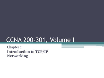
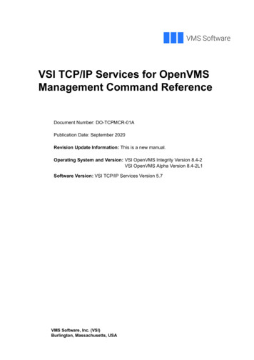
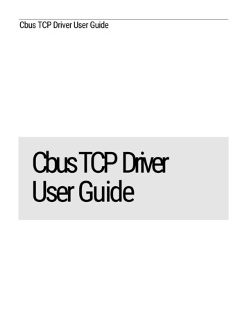
C B U ST C PD R I V E RU S E RG U I D EChapter2MIG-112 ConfigurationThis section provides a collection of procedures to configure the MIG-112/FG-20 setting.Default IP address By the default from the factory the IP address is “192.168.10.11”. User may require to change the default IP address to suite the network requirement. To take effectthe changes MIG-112 controller required to reboot. Run the web browser from the computer and key in the MIG-112 controller IP address with login theuser name and password as below:Address : http://192.168.10.11 or https://192.168.10.11 (SSL).User: userPassword : pass4
C B U S5T C PD R I V E RU S E RG U I D E
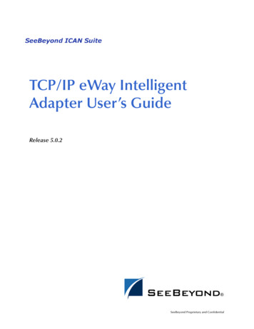
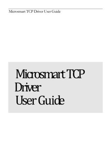
C B U ST C PD R I V E RU S E RG U I D EChange IP address After login to the MIG-112 web browser go to the “LAN” from the tree navigation, change the desireIP address and press the button “Submit”. Finally reboot the MIG-112 to take effect. Below is to change the Cbus configuration, baud rate by default is 9600 and bus id by default is 29,make sure the bus id is not used by other Cbus controller in the network. Improper setting maycause the communication unstable.6
C B U S7T C PD R I V E RU S E RG U I D E
C B U ST C PD R I V E RU S E RG U I D EChapter3Quick StartThis section provides a collection of procedures to use the AX Cbus Tcp drivers to build networks ofdevices with proxy points and other components. Like other AX drivers, you can do most configurationsfrom special “manager” views and property sheets using Workbench. For any of the Cbus TCP networks: “Configure the Cbus Tcp network”“Add Cbus devices”“Create Cbus proxy points”Configure Cbus Tcp NetworkTo add and configure a Cbus Tcp network, perform the following main tasks: Add the Cbus TCP network, as needed: 8Add a CbusTcpNetwork
C B U ST C PD R I V E RU S E RG U I D EAdd a CbusTcpNetworkTo add a CbusTcpNetwork in the stationUse the following procedure to add a CbusTcpNetwork component under the station’s Drivers container.Note : If the host JACE has plan to connect to multiple MIG112 Cbus Gateway to be used for client(master) access of Cbus networks, add one CbusTcpNetwork for each MIG112 Cbus Gateway. Note thatfor each CbusTcpNetwork, you must Configure the Ip Address and TCP port parameters.( by default theport is 10101).Note : Only single connection can be made at once into the MIG112 controller TCP port connection,multiple connection from the multiple software or computer will not allowed.To add a CbusTcpNetwork in the station: Double-click the station’s Drivers container, to bring up the Driver Manager.Click the New button to bring up the New network dialog. For more details, see “DriverManager New and Edit” in the Drivers Guide.Select “Cbus Tcp Network,” number to add: 1 (or more if multiple networks) and click OK. Thisbrings up a dialog to name the network(s).Click OK to add the CbusTcpNetwork(s) to the station. You should have a CbusTcpNetworknamed “CbusTcpNetwork” (or whatever you named it),under your Drivers folder, initially showinga status of “{ok}” and enabled as “true.”Configure the Ip Address and TCP port parametersIn the CbusTcpNetwork property sheet for each network, you must set the Ip Address and Tcpport configuration to match communications parameters.To set the Ip Address and Tcp port parametersTo set the Ip Address and Tcp port parameters for a CbusTcpNetwork: Right-click the CbusTcpNetwork and select Views Property Sheet.The Property Sheet appears. 9Scroll down
C B U ST C PD R I V E RU S E RG U I D ESet the properties for the MIG112 Cbus Gateway connection, where defaults are: Ip Address: 192.168.10.11 — Enter the MIG112 Cbus Gateway ip address TCP Port: 10101 – Bind to RS485 D1 /D1-. TCP Port: 10102 – Bind to RS485 D2 /D1-. Click the Save button.Add a Cbus DevicesAfter adding a Cbus Tcp network, you can use the network’s default “device manager” view to add theappropriate Cbus devices. You also could use discover the device automatically by pressing the button“discover”.Note: You need the address information for each Cbus device you are adding, as well as for laterprocedures to add proxy points under devices.To add a Cbus device in the networkUse the following procedure to add the correct type of Cbus device in the network. To add a Cbusdevice:10
C B U S T C PD R I V E RU S E RG U I D EIn the Nav tree or in the Driver Manager view, double-click the client network, to bring up thedevice manager (Cbus Device Manager). All of these device manager views operate in a similarfashion.Note: For general device manager information, see the “About the Device Manager” section in the DriversGuide. Click the New button to bring up the New device dialog. Select for number to add: 1 (or more, if multiple) and click OK.This brings up a dialog to name the device(s), enter Cbus device. Any Cbus Device needs the unique address in use.Click OK to add the Cbus device(s) to the network.You should see the device(s) listed in the Cbus Device Manager view, showing a status of “{ok}”and enabled as “true.”If a device shows “down” check the configuration of the network and/or Cbus device address.You can simply double-click a device in the device manager to review settings in an Edit dialog,identical to the New dialog when you added it.After making any address changes, click Save, then right-click the device and select Actions Ping.Create Cbus Proxy PointAs with device objects in other drivers, each Cbus device has a Points extension that serves as thecontainer for proxy points. The default view for any Points extension is the Point Manager (and in thiscase, the “Cbus Point Manager”). You use it to add Cbus proxy points under any Cbus device.Note: Unlike the point managers in many other drivers, the Cbus Point Manager does offer a “Learnmode” with a Discover button and pane. Otherwise you can simply use the New button to createproxy points, referring to the vendor’s documentation for the addresses of data items in each Cbusdevice.To add Cbus proxy pointsOnce a Cbus device is added, you can add proxy points to read and write data. If programming online(and the device shows a status of “{ok}”), you can get statuses and values back immediately, to helpdetermine if point configuration is correct. Use the following procedure:11
C B U ST C PD R I V E RU S E RG U I D ETo create Cbus proxy points in a device: In the Device Manager, in the Exts column, double-click the Points iconrepresenting the device you wish to create proxy points.in the rowThis brings up the Cbus Point Manager. (Optional) Click the New Folder button to create a new points folder to help organize points, andgive it a short name, such as “TempNo1”, or whatever name works for your application. You canrepeat this to make multiple points folders, or simply skip this step to make all proxy points inthe root of Points. Note that all points’ folders have their own Cbus Point Manager view, just likePoints. If making points folders, double-click one to move to its location (and see the pointmanager). At the location needed (Points root, or a points folder), click the New button. The New pointsdialog appears, in which you select a “Point Type,” “Number to Add,” “Point Id and Element”.For more details, see “About Cbus proxy points” Click OK to add the proxy point(s) to the Points extension (or to the current points folder), whereeach shows as a row in the point manager.If parameter correctly, each point should have a status of “{ok}” with a polled value displayed.12
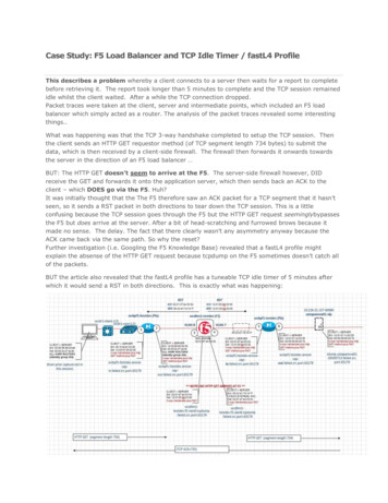
C B U S 13T C PD R I V E RU S E RG U I D EIf a point shows a “{fault}” status, check its ProxyExt “Fault Cause” property value, whichtypically includes a Cbus “exception code” string, such as “Read fault” In such a case, recheck the address in the point against the documented address for the data item.Continue to add proxy points as needed under the Points extension of each Cbus device. Asneeded, double-click one or more existing points for the Edit dialog, similar to the New dialogused to create the points. This is commonly done for re-editing items like data addresses,names, or facets.
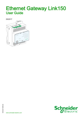
C B U ST C PD R I V E RU S E RG U I D EChapter4FG Cbus View Cbus Device ManagerCbus Point ManagerCbus Device ManagerThe Cbus Device Manager is the default view when you double-click on a Cbus Tcp Network in the Navtree. This manager view provides a quick and easy way to display.The Cbus Device Manager is the default view for any Cbus Tcp Network container. The Cbus DeviceManager is a table-based view, where each row represents a unique device. When building a network inthe station, you use this view to create, edit, and delete device-level components. Below is an exampleCbus Device Manager view.14
C B U ST C PD R I V E RU S E RG U I D EThe view above shows a typical Cbus Device Manager view.The “New Folder”, “New”, and “Edit” buttons are not unique to the Cbus Device Manager, and areexplained in the “AX User’s Guide” in the “Driver Architecture” section. The “Match” button is not usedfor the Cbus driver.You can now add the devices to the station database by clicking the “Add” button. This will pop up the“Add” dialog box:15
C B U ST C PD R I V E RU S E RG U I D EThe “Add” dialog box affords you the opportunity to tweak the display name, enabled state, and/oraddress of each of the selected devices. Click the “OK” button to add the devices to the database, orclick “Cancel” to bail out.The “Discover” button implements functionality that is unique and tailored to discovering Cbus devices.By clicking the “Discover” button, the “learn” mode of the manager is invoked (the panes will be split,and a “discovery” table will be displayed in the top pane) .16
C B U ST C PD R I V E RU S E RG U I D ESingle or multiple Cbus devices can be added as device by selecting the discovered row(s) in the toppane, and clicking add. Doing so will cause the “Add” dialog box to appear: Once the device(s) aresatisfactorily edited, click “OK” to create the device corresponding to the device property.Cbus Point ManagerThe Cbus Point Manager is the default view when you double-click on a “points” folder (aCbusPointDeviceExt type folder) under a CbusDevice in the Nav tree. This manager view provides aquick and easy way to display and learn Cbus points in a Cbus device.The Cbus Point Manager is the default view for any CbusPointDeviceExt container. The Cbus PointManager is a table-based view, where each row represents a unique Cbus address within a device.Below is an example Cbus Point Manager view.17
C B U ST C PD R I V E RU S E RG U I D EThe “New Folder”, “New”, and “Edit” buttons are not unique to the Cbus Device Manager, and areexplained in the “AX User’s Guide” in the “Driver Architecture” section. The “Match” button is not usedfor the Cbus driver.The “Discover” button implements functionality that is unique and tailored to discovering Cbus devicespoints. By clicking the “Discover” button, the “learn” mode of the manager is invoked (the panes will besplit, and a “discovery” table will be displayed in the top pane) .18
C B U ST C PD R I V E RU S E RG U I D ESingle or multiple points can be added as control points with CbusProxyExt extensions by selecting thediscovered row(s) in the top pane, and clicking add. Doing so will cause the “Add” dialog box to appear:Once the point(s) are satisfactorily edited, click “OK” to create the proxy points corresponding to thepoint property.19
C B U S20T C PD R I V E RU S E RG U I D E
C B U ST C PD R I V E RU S E RG U I D ECbus Event LogsAny Cbus event log such a point override, high/low alarms from the device wills log to the event loghistory, The event log can be define from the specified Cbus Device property.The Cbus event log can be view from the AX Alarm Console Recipient.21
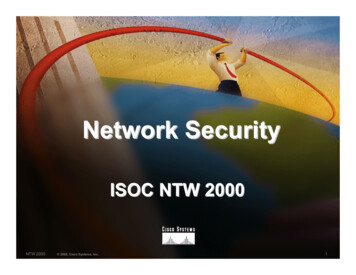
C B U ST C PD R I V E RU S E RG U I D ECbus AlarmsAny Cbus alarm such a point override, high/low alarms from the device wills route to the alarm console,the alarm can be define from the specified Cbus TCP Network property and at the individual Cbus proxyextension point.By enabling the Cbus alarm at the Cbus TCP Network “Accept Alarm” property system will receive thealarm and route automatically to the standard alarm console.22
C B U ST C PD R I V E RU S E RG U I D EThe alarm point can define at the Cbus Proxy Extension, simply select the “Alarm Class” property andselect from the existing alarm class list and the alarm will automatically route to the selected alarmclass.23
C B U S24T C PD R I V E RU S E RG U I D E
C B U ST C PD R I V E RU S E RG U I D ECbus Proxy Ext Special ConsiderationWhenever a Cbus proxy Ext is added or configured to have an point property value and the base Type isWritable Point as shown below, there is additional special behavior need to take note:Some of the command point required to use override(priority 1-10) to change the value, as when the“set” action is execute the output will not change unless user use override(priority 1-10) to change thevalue.25
C B U ST C PD R I V E RU S E RG U I D EChapter5LicensingCbus driver License is running independently from the Tridium license, it has no restriction to run to any of theexisting license vendor.The Cbus license provide 2 hour demo license without the unlock code. After the demo license expired theCbus Driver communication will stop automatically and will show fatal fault at the Cbus TCP Network level.“ifcCbusTcp license expired”. To extend the demo period user required to restart the station.26
C B U ST C PD R I V E RU S E RG U I D ETo request the license submit the JACE/Web Supervisor host ID, to unlock the driver simply go to the licenseproperty action and invoke command “License Update”, the dialog “License Update” will appear. Place thesignature code at the “Signature” property. Please take note the license only provide by authorize vendor. Ifthe signature code is successful enter the property “Mode” will automatically change to “registered” and useris required to restart the station to take effected.***end***27
Configure the Ip Address and TCP port parameters In the CbusTcpNetwork property sheet for each network, you must set the Ip Address and Tcp port configuration to match communications parameters. To set the Ip Address and Tcp port parameters To set the Ip Address and