Transcription
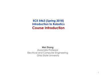
RoboticsKinematicsKinematic map, Jacobian, inverse kinematicsas optimization problem, motion profiles,trajectory interpolation, multiple simultaneoustasks, special task variables,configuration/operational/null space,singularitiesMarc ToussaintUniversity of StuttgartWinter 2014/15
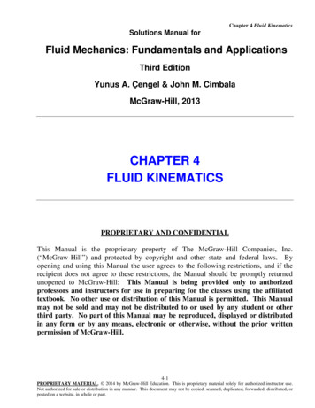
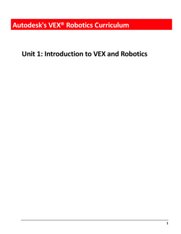
Two “types of robotics”:1) Mobile robotics – is all about localization & mapping2) Manipulation – is all about interacting with the world0) Kinematic/Dynamic Motion Control: same as 2) without ever makingit to interaction. Typical manipulation robots (and animals) are kinematic treesTheir pose/state is described by all joint angles2/62
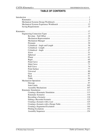
Basic motion generation problem Move all joints in a coordinated way so that the endeffector makes adesired movement01-kinematics:./x.exe -mode 2/3/43/62
Outline Basic 3D geometry and notation Kinematics: φ : q 7 y Inverse Kinematics: y 7 q argminq φ(q) y 2C q q0 2W Basic motion heuristics: Motion profiles Additional things to know– Many simultaneous task variables– Singularities, null space,4/62
Basic 3D geometry & notation5/62
Pose (position & orientation) A pose is described by a translation p R3 and a rotation R SO(3)– R is an orthonormal matrix (orthogonal vectors stay orthogonal, unitvectors stay unit)– R-1 R – columns and rows are orthogonal unit vectors– det(R) 1 RR12 11– R R21R22 R31 R32R13 R23 R33 6/62
Frame and coordinate transforms Let (o, e1:3 ) be the world frame, (o0 , e01:3 ) be the body’s frame.The new basis vectors are the columns in R, that is,e01 R11 e1 R21 e2 R31 e3 , etc, x coordinates in world frame (o, e1:3 )x0 coordinates in body frame (o0 , e01:3 )p coordinates of o0 in world frame (o, e1:3 )x p Rx07/62
Rotations Rotations can alternatively be represented as– Euler angles – NEVER DO THIS!– Rotation vector– Quaternion – default in code See the “geometry notes” for formulas to convert, concatenate & applyto vectors8/62
Homogeneous transformations xA coordinates of a point in frame AxB coordinates of a point in frame B Translation and rotation: xA t RxB Homogeneous transform T R4 4 : R TA B 0 t 1 R xA TA B xB 0BB t t Rx x 111 in homogeneous coordinates, we append a 1 to all coordinate vectors9/62
Is TA B forward or backward? TA B describes the translation and rotation of frame B relative to AThat is, it describes the forward FRAME transformation (from A to B) TA B describes the coordinate transformation from xB to xAThat is, it describes the backward COORDINATE transformation Confused? Vectors (and frames) transform covariant, coordinatescontra-variant. See “geometry notes” or Wikipedia for more details, ifyou like.10/62
Composition of transformsTW C TW A TA B TB CxW TW A TA B TB C xC11/62
Kinematics12/62
iveeff.offsetW A kinematic structure is a graph (usually tree or chain)of rigid links and jointsTW eff (q) TW A TA A0 (q) TA0 B TB B 0 (q) TB 0 C TC C 0 (q) TC 0 eff13/62
Joint types Joint transformations: TA A0 (q)depends on q Rnrevolute joint: joint angle q R determines rotation about x-axis: 10TA A0 (q) 00 000 cos(q) sin(q) 0 sin(q) cos(q) 0 001prismatic joint: offset q R determines translation along x-axis: 10TA A0 (q) 00 01000010 q 0 0 1others: screw (1dof), cylindrical (2dof), spherical (3dof), universal(2dof)14/62
15/62
Kinematic Map For any joint angle vector q Rn we can compute TW eff (q)by forward chaining of transformationsTW eff (q) gives us the pose of the endeffector in the world frame16/62
Kinematic Map For any joint angle vector q Rn we can compute TW eff (q)by forward chaining of transformationsTW eff (q) gives us the pose of the endeffector in the world frame In general, a kinematic map is any (differentiable) mappingφ : q 7 ythat maps to some arbitrary feature y Rd of the pose q Rn16/62
Kinematic Map The three most important examples for a kinematic map φ are– A position v on the endeffector transformed to world coordinates:φposeff,v (q) TW eff (q) v R3– A direction v R3 attached to the endeffector in world coordinates:φveceff,v (q) RW eff (q) v R3Where RA B is the rotation in TA B .– The (quaternion) orientation q R4 of the endeffector:φquateff (q) RW eff (q) R4 See the technical reference later for more kinematic maps, especiallyrelative position, direction and quaternion maps.17/62
Jacobian When we change the joint angles, δq, how does the effector positionchange, δy? Given the kinematic map y φ(q) and its Jacobian J(q) have:δy J(q) δq φ1 (q) q1 φ2 (q) q1 φd (q) J(q) φ(q) q. q1 φ1 (q) q2 φ2 (q) q2 φd (q) q2. φ1 (q) qn φ2 (q) qn . φd (q) q φ(q),we Rd n qn18/62
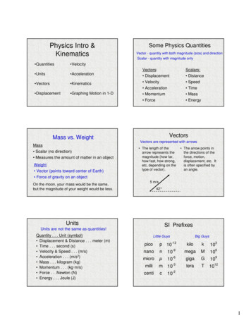
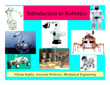
Jacobian for a rotational degree of freedomeffaxispointi-th joint Assume the i-thjoint is located at pi tW i (q) and has rotation axis 1 ai RW i (q) 0 0 We consider an infinitesimal variation δqi R of the ith joint and seehow an endeffector position peff φposeff,v (q) and attached vectorvecaeff φeff,v (q) change.19/62
Jacobian for a rotational degree of freedomeffConsider a variation δqi the whole sub-tree rotatesaxispointi-th joint Vector Jacobian: [an aeff ]vecJeff,v(q) . R3 n [a2 aeff ] [a1 aeff ][an (peff pn )] . [a2 (peff p2 )]posJeff,v(q)[a1 (peff p1 )] Position Jacobian: δpeff [ai (peff pi )] δqiδaeff [ai aeff ] δqi R3 n20/62
Jacobian for general degrees of freedom Every degree of freedom qi generates (infinitesimally, at a given q)– a rotation around axis ai at point pi– and/or a translation along the axis biFor instance:– the DOF of a hinge joint just creates a rotation around ai at pi– the DOF of a prismatic joint creates a translation along bi– the DOF of a rolling cylinder creates rotation and translation– the first DOF of a cylindrical joint generates a translation, its second DOFa translation We can compute all Jacobians from knowing ai , pi and bi for all DOFs(in the current configuration q Rn )21/62
Inverse Kinematics22/62
Inverse Kinematics problem Generally, the aim is to find a robot configuration q such that φ(q) y Iff φ is invertibleq φ-1 (y ) But in general, φ will not be invertible:1) The pre-image φ-1 (y ) may be empty: No configuration cangenerate the desired y 2) The pre-image φ-1 (y ) may be large: many configurations cangenerate the desired y 23/62
Inverse Kinematics as optimization problem We formalize the inverse kinematics problem as an optimizationproblemq argmin φ(q) y 2C q q0 2Wq The 1st term ensures that we find a configuration even if y is notexactly reachableThe 2nd term disambiguates the configurations if there are manyφ-1 (y )24/62
Inverse Kinematics as optimization problemq argmin φ(q) y 2C q q0 2Wq The formulation of IK as an optimization problem is very powerful andhas many nice properties We will be able to take the limit C , enforcing exact φ(q) y ifpossible Non-zero C -1 and W corresponds to a regularization that ensuresnumeric stability Classical concepts can be derived as special cases:– Null-space motion– regularization; singularity robutness– multiple tasks– hierarchical tasks25/62
Solving Inverse Kinematics The obvious choice of optimization method for this problem isGauss-Newton, using the Jacobian of φ We first describe just one step of this, which leads to the classicalequations for inverse kinematics using the local Jacobian.26/62
Solution using the local linearization When using the local linearization of φ at q0 ,φ(q) y0 J (q q0 ) ,y0 φ(q0 ) We can derive the optimum asf (q) φ(q) y 2C q q0 2W y0 y J (q q0 ) 2C q q0 2W f (q) 0 2(y0 y J (q q0 )) CJ 2(q q0 )T W qJ C (y y0 ) (J CJ W ) (q q0 )q q0 J ] (y y0 )with J ] (J CJ W )-1 J C W -1 J (JW -1 J C -1 )-1 (Woodbury identity)– For C and W I, J ] J (JJ )-1 is called pseudo-inverse– W generalizes the metric in q-space– C regularizes this pseudo-inverse (see later section on singularities)27/62
“Small step” application This approximate solution to IK makes sense– if the local linearization of φ at q0 is “good”– if q0 and q are close This equation is therefore typically used to iteratively compute smallsteps in configuration space qt 1 qt J ] (yt 1 φ(qt )) where the target yt 1moves smoothly with t28/62
Example: Iterating IK to follow a trajectory Assume initial posture q0 . We want to reach a desired endeff positiony in T steps:Input: initial state q0 , desired y , methods φpos and J posOutput: trajectory q0:T1: Set y0 φpos (q0 )// starting endeff position2: for t 1 : T do3:y φpos (qt-1 )// current endeff position4:J J pos (qt-1 )// current endeff Jacobian5:ŷ y0 (t/T )(y y0 )// interpolated endeff target6:qt qt-1 J ] (ŷ y)// new joint positions7:Command qt to all robot motors and compute all TW i (qt )8: end for01-kinematics:./x.exe -mode 2/329/62
Example: Iterating IK to follow a trajectory Assume initial posture q0 . We want to reach a desired endeff positiony in T steps:Input: initial state q0 , desired y , methods φpos and J posOutput: trajectory q0:T1: Set y0 φpos (q0 )// starting endeff position2: for t 1 : T do3:y φpos (qt-1 )// current endeff position4:J J pos (qt-1 )// current endeff Jacobian5:ŷ y0 (t/T )(y y0 )// interpolated endeff target6:qt qt-1 J ] (ŷ y)// new joint positions7:Command qt to all robot motors and compute all TW i (qt )8: end for01-kinematics:./x.exe -mode 2/3 Why does this not follow the interpolated trajectory ŷ0:T exactly?– What happens if T 1 and y is far?29/62
Two additional notes What if we linearize at some arbitrary q 0 instead of q0 ?φ(q) y 0 J (q q 0 ) ,y 0 φ(q 0 )q argmin φ(q) y 2C q q 0 (q 0 q0 ) 2Wq q 0 J ] (y y 0 ) (I J ] J) h ,h q0 q 0(1) What if we want to find the exact (local) optimum? E.g. what if we wantto compute a big step (where q will be remote from q) and we cannotnot rely only on the local linearization approximation?– Iterate equation (1) (optionally with a step size 1 to ensureconvergence) by setting the point y 0 of linearization to the current q – This is equivalent to the Gauss-Newton algorithm30/62
Where are we? We’ve derived a basic motion generation principle in robotics from– an understanding of robot geometry & kinematics– a basic notion of optimality31/62
Where are we? We’ve derived a basic motion generation principle in robotics from– an understanding of robot geometry & kinematics– a basic notion of optimality In the remainder:A. Discussion of classical conceptsB. Heuristic motion profiles for simple trajectory generationC. Extension to multiple task variables31/62
Discussion of classical concepts– Singularity and singularity-robustness– Nullspace, task/operational space, joint space– “inverse kinematics” “motion rate control”32/62
Singularity In general: A matrix J singular rank(J) d– rows of J are linearly dependent– dimension of image is d– δy Jδq dimensions of δy limited– Intuition: arm fully stretched33/62
Singularity In general: A matrix J singular rank(J) d– rows of J are linearly dependent– dimension of image is d– δy Jδq dimensions of δy limited– Intuition: arm fully stretched Implications:det(JJ ) 0 pseudo-inverse J (JJ )-1 is ill-defined! inverse kinematics δq J (JJ )-1 δy computes “infinite” steps! Singularity robust pseudo inverse J (JJ I)-1The term I is called regularization Recall our general solution (for W I)J ] J (JJ C -1 )-1is already singularity robust33/62
Null/task/operational/joint/configuration spaces The space of all q Rn is called joint/configuration spaceThe space of all y Rd is called task/operational spaceUsually d n, which is called redundancy34/62
Null/task/operational/joint/configuration spaces The space of all q Rn is called joint/configuration spaceThe space of all y Rd is called task/operational spaceUsually d n, which is called redundancy For a desired endeffector state y there exists a whole manifold(assuming φ is smooth) of joint configurations q:nullspace(y ) {q φ(q) y } We haveδq argmin q a 2W Jq δy 2Cq# J δy (I J # J)a ,J # W -1 J (JW -1 J C -1 )-1In the limit C it is guaranteed that Jδq δy (we are exacty on themanifold). The term a introduces additional “nullspace motion”.34/62
Inverse Kinematics and Motion Rate ControlSome clarification of concepts: The notion “kinematics” describes the mapping φ : q 7 y, whichusually is a many-to-one function. The notion “inverse kinematics” in the strict sense describes somemapping g : y 7 q such that φ(g(y)) y, which usually is non-uniqueor ill-defined. In practice, one often refers to δq J ] δy as inverse kinematics. When iterating δq J ] δy in a control cycle with time step τ (typicallyτ 1 10 msec), then ẏ δy/τ and q̇ δq/τ and q̇ J ] ẏ. Thereforethe control cycle effectively controls the endeffector velocity—this iswhy it is called motion rate control.35/62
Heuristic motion profiles36/62
Heuristic motion profiles Assume initially x 0, ẋ 0. After 1 second you want x 1, ẋ 0.How do you move from x 0 to x 1 in one second?The sine profile xt x0 12 [1 cos(πt/T )](xT x0 ) is a compromisefor low max-acceleration and max-velocityTaken from s toolbox/motion profile wizard/motionprofiles.htm37/62
Motion profiles Generally, let’s define a motion profile as a mappingMP : [0, 1] 7 [0, 1]with MP(0) 0 and MP(1) 1 such that the interpolation is given asxt x0 MP(t/T ) (xT x0 ) For exampleMPramp (s) s1MPsin (s) [1 cos(πs)]238/62
Joint space interpolation1) Optimize a desired final configuration qT :Given a desired final task value yT , optimize a final joint state qT to minimizethe functionf (qT ) qT q0 2W/T yT φ(qT ) 2C– The metric T1 W is consistent with T cost terms with step metric W .– In this optimization, qT will end up remote from q0 . So we need to iterateGauss-Newton, as described on slide 30.2) Compute q0:T as interpolation between q0 and qT :Given the initial configuration q0 and the final qT , interpolate on a straight linewith a some motion profile. E.g.,qt q0 MP(t/T ) (qT q0 )39/62
Task space interpolation1) Compute y0:T as interpolation between y0 and yT :Given a initial task value y0 and a desired final task value yT , interpolate on astraight line with a some motion profile. E.g,yt y0 MP(t/T ) (yT y0 )2) Project y0:T to q0:T using inverse kinematics:Given the task trajectory y0:T , compute a corresponding joint trajectory q0:Tusing inverse kinematicsqt 1 qt J ] (yt 1 φ(qt ))(As steps are small, we should be ok with just using this local linearization.)40/62
peg-in-a-hole demo41/62
Multiple tasks42/62
Multiple tasks43/62
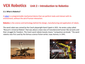
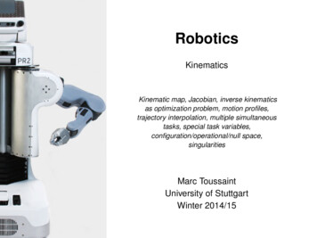
Multiple tasksRightHandpositionLeftHandposition44/62
Multiple tasks Assume we have m simultaneous tasks; for each task i we have:– a kinematic map φi : Rn Rdi– a current value φi (qt )– a desired value yi – a precision %i(equiv. to a task cost metric Ci %i I)45/62
Multiple tasks Assume we have m simultaneous tasks; for each task i we have:– a kinematic map φi : Rn Rdi– a current value φi (qt )– a desired value yi – a precision %i(equiv. to a task cost metric Ci %i I) Each task contributes a term to the objective functionq argmin q q0 2W %1 φ1 (q) y1 2 %2 φ2 (q) y2 2 · · ·q45/62
Multiple tasks Assume we have m simultaneous tasks; for each task i we have:– a kinematic map φi : Rn Rdi– a current value φi (qt )– a desired value yi – a precision %i(equiv. to a task cost metric Ci %i I) Each task contributes a term to the objective functionq argmin q q0 2W %1 φ1 (q) y1 2 %2 φ2 (q) y2 2 · · ·qwhich we can also write asq argmin q q0 2W Φ(q) 2q % (φ (q) y1 ) 1 1 %2 (φ2 (q) y2 ) where Φ(q) : . . RPidi45/62
Multiple tasks We can “pack” together all tasks in one “big task” Φ.Example: We want to control the 3D position of the left hand and of the righthand. Both are “packed” to one 6-dimensional task vector which becomes zeroif both tasks are fulfilled. The big Φ is scaled/normalized in a way that– the desired value is always zero– the cost metric is I Using the local linearization of Φ at q0 , J Φ(q0 ) q ,the optimum isq argmin q q0 2W Φ(q) 2q q0 (J J W )-1 J Φ(q0 ) q0 J # Φ(q0 )46/62
Multiple tasks We learnt how to “puppeteer a robot” We can handle many task variables(but specifying their precisions %i becomes cumbersome.) In the remainder:RightHandpositionLeftHandpositionA. Classical limit of “hierarchical IK” andnullspace motionB. What are interesting task variables?47/62
Hierarchical IK & nullspace motion In the classical view, tasks should be executed exactly, which means taking thelimit %i in some prespecified hierarchical order. We can rewrite the solution in a way that allows for such a hierarchical limit: One task plus “nullspace motion”:f (q) q a 2W %1 J1 q y1 2-1 q [W %1 J 1 J1 ] [W a %1 J1 y1 ] J1# y1 (I J1# J1 )a-1 -1 -1 -1J1# (W/%1 J 1 J1 ) J1 W J1 (J1 W J1 I/%1 ) Two tasks plus nullspace motion:f (q) q a 2W %1 J1 q y1 2 %2 J2 q y2 2q J1# y1 (I J1# J1 )[J2# y2 (I J2# J2 )a]-1 -1 -1 -1J2# (W/%2 J 2 J2 ) J2 W J2 (J2 W J2 I/%2 ) etc.48/62
Hierarchical IK & nullspace motion The previous slide did nothing but rewrite the nice solutionq J # Φ(q0 ) (for the “big” Φ) in a strange hierarchical way thatallows to “see” nullspace projection The benefit of this hierarchical way to write the solution is that one cantake the hierarchical limit %i and retrieve classical hierarchical IK The drawbacks are:– It is somewhat ugly– In practise, I would recommend regularization in any case (for numericstability). Regularization corresponds to NOT taking the full limit %i .Then the hierarchical way to write the solution is unnecessary. (However,it points to a “hierarchical regularization”, which might be numerically morerobust for very small regularization?)– The general solution allows for arbitrary blending of tasks49/62
Reference: interesting task variablesThe following slides will define 10 different types of task variables.This is meant as a reference and to give an idea of possibilities.50/62
PositionPosition of some point attached to link idimensiond 3parameterslink index i, point offset vkin. mapφposiv (q) TW i vJacobianposJiv(q)·k [k i] ak (φposiv (q) pk )Notation:– ak , pk are axis and position of joint k– [k i] indicates whether joint k is between root and link i– J·k is the kth column of J51/62
VectorVector attached to link idimensiond 3parameterslink index i, attached vector vkin. mapφveciv (q) RW i vJacobianvecJiv(q) Ai φveciv (q)Notation:– Ai is a matrix with columns (Ai )·k [k i] ak containing the joint axes orzeros– the short notation “A p” means that each column in A takes thecross-product with p.52/62
Relative positionPosition of a point on link i relative to point on link jdimensiond 3parameterslink indices i, j, point offset v in i and w in jkin. mappos-1 posφposiv jw (q) Rj (φiv φjw )JacobianposposposposJiv jw(q) Rj-1 [Jiv Jjw Aj (φposiv φjw )]Derivation:For y Rp the derivative w.r.t. a rotation around axis a isy 0 Rp0 R0 p Rp0 a Rp. For y R-1 p the derivative isy 0 R-1 p0 R-1 (R0 )R-1 p R-1 (p0 a p). (For details c/notes/3d-geometry.pdf)53/62
Relative vectorVector attached to link i relative to link jdimensiond 3parameterslink indices i, j, attached vector v in ikin. map-1 vecφveciv j (q) Rj φivJacobianvecvecJiv j(q) Rj-1 [Jiv Aj φveciv ]54/62
AlignmentAlignment of a vector attached to link i with a reference v dimensiond 1parameterslink index i, attached vector v, world reference v kin. mapφiv (q) v φvecivJacobianvecJiv (q) v JivNote:alignalignφalign 1 alignφalign 1 anti-alignφalign 0 orthog.55/62
Relative AlignmentAlignment a vector attached to link i with vector attached to jdimensiond 1parameterslink indices i, j, attached vectors v, wkin. map vecφiv jw (q) (φvecjw ) φivJacobian vecvec vecJiv jw (q) (φvecJjwjw ) Jiv φivalignalign56/62
Joint limitsPenetration of joint limitsdimensiond 1parameterskin. mapjoint limits qlow , qhi , margin mPn1 φlimits (q) mi 1 [m qi qlow ] [m qi qhi ]Jacobian11Jlimits (q)1,i m[m qi qlow 0] m[m qi qhi 0][x] x 0?x : 0[· · · ]: indicator function57/62
Collision limitsPenetration of collision limitsdimensiond 1parametersmargin mkin. mapφcol (q) JacobianJcol (q) 1m1mPK pak pbk ] PK pak pbk 0]k 1 [mk 1 [mpa pbpos kk( Jpposa J b ) pa pb pkkkkA collision detection engine returns a set {(a, b, pa , pb )Kk 1 } of potentialcollisions between link ak and bk , with nearest points pak on a and pbk on b.58/62
Center of gravityCenter of gravity of the whole kinematic structuredimensiond 3parameters(none)kin. mapφcog (q) PJacobianJ cog (q) Piimassi φposiciposmassi Jicici denotes the center-of-mass of link i (in its own frame)59/62
HomingThe joint angles themselvesdimensiond nparameters(none)kin. mapφqitself (q) qJacobianJqitself (q) InExample: Set the target y 0 and the precision % very low this taskdescribes posture comfortness in terms of deviation from the joints’ zeroposition. In the classical view, it induces “nullspace motion”.60/62
Task variables – conclusions There is much space for creativity in defining task variables! Many are extensions ofφpos and φvec and the Jacobians combinethe basic Jacobians.nearestdistanceLeftHandposition What the right task variables are to design/describe motion is a very hard problem! In what task space do humans control their motion? Possible to learn fromdata (“task space retrieval”) or perhaps viaReinforcement Learning. In practice: Robot motion design (including grasping) may require cumbersomehand-tuning of such task variables.61/62
Technical Reference: The four rotation axes of a quaternion joint:A quaternion joint has four DOFs. If it is currently in configuration q R4 , the ith DOFsgenerates (infinitesimally) a rotation around the axis 2ai p [ei q -1 ]1:3q2where ei R4 is the ith unit vector, is the concatenation of quaternions, q -1 the inversequaternion, q 2 the quaternion 2-norm (in case it is not normalized), and [·]1:3 pics thevector elements of the quaternion (derivation: see geometry notes). As for the hingejoint, these four axes are further transformed to world coordinates, ai RW j ai , if thequaternion joint is located in the coordinate frame j.62/62
Two “types of robotics”: 1) Mobile robotics – is all about localization & mapping 2) Manipulation – is all about interacting with the world 0) Kinematic/Dynamic Motion Control: same as 2) without ever making it to interaction. Typical manipulation robots (and animals) are kinem