Transcription
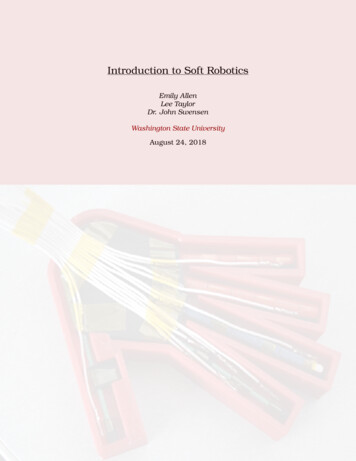
Introduction to Soft RoboticsEmily AllenLee TaylorDr. John SwensenWashington State UniversityAugust 24, 2018
M3 RoboticsIntroduction to Soft RoboticsTABLE OF CONTENTSNomenclature21 Introduction32 Background Theory2.1 Stress . . . . . . . . . . . .2.2 Strain . . . . . . . . . . . .2.3 Stress-Strain Relationship2.4 Bending Moment . . . . . .2.5 Moment of Inertia . . . . .2.6 Smart Materials . . . . . .2.7 Electrical Resistance . . .334456773 Soft Robotic Hand3.1 Design Features . . . . . . . . . . . . . . . . . . . . . . . . . . . . . . . . . . .88.4 Hand Assembly4.1 Necessary Equipment . . . . . .4.2 Materials . . . . . . . . . . . . .4.3 3D Printing . . . . . . . . . . . .4.3.1 Printer Setup . . . . . . .4.3.2 Printing the Components4.4 Assembly Instructions . . . . . .101010111113175 Controlling the Hand5.1 Setup . . . . . . . . . . . .5.2 Nitinol Thumb . . . . . . .5.3 Nitinol Index Finger . . . .5.4 Field’s Metal Middle Finger5.5 PCL Ring Finger . . . . . .5.6 PCL Pinky Finger . . . . . .5.7 Advanced Control . . . . .2727272727282828.List of Figures29List of Tables29Washington State University1
M3 RoboticsIntroduction to Soft RoboticsNOMENCLATUREAlloyCritical temperatureCross section(Electrical) currentDirectly proportionalDistal jointElastic RegionGood (electrical) conductorInversely proportionalJoule heating(Bending) momentMoment of inertiaPhalanx (phalanges)Poor (electrical) conductor(Electrical) resistanceShape memory effectSmart materialStrainStressYield pointA mixture of metallic materialsTemperature at which phase transformation occurs in asmart materialThe shape/area of a beam exposed if cut perpendicularto its lengthThe flow of electrical charge through a material via electronsWhen one variable increases the other increases by thesame factorThe joint in the finger closest to the finger tipRange of deformation where stress and strain are directly proportional; deformation is impermanentA material that greatly resists the flow of electrical current or traveling electronsWhen one variable increases the other decreases andvice versaDissipating heat by passing a current through a resistorThe extent to which a force causes bending of a body(usually a rod or beam)The resistance of a particular cross section to bendingabout a specific axisA bone (or bones) of the fingers or toesA material in which the flow of electrical current or traveling electronsOpposition to movement of electrons or passage of electrical currentThe ability of a material to return to its original shapewhen heated to a critical temperatureA material whose properties (strength, stiffness, conductivity, etc.) change significantly when its environment (temperature, electric field, etc.) changesObject’s response to applied stressForce per unit area within material bodyPoint at which chemical bonds begin breaking and permanent deformation occursWashington State University2
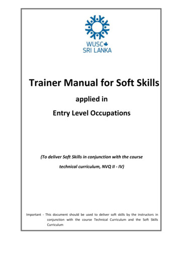
Introduction to Soft Robotics1.M3 RoboticsINTRODUCTIONMost traditional robots are used in isolated environments because their size, heaviness,and rapid movement can be dangerous or unhelpful for interaction with humans. There isa growing interest and need for technology that allows capable robots to be used alongsidehumans for application domains including home health care, medical procedures andinterventions, factory automation, and military personnel support. The main challengein developing robots of this nature is achieving flexibility and dexterity without sacrificingthe strength necessary to perform useful tasks such as lifting a person out of bed.Studying the brilliantly complex design of the human body proves that such capabilitiesare possible. Unfortunately, current technology does not allow for exact replication of thecomplicated tissue in the human body which can be both strong and flexible. However,the basic ideas of rigid bones with joint motion controlled by tendons serves as inspirationfor robot technology.Figure 1: Diagram of Human Finger.Consider the human hand, for example, where fingers, are capable of straightening andcurling inward with great force. Strong tendons, as seen in Figure 1, pull on the bonesof the finger when muscles in the forearm contract. These long tendons provide highstrength, and they control most of the motion of the fingers. Smaller muscles in thehand control small movements such as side-to-side motion at the base of the fingers.Similar design concepts from the human hand may be incorporated into a robotic handwith similar capabilities.2.BACKGROUND THEORYMany of the biological concepts may be integrated in a robotic hand with similar capabilities using simple engineering principles. Understanding the engineering principlesbehind the design of the hand is the first step in creating a functional replica.2.1STRESSStress is defined as the force per unit area within a material with an applied load. Itrepresents the force experienced relative to the size of the object being stressed. Forexample, consider two pieces of wire that are identical except in their diameter. If bothwires are pulled with the same force, which one will experience greater stress? Intuitively,we can expect that the narrow wire experiences higher stress than the thick wire becausethe thin wire has less material (or cross-sectional area) to share the load with.Washington State University3
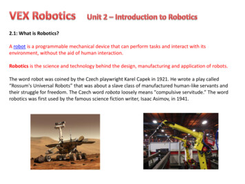
Introduction to Soft RoboticsM3 RoboticsAlternatively, we can consider the question from a mathematical perspective. When theforce is applied in tension (pulling the material along its axis), the stress is calculatedfrom F/A, where F is the applied force and A is the cross-sectional area of the object.Since the area appears on the bottom of the fraction, we can say that the stress and thecross-sectional area are inversely proportional. This means that when the area increases,the stress decreases; and when the area decreases, the stress increases. Since the thinwire has a smaller cross-sectional area, it experiences higher stress when pulled with thesame force as the thick wire.2.2STRAINStrain is the object’s response to an applied force; it can be thought of as a measure ofelongation relative to the length of the object. Consider the same two wires being pulledwith the same force again. Regardless of what the wire is made of, we can expect thatthey will stretch at least a little. The thin wire will stretch more under the same loadas the thick wire, so the thin wire is said to experience higher strain. The wire’s strainrepresents how much the wire stretches; it depends on the stiffness of the material andthe stress experienced by the object.2.3STRESS-STRAIN RELATIONSHIPOften in engineering, a stress-strain curve is used to characterize the properties of amaterial. To make a stress-strain curve, data is usually collected from a simple tensiontest experiment. Similar to the wire example, a rod of the material is gripped at both endsby a machine that pulls the rod in tension. As the rod is slowly stretched, the tension inthe rod and the amount of stretching are measured simultaneously.Figure 2: Typical stress-strain curve for metal material.These tension (force) and stretching measurements can then be converted into stress andstrain values using the dimensions of the rod. Plotting the stress on the Y-axis with thestrain on the X-axis gives us a graph that characterizes the material’s behavior underdifferent loadings. Figure 2 shows a typical stress-strain curve for a metal material.Washington State University4
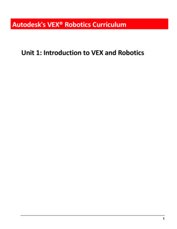
Introduction to Soft RoboticsM3 RoboticsThe first portion of the curve is linear; this is called the elastic region. When materials arestressed within the elastic range, the stress and strain are directly proportional, meaningthat if the force applied (or stress) is doubled, the resulting strain (or elongation) is alsodoubled. Elastic deformation is reversible, so the material will return to its original lengthwhen the tension is released.The point at the end of the linear region is called the yield point. Stressing the materialbeyond the yield point causes some permanent deformation as chemical bonds begin tobreak. As the material is stretched beyond the elastic region, the relationship betweenthe stress and strain changes such that a large increase in elongation (strain) is causedby increasing the stress (or applied force) only slightly.2.4BENDING MOMENTFigure 3: Example of a bending moment caused by a downward force applied at the center of abeam.A moment measures the extent to which a force causes bending of a body (usually a rodor beam). A typical example of a bending moment is shown in Figure 3, where a simplebeam experiences a bending moment caused by a downward force applied at the center.In the case of the human finger, the tendon running along the finger bone causes abending moment in the joints which makes the finger bend. The moment is calculatedfrom F d, where F is the applied force and d is the perpendicular distance from the forceto the joint. The bending moment is thus dependent on the distance from the force tothe joint, meaning that the offset of the tendon from the bones is crucial.Figure 4: Two joint designs demonstrating the importance of the offset between the tendon andthe joint/bones.For example, consider the two joint scenarios shown in Figure 4. Notice how changingthe offset of the tendon from the bones/joint affects the bending moment on the joint.Washington State University5
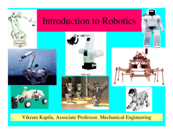
M3 RoboticsIntroduction to Soft RoboticsSince the moment is directly proportional to d, applying the same force to each setup willcause a larger bending moment about the joint in the setup on the left. This means that alarger force is required to bend the finger if the tendon runs very close to the bones/joint.Figure 5: Bent joint with increased bending moment due to increased distance between tendonand joint.The distance between the tendon and joint is also affected by the angle of the joint. Asseen in Figure 5, d (and thus M) increases when the joint is bent. This means thatthe same force can cause a larger bending moment in the joint when it is bent. For thisreason, the human fingers are stronger when they are curled than when they are straight.2.5MOMENT OF INERTIA(a)(b)Figure 6: (a) Bending inertia of ruler affected by orientation. (b) Increased height significantlyincreases the bending inertia.The moment of inertia represents the resistance of a particular cross section to bendingabout a specific axis. Consider the bending of a ruler as shown in Figure 6a. Bendingis much easier in one direction than the other. This is because the ruler has a differentmoment of inertia about the different axes.When studying the bending of the human finger, the moment of inertia plays a significantrole in the force required to bend the finger. In general, increasing the cross-sectionalarea (especially the height) of the member increases its resistance to bending. Thus, agreater force is required to bend thick fingers due to their higher bending inertia.Washington State University6
Introduction to Soft Robotics2.6M3 RoboticsSMART MATERIALSSmart materials are materials whose properties (strength, stiffness, conductivity, etc.)change significantly when their environment (temperature, electric field, etc.) changes.These types of materials are especially useful for soft robotics because they can mimicbiological members such as human muscle tissue which is flexible but can become strongand rigid when contraction occurs.Nitinol is a smart material with unique properties that lend themselves well to the softrobotics domain. It is an alloy (mixture) of nickel and titanium with properties that changeat a specific critical temperature. Above the critical temperature, the Nitinol becomesvery stiff and thus resistant to bending. Below the critical temperature, it undergoesa phase transformation making it bendable and significantly softer. When the materialis reheated above its critical temperature, it returns to its initial shape. This uniquebehavior is called the shape memory effect.Another smart material of interest is Field’s metal. Field’s metal is composed of a mixtureof Tin, Indium, and Bismuth combined in a specific ratio such that the Field’s metalmelts at a very low temperature (62 C). This low melting-temp metal is useful for roboticsapplications because it is stiff in its solid state (above 62 C) and liquid (0 stiffness) belowits melting point.Similarly, PCL (polyacrylonitrile) is a plastic that can be considered a smart materialbecause is softens and melts at very low temperatures. The plastic is rigid at room temperature but softens and melts around 50 C.2.7ELECTRICAL RESISTANCERemembering from chemistry class, electrons have a negative charge while protons holda positive charge. The flow of negative charge as electrons travel through a material iscalled electrical current. Some materials, including most metals, allow electrons to passthrough easily; we call these materials good conductors. Good conductors have low electrical resistance because they do not resist the flow of electrons. Other materials suchas plastics and some ceramics hold electrons tightly and thus resist the flow of electrons.These materials have a high electrical resistance and are classified as poor conductors.Good conductors (low electrical resistance) are usually desirable for efficiency becauseresistance slows the charge transfer and causes energy loss. However, in some casesenergy loss is a desirable outcome as it produces heat. Similar to frictional resistance ona moving object, energy lost through electrical resistance also causes energy to be dissipated as heat. This principle is called Joule heating. The typical baseboard heaters foundin many houses operate from this simple principle where a current is passed through along, thin heating element with a high electrical resistance to maximize heat dissipation.In the case of the soft robotic hand, the stiffness of the joints is controlled by alteringthe individual joint temperatures. This localized heating can be easily achieved usingthe Joule heating principle. Nichrome is a high resistance metal that is often used forheating elements. The joints can be heated individually by passing current throughNichrome wire that is wrapped around insulated Nitinol, Field’s metal, or PCL joints.Washington State University7
Introduction to Soft Robotics3.M3 RoboticsSOFT ROBOTIC HANDFigure 7: Soft robotic hand featuring multiple smart materials.The soft robotic hand is designed to mimic cunning biological features such as tendons,bones, and flexible tissue. Figure 7 shows the design of a simple soft robotic hand. Eachof the engineering principles discussed above (stress, strain, bending moment, momentof inertia) are factors that play into the functionality of the design.3.1DESIGN FEATURESSimilar to the human hand, the soft robotic hand is capable of curling and extendingthe fingers with enough force to grasp items with dexterity and precision. The fingersdemonstrate 3 different smart materials that can be used to achieve the desired strengthand joint controllability. The hand is designed to be light, soft, and safe with no sharpedges or pinching hazards. The fingernails and grippy silicone allow it to grasp items ofvarious shapes, sizes, and textures.The palm is 3D printed with ABS filament to maintain rigidity and support each of the fingers and corresponding tendons. The human hand utilizes two major sets of tendons tocontrol the finger movements; one set of tendons curls the fingers and the other straightens them. The use of Nitinol, Field’s metal, PCL, and Silicone in the soft robotic handallows for complete control of the fingers using just one set of tendons.Washington State University8
Introduction to Soft RoboticsM3 RoboticsThe fingers curl when the tendons are pulled and the finger joints are held at the appropriate temperature to allow bending at the joints. A Nitinol thumb and index fingerextend from the palm, providing strength at high temperatures and flexibility in the jointsat low temperatures. The middle finger consists of a Field’s metal rod that can be meltedat the joints to allow the finger to curl when the joints are held at a high temperature.The ring and pinky fingers are comprised of PCL rods that may be melted at the joints toallow bending. Any of the fingers may be curled by pulling the corresponding tendon andholding the joints at an appropriate temperature to achieve flexibility in the particularsmart material.Unlike the human hand, which requires a second set of tendons on the back of thehand to straighten the fingers, the fingers in the soft robotic hand straighten themselveswith the appropriate temperature stimulus. Since the Nitinol is a shape memory alloy,the thumb and index finger return to their original (straight) shape when the Nitinol isheated above the critical temperature and the tendon tension is released. The Field’smetal and PCL do not exhibit the shape memory effect, but their flexibility in the liquidstate allows them to straighten without actuation. Because the silicone rubber is castwith the fingers straight, the elasticity of the silicone causes the middle, ring, or pinkyfinger to straighten when the Field’s metal or PCL is melted at the joints and the tensionin the tendon is released.The ABS 3D printed rigid links mimic the bones of the fingers, preventing bending of theNitinol rods except at the joints. The middle, ring, and pinky finger do not need rigidlinks to prevent bending between the joints because the heating elements are locatedonly at the joints and do not melt the PCL or Field’s metal except at the joints, so thefingers remain rigid between joints. The tendon sheaths prevent the tendons from tearingthrough the silicone and hold the tendons at an offset from the Nitinol rods to increasethe bending moment applied by the cable tension. The entire assembly is encased insilicone to protect the components and replicate the texture of the human hand. Thesilicone is notched at the finger joints to decrease the bending inertia and the friction onthe tendons. The fingertips/nails aid in the grasping of objects and also provide a tyinglocation for the ends of the tendons. This helps distribute the load from the tendonsacross the surface of the finger tips.Localized heating of the smart materials at the finger joints is achieved by passing electrical current through Nichrome wire wrapped around the smart material at the joints.Because Nitinol and Field’s metal are conductive materials, a thin layer of insulation prevents direct contact between the Nichrome and the smart material. Since the Nichromehas a high electrical resistance, the current would prefer to pass through the Nitinol orField’s metal (lower resistance) if given the chance. The insulation prevents the currentfrom traveling through the Nitinol or Field’s metal, forcing it to flow through the higherresistance Nichrome wire which dissipates much more heat to stimulate the temperatureinduced transformation of the Nitinol or Field’s metal.The pointer finger is wired with separate heating elements for each joint so that the jointsmay be controlled individually. The thumb is equipped with two tendons so that it maybe moved in two different directions, hence the thumb link with two separate tendonsheaths. For simplicity, the last three fingers have only one heating element per fingerthat heats all 3 joints with only one connection to the power supply. Thus, the 3 joints inthe middle, ring, and pinky finger can only be moved in synchrony. Wiring these jointsWashington State University9
Introduction to Soft RoboticsM3 Roboticswith separate Nichrome elements would allow individual joint control but would requiremore wires and added complexity.The movement of the hand may be controlled by manually connecting the heating elements to the power supply and pulling on the tendons by hand. Alternatively, for moreadvanced control, a control system may be implemented to pull the tendons with servomotors and heat the joints to desired temperatures via relay switches that modulateon/off when based on feedback from temperature sensors near the joints.4.HAND ASSEMBLY4.1NECESSARY EQUIPMENT 3D printer (Minimum 6.125”x6.125”x1” build volume) Wire cutters Hand drill with drill bits Calipers Heat gun Pump and vacuum chamber (optional) Pointed tweezers Power supply (2 A, 20 V) with alligator leads4.2MATERIALS Ninjaflex filament (Ø3mm) ABS filament (Ultimaker Ø3mm) 3 ft PCL filament (FILAMENTS.CA’s 2.85mm Low Temperature PCL Filament) 6” Nitinol wire (Ø1.91mm, shape memory) 2lb package of Silicone (Dragon Skin, 20 medium cure time) Nichrome 80 wire (32 AWG) 14g Field’s metal (Roto144F Low Melt Fusible Ingot Alloy (Field’s Metal)) 15 ft Insulated copper wire (24-26 AWG, single strand, 105 C) 14 Molex female crimp terminals (18-24 AWG) Wire shrink insulation 2:1 heat shrink tubing (Ø1mm, Ø2mm, Ø4mm) Kapton tape or other electrical tape 6 ft Braided fishing line (Ø0.46mm, 100lb)Washington State University10
Introduction to Soft Robotics4.3M3 Robotics3D PRINTINGWe will be using Cura to print the parts for the hand. Cura is an open-source softwarefor “slicing” 3D models into many two dimensional slices for layer by layer printing on our3D printer. As Cura supports many 3D printers with custom profiles, the instructionsincluded here can be applied to most other machines.4.3.1Printer Setup1. Download and Install CuraFigure 8: Download Cura, an Open-Source Slicer, from the Official WebsiteNavigate to : oftwareand click “Download for free”. Once downloaded, proceed to install the software onyour computer. When prompted to choose components, leave the default optionsselected, and click Install.Washington State University11
M3 RoboticsIntroduction to Soft Robotics2. Profile Setup(a)(b)Figure 9: Default Profiles (a) & Manual Configuration (b)In your first startup of Cura, you will be prompted to select your 3D Printer Profile. These profiles contain settings tailored to your specific printer, generally by themanufacturer, and contains sub-profiles for commonly used materials.If you are using a printer currently listed in in these profiles, select it and click AddPrinter then skip to step #4. Otherwise, select the Custom, click on “Custom FDMPrinter”. When prompted for Machine Settings, click “Finish”3. Installing the latest Prusa i3 MK3 ProfileFigure 10: Install the latest Prusa MK3 profileAs the Prusa i3 MK3 does not currently have a default profile, we will need to download and manually install the latest profile. Prusa has created a step by step guidefor this process. Navigate to https://www.prusa3d.com/drivers/ and click on “CuraSettings”, following the procedure to install the printer, layer height, material, andbackground profiles. Note that while we are provided with a profile for ABS, PLA,and PET, there is not one for NinjaFlex. We will have to create that profile manuallylater.Washington State University12
M3 RoboticsIntroduction to Soft Robotics4. Learning to use CuraThere are numerous resources available for learning the basics of Cura. If you haveexperience using other slicing software already, then the quick start guide availablefrom Ultimaker is a good starting point. If this is your first time using a slicer and3D printer, then their master guide is worth a read. This guide will assume fromhere on that you have familiarized yourself with Cura.Quick Start quick%20start%20guide.pdfMastering ering-cura4.3.2Printing the Components1. Palm(a) The Palm(b) Palm SettingsFigure 11: Palm & Print SettingsThe palm, shown above in Figure 11a, is a single part which contains internal channels for tendons to pass through, along with inserts for the nitinol, fields metal, andPCL. Two of these inserts will require supports to ensure dimensional accuracy.Select the following default profiles: Material Profile:Prusa ABS Layer Profile:MK3 0.15 OptimalEnable custom settings and scroll to “Support”, changing “Support Overhang Angle”to 79 , as shown in Figure 11b. This will only print supports where required andminimize post print cleanup. The Palm is now ready to print, and once done, thesupports can be removed with a pair of tweezers or pliers.Washington State University13
Introduction to Soft RoboticsM3 Robotics2. Links & SheathsThe parts most likely to fail to print are the links and sheaths. These componentshave very small areas with which to adhere to the print bed. Therefore, we will printthese components in batches, reasonably close together, and use brims instead ofthe default skirts.Load up one of each Link, and Sheath, then right click on each component andselect “multiply”. You will need to print 2 Rigid End Caps, 2 Rigid Links, 9 TendonSheaths, and 1 Thumb Link.Select the following default profiles: Material Profile:Prusa ABS Layer Profile:MK3 0.1 DetailFigure 12: Build Plate Adhesion SettingsEnable Custom Settings, and scroll to “Build Plate Adhesion”, changing “Build PlateAdhesion Type” from Skirt to Brim. Leave all other settings as their defaults. Oncethe parts have been printed, the brim can be peeled off from each part, and a lightsandpaper can be used to smooth out any rough edges.Figure 13: A tight placement will reduce print time & failuresArrange the parts on the print bed so that they are close to one another, but notoverlapping. You can have Cura auto arrange, which will use the build plate adhesion settings from Figure 12 to set initial placements, then shift them closer togethermanually, if necessary. You should have a build placement similar to that shown inFigure 13.Washington State University14
M3 RoboticsIntroduction to Soft Robotics3. Finger Tips(a)(b)Figure 14: Incorrect Orientation (a) & Correct Orientation (b)Import the finger tip model, and ensure that the model is oriented as shown inFigure 14b. Multiply the model until you have 5. We will use the same settingsfrom the previous step, but placement of the models does not need to be packed asbefore.When removing the finger tips from the print bed, it is possible that the small clip,indicated by the arrow in Figure 14a, will break off if too much force is used inremoval. To ensure the best chance of a successful removal, wait for the print bedto completely cool first. The bed, having been heated during the printing process,will naturally contract as it cools, and the parts are easier to remove as a result.Print extra finger tips if needed to replace broken ones.4. Silicone & Field’s Metal Molds(a)(b)Figure 15: Field’s Metal Mold (a) & Silicone Hand Mold (b)Both molds used in the construction of the hand are going to be printed out of aTPU material known as Ninja-flex. On a printer such as the Prusa, we cannot printthe material as quickly as ABS, because it is easily deformed at low pressures, suchas being forced through a nozzle.Washington State University15
M3 RoboticsIntroduction to Soft Robotics(a) Speed Settings(b) Temperature SettingsFigure 16: Mold Print SettingsSelect the following default profiles: Material Profile:Prusa ABS Layer Profile:MK3 0.1 DetailChange the print speed settings to those shown in Figure 16a. This will increaseprint time, but reduce peak pressure being exerted on the filament.The temperature in the default profile for ABS is too high, as the printing temperature for NinjaFlex is about 220C. Set the temperatures as shown in Figure 16b;additionally, disable retraction.Disabling retraction means that the printer will never try to pull the filament backout when it is changing layers or passing over empty space or another part of theobject. By default, the profile does not pass over printed areas of the object. Themolds are mostly stacked walls, therefore there is little need for travel across largeopen spaces.With this filament, we do not want to use a brim, skirt, or raft as these supports arevery difficult to separate from the main body. Under ”Build Plate Adhesion”, seenback in Figure 13, change the type from skirt or brim to None.Washington State University16
M3 RoboticsIntroduction to Soft Robotics4.4ASSEMBLY INSTRUCTIONS1. Print palm, rigid links, rigid end caps, thumb link, thumb end cap, tendon sheaths,Field’s metal mold, and silicone mold according to 3D printing instructions above.2. For the PCL fingers, cut 3 strands of PCL filament to 2.74” each for the pinky fingerand 5 strands to 3.09” each for the ring finger. Heat the strands with a heat gununtil they soften and become slightly translucent. Roll the strands together by handon a flat surface until the filaments merge together to form a uniform cylindrical rodfor both fingers.3. For the Field’s metal middle finger, heat about 14 g of Field’s metal with a heat gunor on a hot plate just until completely melted. Pour the liquid metal into the Field’smetal mold until filled and allow to cool. Remove from the mold once cooled andinspect for air bubbles. If substantial voids exist, melt the rod and repour it in themold until a uniform rod is formed.4. For the Nitinol fingers, cut one length of Nitinol wire to 3.16” for the index fingerand one length to 2.61” for the thumb.Table 1: Material lengths for fingers.FingerMaterialExposed LengthTotal LengthPinkyRingMiddleP
Introduction to Soft Robotics M3 Robotics 2.6 SMART MATERIALS Smart materials are materials whose properties (strength, stiffness, conductivity, etc.) change significantly when their environment (temperature, electric field, etc.) changes. These types of materials are especially useful