Transcription
ECE 470Introduction to RoboticsLab ManualJonathan K. HolmJifei XuYinai FanUniversity of Illinois at Urbana-ChampaignFall 2016
ii
Acknowledgementsiii
iv
Contents1 Introduction to1.1 Objectives .1.2 References .1.3 Task . . . .1.4 Procedure .1.5 Report . . .1.6 Demo . . .1.7 Grading . .11112333.5555788993 Forward Kinematics3.1 Objectives . . . . . . . . . . . . .3.2 References . . . . . . . . . . . . .3.3 Tasks . . . . . . . . . . . . . . .3.3.1 Physical Implementation .3.3.2 Theoretical Solution . . .3.3.3 Comparison . . . . . . . .3.4 Procedure . . . . . . . . . . . . .3.4.1 Physical Implementation .3.4.2 Theoretical Solution . . .111111121212121313162 The2.12.22.32.42.52.62.72.8the Rhino. . . . . . . . . . . . . . . . . . . . . . . . . . . . . . . . . . . . . . . . . . .Tower of HanoiObjectives . . . .Pre-Lab . . . . .References . . . .Task . . . . . . .Procedure . . . .Report . . . . . .Demo . . . . . .Grading . . . . .v
viCONTENTS.171718184 Inverse Kinematics4.1 Objectives . . . . . . . . . .4.2 Reference . . . . . . . . . .4.3 Tasks . . . . . . . . . . . .4.3.1 Solution Derivation .4.3.2 Implementation . . .4.4 Procedure . . . . . . . . . .4.5 Report . . . . . . . . . . . .4.6 Demo . . . . . . . . . . . .4.7 Grading . . . . . . . . . . .212121212123232626265 Image Processing5.1 Objectives . . . . . . . . . . . . . . . . . . .5.2 References . . . . . . . . . . . . . . . . . . .5.3 Tasks . . . . . . . . . . . . . . . . . . . . .5.3.1 Separating Objects from Background5.3.2 Associating Objects in the Image . .5.4 Procedure . . . . . . . . . . . . . . . . . . .5.4.1 Separating Objects from Background5.4.2 Associating Objects in the Image . .5.5 Report . . . . . . . . . . . . . . . . . . . . .5.6 Demo . . . . . . . . . . . . . . . . . . . . .5.7 Grading . . . . . . . . . . . . . . . . . . . .2727272828282828313636366 Camera Calibration6.1 Objectives . . . . . . . . . . .6.2 References . . . . . . . . . . .6.3 Tasks . . . . . . . . . . . . .6.3.1 Object Centroids . . .6.3.2 Camera Calibration .6.3.3 Bonus: Pick and Place6.4 Procedure . . . . . . . . . . .6.4.1 Object Centroids . . .6.4.2 Camera Calibration .6.4.3 Pick and Place . . . .37373738383838393939423.53.63.73.4.3 ComparisonReport . . . . . . .Demo . . . . . . .Grading . . . . . .
CONTENTS6.56.66.7viiReport . . . . . . . . . . . . . . . . . . . . . . . . . . . . . . .Demo . . . . . . . . . . . . . . . . . . . . . . . . . . . . . . .Grading . . . . . . . . . . . . . . . . . . . . . . . . . . . . . .A Mathematica and RoboticaA.1 Mathematica Basics . . . . . . . . . . . . . . . . . . . .A.2 Writing a Robotica Source File . . . . . . . . . . . . . .A.3 Robotica Basics . . . . . . . . . . . . . . . . . . . . . . .A.4 Simplifying and Displaying Large, Complicated MatricesA.5 Example . . . . . . . . . . . . . . . . . . . . . . . . . . .A.6 What Must Be Submitted with Robotica Assignments .434343.45454647474951B C Programming in ROSB.1 Overview . . . . . . . . . . . . . . . . . .B.2 ROS Concepts . . . . . . . . . . . . . . .B.3 Before we start. . . . . . . . . . . . . . .B.4 Create your own workspace . . . . . . . .B.5 Running A Node . . . . . . . . . . . . . .B.6 Simple Publisher and Subscriber Tutorial.53535354565757C Notes on Computer VisionC.1 OpenCV in ROS . . . . . . . . . . . . .C.1.1 Camera Driver . . . . . . . . . .C.1.2 Accessing Image Data . . . . . .C.1.3 Some Useful OpenCV FunctionsC.2 Introduction to Pointers . . . . . . . . .C.3 Simplifying Camera Calibration . . . . .59595960636465.
viiiCONTENTS
PrefaceThis is a set of laboratory assignments designed to complement the introductory robotics lecture taught in the College of Engineering at the University of Illinois at Urbana-Champaign. Together, the lecture and labsintroduce students to robot manipulators and computer vision along withRobot Operating System (ROS) and serve as the foundation for more advanced courses on robot dynamics and control and computer vision. Thecourse is cross-listed in four departments (Computer Science, Electrical &Computer Engineering, Industrial & Enterprise Systems Engineering, andMechanical Science & Engineering) and consequently includes students froma variety of academic backgrounds.For success in the laboratory, each student should have completed a coursein linear algebra and be comfortable with three-dimensional geometry. Inaddition, it is imperative that all students have completed a freshman-levelcourse in computer programming. Spong, Hutchinson, and Vidyasagar’stextbook Robot Modeling and Control (John Wiley and Sons: New York,2006) is required for the lectures and will be used as a reference for manyof the lab assignments. We will hereafter refer to the textbook as SH&V inthis lab manual.These laboratories are simultaneously challenging, stimulating, and enjoyable. It is the author’s hope that you, the reader, share a similar experience.Enjoy the course!ix
xCONTENTS
LAB 1Introduction to the Rhino1.1ObjectivesThe purpose of this lab is to familiarize you with the Rhino robot arm, thehard home and soft home configurations, the use of the teach pendant, andthe function of encoders. In this lab, you will: move the Rhino using the teach pendant send the Rhino to the hard home and soft home configurations store sequences of encoder counts as “programs” demonstrate at sequence of motions that, at minimum, places oneblock on top of another.1.2References Use of the teach pendant: Rhino Owner’s Manual chapters 3 and 4. How to edit a motion program: Rhino Owner’s Manual chapter 5.1.3TaskUsing the teach pendant, each team will “program” the Rhino to pick andplace blocks. The program may do whatever you want, but all programsmust stack at least one block on top of another. Programs must begin andend in the hard home position.1
2LAB 1. INTRODUCTION TO THE RHINO1.4Procedure1. Turn on the Rhino controller (main power and motor power).2. Put controller in teach pendant mode.3. Experiment with the arm, using the teach pendant to move the motorsthat drive each axis of the robot. Observe that the teach pendant will display a number for eachmotor you move. These numbers correspond to encoder measurements of the angle of each motor axis. By default, the teachpendant will move each motor 10 encoder steps at a time. Youcan refine these motions to 1 encoder step at a time by pressingSHIFT Slow on the teach pendant.4. SHIFT Go Hard Home: moves the arm to a reference configurationsbased on the physical position of the motor axes and resets all encodersto zero.5. LEARN: Enter learn mode on the teach pendant.6. Program a sequence of motions: move a motor, ENTER, move anothermotor, ENTER, . Beware storing multi-axis motions as a single “step” in your program. The Rhino may not follow the same order of motor movements when reproducing your step. Break up dense multi-axismotions (especially when maneuvering near or around an obstacle) into smaller, less-dense steps. Store gripper open/close motions as separate steps.7. The final motion should be: Go Soft Home, ENTER. The soft homeposition simply seeks to return all encoders to zero counts. If nothing has disturbed your Rhino, Go Soft Home should result in virtually the same configuration as Go Hard Home. TheRhino will not allow you to use Go Hard Home as a “step” in yourmotion program.
1.5. REPORT3 If your robot has struck an obstacle, the encoder counts will nolonger accurately reflect the arm’s position with respect to thehard home position. If you use soft home to return the robot tozero encoder counts, it will be a different configuration than hardhome. In such an instance, you will need to Go Hard Home torecalibrate the encoders.8. END/PLAY: enter “play” mode.9. RUN: executes the sequence of motions you have stored in the teachpendant’s memory.1.5ReportNone required. Finish pre-lab for lab 2.1.6DemoShow your TA the sequence of motions your team has programmed. Remember, your program must successfully stack at least one block on another.1.7GradingGrades will be pass/fail, based entirely on the demo.
4LAB 1. INTRODUCTION TO THE RHINO
LAB 2The Tower of Hanoi2.1ObjectivesThis lab is an introduction to controlling the Rhino robots using the cppprogramming language. In this lab, you will: record encoder counts for various configurations of the robot arm using prewritten cpp functions, move the robot to configurations basedon encoder counts order a series of configurations that will solve the Tower of Hanoiproblem.2.2Pre-LabRead ”A Gentle Introduction to ROS ”, available online, Specifically: Chapter 2: 2.4 Packages, 2.5 The Master, 2.6 Nodes, 2.7.2 Messagesand message types. Chapter 3 Writing ROS programs.2.3References Consult Appendix B of this lab manual for details of ROS and cppfunctions used to control the Rhino. ”A Gentle Introduction to ROS ”, Chapter 2 and 3.5
6LAB 2. THE TOWER OF HANOI A short tutorial for ROS by Hyongju Park. https://sites.google.com/site/ashortrostutorial/ Since this is a robotics lab and not a course in computer science ordiscrete math, feel free to Google for solutions to the Tower of Hanoiproblem.1 You are not required to implement a recursive anoi.shtml (an active site, as of this writing.)
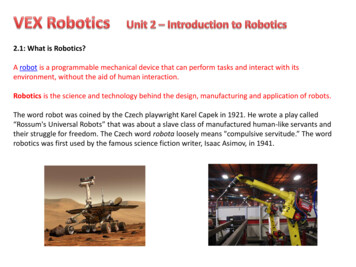
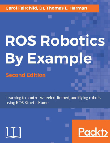
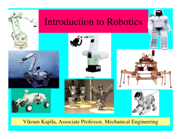
2.4. TASK7Figure 2.1: Example start and finish tower locations.Figure 2.2: Examples of a legal and an illegal move.2.4TaskThe goal is to move a “tower” of three blocks from one of three locationson the table to another. An example is shown in Figure 2.1. The blocksare numbered with block 1 on the top and block 3 on the bottom. Whenmoving the stack, two rules must be obeyed:1. Blocks may touch the table in only three locations (the three “towers”).2. You may not place a block on top of a lower-numbered block, as illustrated in Figure 2.2.For this lab, we will complicate the task slightly. Your cpp program shoulduse the robot to move a tower from any of the three locations to any of theother two locations. Therefore, you should prompt the user to specify thestart and destination locations for the tower.
8LAB 2. THE TOWER OF HANOI2.5Procedure1. Creat your own workspace as shown in Appendix B.2. Download lab2.zip from the course website and extract into youworkspace /src folder. Compile your workspace with catkin make.Inside this package you can find lab2.cpp with comments to help youcomplete the lab. lab2.cpp a file in src folder with skeleton code to get you startedon this lab. See Appendix B for how to use basic ROS. CMakeLists.txt a file that setup the necessary libraries and environment for compiling lab2.cpp. package.xml This file defines properties about the package including package dependencies. To run lab2 code: Run roslaunch rhino ros rhino start.launch,then open a new termial, source it and run rosrun lab2 lab23. Use the provided white stickers to mark the three possible tower bases.You should initial your markers so you can distinguish your tower basesfrom the ones used by teams in other lab sections.4. For each base, place the tower of blocks and use the teach pendant tofind encoder values corresponding to the pegs of the top, middle, andbottom blocks. Record these encoder values for use in your program.5. Write a cpp program that prompts the user for the start and destination tower locations (you may assume that the user will not choosethe same location twice) and moves the blocks accordingly.Note: the “Mode” switch on the Rhino controller should be pointedto “Computer” before you run your ROS node rosrun lab2 lab2.2.6ReportNo report is required. You must submit a hardcopy of your lab2.cpp filewith a coversheet containing: your names “Lab 2”
2.7. DEMO9 the weekday and time your lab section meets (for example, “Monday,1pm”).2.7DemoYour TA will require you to run your program twice; on each run, the TAwill specify a different set of start and destination locations for the tower.2.8GradingGrades are out of 2. Each successful demo will be graded pass/fail with apossible score of 1.
10LAB 2. THE TOWER OF HANOI
LAB 3Forward Kinematics3.1ObjectivesThe purpose of this lab is to compare the theoretical solution to the forwardkinematics problem with a physical implementation on the Rhino robot. Inthis lab you will: parameterize the Rhino following the Denavit-Hartenberg (DH) convention use Robotica to compute the forward kinematic equations for theRhino write a cpp function that moves the Rhino to a configuration specifiedby the user.From now on, labwork is closely tied to each arm’s differences.Pick a robot and stick with it for the remaining labs.3.2References Chapter 3 of SH&V provides details of the DH convention and itsuse in parameterizing robots and computing the forward kinematicequations. A matlab version code for translating DH parameters to forward HTmatrix is available online, ”Denavit Hartenberg Parameters” by Mahmoud KhoshGoftar.11
12LAB 3. FORWARD /fileexchange/44585-denavithartenberg-parameters) The complete Robotica manual is available in pdf form on the coursewebsite. Additionally, a “crash course” on the use of Robotica andMathematica is provided in Appendix A of this lab manual.3.33.3.1TasksPhysical ImplementationThe user will provide five joint angles {θ1 , θ2 , θ3 , θ4 , θ5 }, all given in degrees.Angles θ1 , θ2 , θ3 will be given between 180 and 180 , angle θ4 will begiven between 90 and 270 , and angle θ5 is unconstrained. The goal is totranslate the desired joint angles into the corresponding encoder counts foreach of the five joint motors. We need to write five mathematical expressionsencB (θ1 , θ2 , θ3 , θ4 , θ5 ) ?encC (θ1 , θ2 , θ3 , θ4 , θ5 ) ?encD (θ1 , θ2 , θ3 , θ4 , θ5 ) ?encE (θ1 , θ2 , θ3 , θ4 , θ5 ) ?encF (θ1 , θ2 , θ3 , θ4 , θ5 ) ?and translate them into cpp code (note that we do not need an expressionfor encoder A, the encoder for the gripper motor, the ros message commandstarts with encoder B). Once the encoder values have been found, we willcommand the Rhino to move to the corresponding configuration.3.3.2Theoretical SolutionFind the forward kinematic equations for the Rhino robot. In particular,we are interested only in the position d05 of the gripper and will ignore theorientation R50 . We will use Robotica to find expressions for each of thethree components of d05 .3.3.3ComparisonFor any provided set of joint angles {θ1 , θ2 , θ3 , θ4 , θ5 }, we want to comparethe position of the gripper after your cpp function has run to the positionof the gripper predicted by the forward kinematic equations.
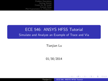
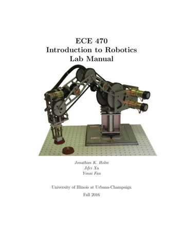
3.4. PROCEDURE13Figure 3.1: Wrist z axes do not intersect.3.4Procedure3.4.1Physical Implementation1. Download and extract lab3.zip from the course website. Inside thispackage are a number of files to help complete the lab, very similar tothe one provided for lab 2.2. Before we proceed, we must define coordinate frames so each of thejoint angles make sense. For the sake of the TA’s sanity when helpingstudents in the lab, DH frames have already been assigned in Figure 3.3(on the last page of this lab assignment). On the figure of the Rhino,clearly label the joint angles {θ1 , θ2 , θ3 , θ4 , θ5 }, being careful that thesense of rotation of each angle is correct.Notice that the z3 and z4 axes do not intersect at the wrist, as shownin Figure 3.1. The offset between z3 and z4 requires the DH frames atthe wrist to be assigned in an unexpected way, as shown in Figure 3.3.Consequently, the zero configuration for the wrist is not what we wouldexpect: when the wrist angle θ4 0 , the wrist will form a right anglewith the arm. Please study Figure 3.3 carefully.3. Use the rulers provided to measure all the link lengths of the Rhino.Try to make all measurements accurate to at least the nearest halfcentimeter. Label these lengths on Figure 3.3.steps4. Now measure the ratio encoderjoint angle for each joint. Use the teach pendant to sweep each joint through a 90 angle and record the startingand ending encoder values for the corresponding motor. Be careful
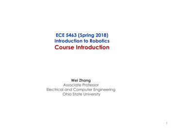
14LAB 3. FORWARD KINEMATICSFigure 3.2: With the Rhino in the hard home position encoder D is zerowhile joint angle θ2 is nonzero.that the sign of each ratio corresponds to the sense of rotation of eachjoint angle.
3.4. PROCEDURE15For example, in order to measure the shoulder ratio, consider followingthese steps: Adjust motor D until the upper arm link is vertical. Record thevalue of encoder D at this position. Adjust motor D until the upper arm link is horizontal. Recordthe value of encoder D at this position. Refer to the figure of the Rhino robot and determine whetherangle θ2 swept 90 or 90 . Compute the ratio ratioD/2 encD (1) encD (0).θ2 (1) θ2 (0)We are almost ready to write an expression for the motor D encoder,but one thing remains to be measured. Recall that all encoders are setto 0 when the Rhino is in the hard home configuration. However, inthe hard home position not all joint angles are zero, as illustrated inFigure 3.2. It is tempting to write encD (θ2 ) ratioD/2 θ2 but it is easyto see that this expression is incorrect. If we were to specify the jointangle θ2 0, the expression would return encD 0. Unfortunately,setting encoder D to zero will put the upper arm in its hard homeposition. Look back at the figure of the Rhino with the DH framesattached. When θ2 0 we want the upper arm to be horizontal. Wemust account for the angular offset at hardhome.
16LAB 3. FORWARD KINEMATICS5. Use the provided protractors to measure the joint angles when theRhino is in the hard home position. We will call these the joint offsetsand identify them as θi0 . Now we are prepared to write an expressionfor the motor D encoder in the following form:encD (θ2 ) ratioD/2 (θ2 θ20 ) ratioD/2 θ2 .Now, if we were to specify θ2 0, encoder D will be set to a valuethat will move the upper arm to the horizontal position, which agreeswith our choice of DH frames.6. Derive expressions for the remaining encoders. You will quickly noticethat this is complicated by the fact that the elbow and wrist motorsare located on the shoulder link. Due to transmission across the shoulder joint, the joint angle at the elbow is affected by the elbow motorand the shoulder motor. Similarly, the joint angle at the wrist is affected by the wrist, elbow, and shoulder motors. Consequently, theexpressions for the elbow and wrist encoders will be functions of morethan one joint angle.It is helpful to notice the trasmission gears mounted on the shoulderand elbow joints. These gears transmit the motion of the elbow andwrist motors to their respective joints. Notice that the diameter of thetransmission gears is the same. This implies that the change in theshoulder joint angle causes a change in the elbow and wrist joint anglesof equal magnitude. Mathematically, this means that θ3 is equal tothe change in the shoulder angle added or subtracted from the elbowangle. That is, θ3 ((θ3 θ30 ) (θ2 θ20 )).A similar expression holds for θ4 . It is up to you to determine the sign in these expressions.3.4.2Theoretical Solution1. Construct a table of DH parameters for the Rhino robot. Use the DHframes already established in Figure 3.3.2. Write a Robotica source file containing the Rhino DH parameters.Consult Appendix A of this lab manual for assistance with Robotica.
3.5. REPORT173. Write a Mathematica file that finds and properly displays the forwardkinematic equation for the Rhino. Consult Appendix A of this labmanual for assistance with Mathematica.4. OR Use matlab ”Denavit Hartenberg Parameters” to calculate theforward kinematics. Use simplify() in matlab as you see fit.3.4.3Comparison1. The TA will supply two sets of joint angles {θ1 , θ2 , θ3 , θ4 , θ5 } for thedemonstration. Record these values for later analysis.2. Run the executable file and move the Rhino to each of these configurations. Measure the x,y,z position vector of the center of the gripperfor each set of angles. Call these vectors r1 and r2 for the first andsecond sets of joint angles, respectively.3. In Mathematica OR Matlab, specify values for the joint variables thatcorrespond to both sets of angles used for the Rhino. Note the vectord05 (θ1 , θ2 , θ3 , θ4 , θ5 ) for each set of angles. Call these vectors d1 and d2 .(Note that Mathematica expects angles to be in radians, but you caneasily convert from radians to degrees by adding the word Degree aftera value in degrees. For example, 90 Degree is equivalent to π2 .)4. For each set of joint angles, Calculate the error between the two forward kinematic solutions. We will consider the error to be the magnitude of the distance between the measured center of the gripper andthe location predicted by the kinematic equation:error1 kr1 d1 k q(r1x d1x )2 (r1y d1y )2 (r1z d1z )2 .A similar expression holds for error2 . Because the forward kinematicscode will be used to complete labs 4 and 6, we want the error to be assmall as possible. Tweak your code until the error is minimized.3.5ReportAssemble the following items in the order shown.1. Coversheet containing your names, “Lab 3”, and the weekday and timeyour lab section meets (for example, “Tuesday, 3pm”).
18LAB 3. FORWARD KINEMATICS2. A figure of the Rhino robot with DH frames assigned, all joint variablesand link lengths shown, and a complete table of DH parameters.3. A clean derivation of the expressions for each encoder. Please sketchfigures where helpful and draw boxes around the final expressions.4. The forward kinematic equation for the tool position only of the Rhinorobot. Robotica and the matlab ”DH parameters” will generate theentire homogenous transformation between the base and tool frames"T50 (θ1 , θ2 , θ3 , θ4 , θ5 ) R50 (θ1 , θ2 , θ3 , θ4 , θ5 )000d05 (θ1 , θ2 , θ3 , θ4 , θ5 )1#but you only need to show the position of the tool frame with respectto the base framed05 (θ1 , θ2 , θ3 , θ4 , θ5 ) [vector expression].5. For each of the two sets of joint variables you tested, provide thefollowing: the set of values, {θ1 , θ2 , θ3 , θ4 , θ5 } the measured position of the tool frame, ri the predicted position of the tool frame, di the (scalar) error between the measured and expected positions,errori .6. A brief paragraph (2-4 sentences) explaining the sources of error andhow one might go about reducing the error.3.6DemoYour TA will require you to run your program twice, each time with adifferent set of joint variables.3.7GradingGrades are out of 3. Each successful demo will be graded pass/fail with apossible score of 1. The remaining point will come from the lab report.
3.7. GRADINGFigure 3.3: Rhino robot with DH frames assigned.19
20LAB 3. FORWARD KINEMATICS
LAB 4Inverse Kinematics4.1ObjectivesThe purpose of this lab is to derive and implement a solution to the inversekinematics problem for the Rhino robot, a five degree of freedom (DOF)arm without a spherical wrist. In this lab we will: derive the elbow-up inverse kinematic equations for the Rhino write a cpp function that moves the Rhino to a point in space specifiedby the user.4.2ReferenceChapter 3 of SH&V provides multiple examples of inverse kinematics solutions.4.34.3.1TasksSolution DerivationGiven a desired point in space (x, y, z) and orientation {θpitch , θroll }, writefive mathematical expressions that yield values for each of the joint variables.For the Rhino robot, there are (in general) four solutions to the inversekinematics problem. We will implement only one of the elbow-up solutions.21
22LAB 4. INVERSE KINEMATICS In the inverse kinematics problems we have examined in class (for 6DOF arms with spherical wrists), usually the first step is to solve forthe coordinates of the wrist center. Next we would solve the inverseposition problem for the first three joint variables.Unfortunately, the Rhino robots in our lab have only 5 DOF and nospherical wrists. Since all possible positions and orientations requirea manipulator with 6 DOF, our robots cannot achieve all possibleorientations in their workspaces. To make matters more complicated,the axes of the Rhino’s wrist do not intersect, as do the axes in thespherical wrist. So we do not have the tidy spherical wrist inversekinematics as we have studied in class. We will solve for the jointvariables in an order that may not be immediately obvious, but is aconsequence of the degrees of freedom and wrist construction of theRhino. We will solve the inverse kinematics problem in the following order:1. θ5 , which is dependent on the desired orientation only2. θ1 , which is dependent on the desired position only3. the wrist center point, which is dependent on the desired positionand orientation and the waist angle θ14. θ2 and θ3 , which are dependent on the wrist center point5. θ4 , which is dependent on the desired orientation and arm anglesθ2 and θ3 . The orientation problem is simplified in the following way: instead ofsupplying an arbitrary rotation matrix defining the desired orientation,the user will specify θpitch and θroll , the desired wrist pitch and rollangles. Angle θpitch will be measured with respect to the zw , the axisnormal to the surface of the table, as shown in Figure 4.1. The pitchangle will obey the following rules:1. 90 θpitch 270 2. θpitch 0 corresponds to the gripper pointed down3. θpitch 180 corresponds to the gripper pointed up4. 0 θpitch 180 corresponds to the gripper pointed away fromthe base5. θpitch 0 and θpitch 180 corresponds to the gripper pointedtoward the base.
4.4. PROCEDURE23Figure 4.1: θpitch is the angle of the gripper measured from the axis normalto the table.4.3.2ImplementationImplement the inverse kinematics solution by writing a cpp function to receive world frame coordinates (xw , yw , zw ), compute the desired joint variables {θ1 , θ2 , θ3 , θ4 , θ5 }, and command the Rhino to move to that configuration using the lab3.cpp function written for the previous lab.4.4Procedure1. Download and extract lab4.zip from the course website. Inside thispackage are a number of files to help complete the lab. You will alsoneed to copy functions implemented in lab3.cpp file which you wrotefor the previous lab to current lab4.cpp.2. Establish the world coordinate frame (frame w) centered at the cornerof the Rhino’s base shown in Figure 4.2. The xw and yw plane shouldcorrespond to the surface of the table, with the xw axis parallel tothe sides of the table and the yw axis parallel to the front and backedges of the table. Axis zw should be normal to the table surface,with up being the positive zw direction and the surface of the tablecorresponding to zw 0.
24LAB 4. INVERSE KINEMATICSFigure 4.2: Correct location and orientation of the world frame.We will solve the inverse kinematics problem in the base frame (frame0), so we will immediately convert the coordinates entered by the userto base frame coordinates. Write three equations relating coordinates(xw , yw , zw ) in the world frame to coordinates (x0 , y0 , z0 ) in the baseframe of the Rhino.x0 (xw , yw , zw ) y0 (xw , yw , zw ) z0 (xw , yw , zw ) Be careful to reference the location of frame 0 as your team defined itin lab 3, as we will be using the functions copied from lab3.cpp fileyou created.3. The wrist roll angle θroll has no bearing on our inverse kinematicssolution, therefore we can immediately write our first equation:θ5 θroll .(4.1)4. Given the desired position of the gripper (x0 , y0 , z0 ) (in the base frame),write an expression for the waist angle of the robot. It will be helpfulto project the arm onto the x0 y0 plane.θ1 (x0 , y0 , z0 ) (4.2)
4.4. PROCEDURE25Figure 4.3: Diagram of the wrist showing the relationship between the wristcenter point (xwrist , ywrist , zwrist ) and the desired tool position (x0 , y0 , z0 )(in the base frame). Notice that the wrist center and the tip of the tool arenot both on the line defined by θpitch .5. Given the desired position of the gripper (x, y, z)0 (in the base frame),desired pitch of the wrist θpitch , and the waist angle θ1 , solve for thecoordinates of the wrist center. Figure 4.3 illustrates the geometry atthe wrist that involves all five of these parameters.xwrist (x0 , y0 , z0 , θpitch , θ1 ) ywrist (x0 , y0 , z0 , θpitch , θ1 ) zwrist (x0 , y0 , z0 , θpitch , θ1 ) Remember to account for the offset between wrist axes z3 and z4 , asshown in Figure 4.3.6. Write expressions for θ2 and θ3 in terms of the wrist center positionθ2 (xwrist , ywrist , zwrist ) (4.3)θ3 (xwrist , ywrist , zwrist ) (4.4)as we have done in class and numerous times in homework.7. Only one joint variable remains to be defined, θ4 . Note: θ4 6 θpitch(see if y
Read "A Gentle Introduction to ROS", available online, Speci cally: Chapter 2: 2.4 Packages, 2.5 The Master, 2.6 Nodes, 2.7.2 Messages and message types. Chapter 3 Writing ROS programs. 2.3 References Consult Appendix B of this lab manual for details of ROS and cpp functions used to control the Rhino. "A Ge