Transcription
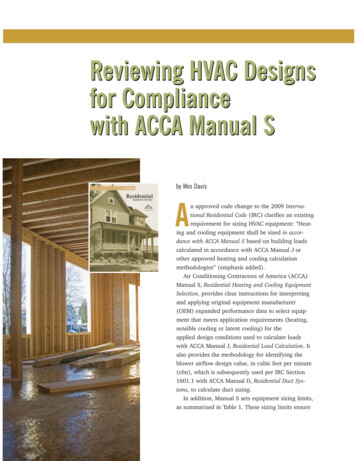
Reviewing HVAC Designsfor Compliancewith ACCA Manual Sby Wes DavisAn approved code change to the 2009 International Residential Code (IRC) clarifies an existingrequirement for sizing HVAC equipment: “Heating and cooling equipment shall be sized in accordance with ACCA Manual S based on building loadscalculated in accordance with ACCA Manual J orother approved heating and cooling calculationmethodologies” (emphasis added).Air Conditioning Contractors of America (ACCA)Manual S, Residential Heating and Cooling EquipmentSelection, provides clear instructions for interpretingand applying original equipment manufacturer(OEM) expanded performance data to select equipment that meets application requirements (heating,sensible cooling or latent cooling) for theapplied design conditions used to calculate loadswith ACCA Manual J, Residential Load Calculation. Italso provides the methodology for identifying theblower airflow design value, in cubic feet per minute(cfm), which is subsequently used per IRC Section1601.1 with ACCA Manual D, Residential Duct Systems, to calculate duct sizing.In addition, Manual S sets equipment sizing limits,as summarized in Table 1. These sizing limits ensureJanuary-February 2009 building safety journal 21
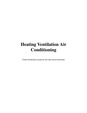
Manual S (continued)Table 1. Manual S equipment selection sizing limitations.EquipmentSizing LimitationsReference(section)Furnaces100–140% of total heating load2-2boilers100–140% of total heating load2-2air conditioners115% of total cooling load*3-4115%1heat pumpsor125%2of total cooling load*4-4supplemental heat(heat pumps)electricbased on equipment balance point4-8dual fuel100–140% of total heating load6-8emergency heat(heat pumps)based on local codes4-91. Heat pumps in a cooling dominant climate are allowed to be 115% of the cooling level.2. Heat pumps in a heating dominant climate are allowed to be 125% of the cooling level.*The size of the cooling equipment must be based on the same temperature and humidity conditions that were used to calculate theManual J loads.that equipment capacities meet the minimum needs of occupants while preventing the problems associated withoversizing.1Heating, Part OneBtu/h and 78,400 Btu/h (140% x 56,000). Per the manufacturer’s product data given in Figure 1, XYZ model FR80-036—with an output capacity of 64,000 Btu/h—meetsthe requirement. Model FR 80-024 does not meet theminimum design temperature, while FR 125-036 hastoo much output capacity.Manual J heating load calculations produce values, inBritish thermal units per hour (BTU/h), for selectingHVAC equipment.Take for example a home that requires a minimum of56,000 Btu/h of heat to maintain an indoor temperatureof 70 F when the outdoor temperature drops in the winter.Based on the sizing limitations (100%–140% of heatingload), the furnace must have a capacity between 56,000The cooling loads given in Manual J for the examplehome are: total cooling 30,000 Btu/h, sensible cooling 22,000 Btu/h and latent cooling 8,000 Btu/h. Basedon the Manual S sizing limitations (100%—115% of thecooling load), the air conditioner must have a capacitybetween 30,000 Btu/h and 34,500 Btu/h (115% x30,000).How to Apply Manual SCoolingTable 2. Manual D input for design air flow.Mode of rature rise requirement2-6coolingair flow associated with the selectedequipment’s capacity3-11Table 3. Example cooling design conditions.OutdoorConditionsIndoor Conditionsdesigntemperaturerelative designhumidity75 F50% Rh22 building safety journal January-February 2009indoor wet-bulbtemperature(at 75 F and 50% Rh)63 F wet-bulbdesigntemperature95 F
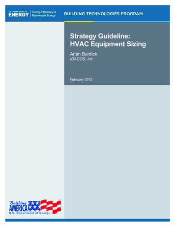
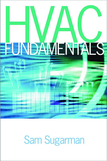
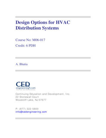
When selecting cooling equipment, it is necessary to know the designconditions used to calculate the cooling load. Unlike heating equipment,cooling equipment OEM data offers a range of performance at different outdoor and indoor conditions. The design conditions for the example home aregiven in Table 3.Figures 2 and 3 provide OEM expanded performance data for two airconditioners: a 2.5-ton capacity model and a 3.0-ton capacity model. Manufacturers may present this data in a different format, but all should includeairflow, entering air wet-bulb temperature,2 outdoor temperature, and cooling capacities (usually, total and sensible capacities). Note that a slightlydifferent approach is employed when using Manual S to verify coolingequipment selection than to select the equipment. Verification begins by considering the outdoor air temperature and indoor wet-bulb temperature.The 2.5-ton air conditioner seems like a natural choice for a home with a30,000 Btu/h cooling load because a 2.5-ton unit has a nominal capacity of30,000 Btu/h. However, the OEM data for XYZ model AC-30 reveals that theunit does not meet the Manual S total cooling capacity requirement at thedesign 95 F outdoor temperature and 63 F entering wet-bulb temperature.In contrast, according to the OEM data, XYZ model AC-36 has enough totalcooling capacity (31,510 Btu/h) without exceeding the 115-percent limit(34,500 Btu/h). The system’s sensible cooling capacity (23,000 Btu/h) alsomeets the sensible cooling load (22,000 Btu/h) and the latent capacity (totalcapacity – sensible capacity latent capacity 8,510 Btu/h) meets the latentload (8,000 Btu/h).Another critical design element is the volume of air that must flow overthe indoor air conditioner coil to achieve the required cooling capacities.3The furnace manufacturer will provide blower performance data indicatingthe air flow that the unit can deliver at different levels of resistance. Referring to the fan performance data given in Figure 4 for XYZ model FR 80-036(1,035 cfm at 0.60 inches water column [iwc], interpolated to 1,050 cfm at0.58 iwc), the furnace can deliver the airflow required per ACCA Manual D.Heating, Part TwoGiven the duct design value of 1,050 cfm, the final hurdle is to determineif the unit selection meets the furnace requirements for temperature rise.Referring back to Figure 1, the XYZ model FR 80-036 furnace has an OEMSensible andLatent LoadsThere are two aspects to theconsideration of cooling load:sensible and latent loads. Thesensible load is the heat that ismeasured by a thermometer ora thermostat. This is the “dry”heat one consciously feels. Thelatent load is the heat associ-ated with airborne moisture asmeasured by a hygrometer orhumidistat.When you enter a homewhose thermostat shows a cooltemperature but which hashigh latent heat—or relativehumidity—the initial feeling iscomfort. But as your body adjusts to the temperature youbegin to feel sticky, clammyand uncomfortable. You mayeven feel warm again. This iswhy two homes with the samethermostat setting can feel verydifferent.XYZ Furnace CompanyFigure 1. Furnace product data for XYZ 3.0-ton air conditioners.January-February 2009 building safety journal 23
Manual S (continued)Model AC-30 with Coil AC-030 (2.5 ton)Figure 2. OEM performance data for XYZ AC-30 2.5-ton air conditioner.Model AC-36 with Coil AC-036 (3.0 ton)Figure 3. OEM performance data for XYZ AC-36 3.0-ton air conditioner.AHRI Versus OEMExpanded Performance DataManufacturers of heating and cooling equipment areresponsible for testing and certifying the performanceof their products. The Air Conditioning, Heating andRefrigeration Institute (AHRI) produces standards forrating such equipment, but data published in AHRIproduct directories should not be used because the testconditions simulate a very small geographic area in theU.S. As such, AHRI directories should only be used tocompare equipment efficiency ratings—OEM expandedperformance data should be used to select properlysized equipment.24 building safety journal January-February 2009design temperature rise range of 35 F–65 F.Air temperature rise through the furnace dependson the rate of flow through the heat exchanger. If theair flow is outside of the temperature rise range, theequipment may cycle off at safety limits, suffer damage or possibly even create an unsafe condition. Incorrect air flow can cause too much temperature rise(slow-moving air may allow the heat exchanger to become too hot, which can result in warping or crackingof the metal heat exchanger) or too little temperaturerise (fast-moving air may cause condensation in themetal heat exchanger, which can result in the production of an acid that can harm or penetrate the heatexchanger).(continued on page 26.)
Manual S (continued)XYZ Company FR 80-036Figure 4. Fan performance data.An air flow rate is acceptable if it yields a temperaturerise within the range prescribed by the equipment manufaturer. In our example, 1,050 cfm equates to an acceptable (35 F–65 F) furnace temperature rise ofapproximately 55 F:ΔT Btu/h4 (CFM 1.1 ACF)55.4 F 64,000 (1,050 1.1 1.0)where:ΔTBtu/hCFMNotes1. Oversizing can lead to health issues associated with excessive humidity; higher costs for equipment and installationlabor and materials; greater energy consumption; and morewear and tear on equipment.2. This considers both the temperature and moisture contentof the air.3. When the blower moves 1,050 cfm over the XYZ model AC36 indoor air conditioner coil, it delivers the required cool- temperature difference in the airbetween the inlet and outlet of thefurnace or cooling coil thermal output capacity of thefurnace or cooling system volume of air, in cubic feet perminute, moved through the furnaceby the blower assembly1.1 a physical air constant (derivedfrom the laws of physics)ACF altitude correction factor; 1.0 at sealevelConclusionThis article serves to demonstrate the value of theadopted code revision in ensuring that appropriate loadcalculations are used as the basis for HVAC equipmentselection: one more way that First Preventers can protectthe health and safety of building occupants across thecountry. 26 building safety journal January-February 2009ing capacity. If the airflow value changes, the equipmentcapacity and performance also change.4. In this case, the actual furnace output capacity of 64,000Btu/h is used, not the 56,000 Btu/h designcapacity from the load calculation.WES DAVIS is Manager of Technical Services for the Air Conditioning Contractors ofAmerica (ACCA), in which capacity he develops HVAC-oriented technical documents, delivers educational presentations and providestechnical support to ACCA members.He is the author of Bob’s House, a stepby-step case study in the proper design of aresidential HVAC system; serves on severalindustry technical committees; and coordinated the development of ACCA’s QualityMaintenance Standard and Quality Installation Verification Protocols.
n approved code change to the 2009 Interna-tional Residential Code(IRC) clarifies an existing requirement for sizing HVAC equipment: “Heat-ing and cooling equipment shall be sized in accor-dance with ACCA Manual Sbased on building loads calculated in accordance with ACCA Manual